 Small batches, high standards. Our rapid prototyping service makes validation faster and easier —

Essential Design Principles for Flawless Drawing Dies

TL;DR
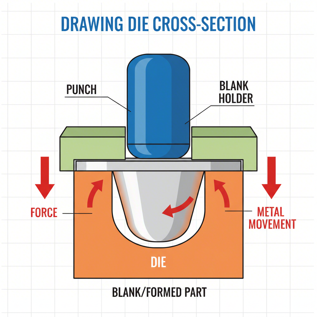
A drawing die is a specialized tool that shapes flat sheet metal into a seamless, three-dimensional hollow part. It operates by using a punch to stretch the metal into a die cavity while a blank holder controls the material's movement. Successful design hinges on precisely managing this metal flow by optimizing critical factors like material properties, draw ratio, lubrication, binder pressure, and die radii to prevent defects such as wrinkling, tearing, or fracturing.
Understanding the Fundamentals of Deep Drawing
The core principle of a drawing die is the controlled deformation of sheet metal. Unlike cutting or bending, the drawing process reshapes a flat metal blank by stretching and compressing it into a hollow form without seams. This method is fundamental for manufacturing a vast range of products, from automotive body panels and kitchen sinks to cookware and industrial components. The process relies on a coordinated set of tools working together under immense pressure to achieve the desired geometry.
The operation begins when a flat sheet of metal, known as the blank, is placed on the die surface. A component called the blank holder, or binder, descends to clamp the edges of the blank. This clamping force is critical for controlling how the material is pulled into the die. Next, the punch, which has the shape of the part's internal cavity, moves downward, pushing the metal into the die cavity. As the punch descends, it forces the metal to stretch and flow over the die's entry radius, transforming the flat sheet into a 3D part. The goal is to achieve this transformation without compromising the material's integrity.
Several key components are essential for this process to work correctly. According to experts at Alsette, these include the punch, the die cavity, and the blank holder. The Punch forms the part's inner shape, the Die Cavity defines its outer geometry, and the Blank Holder applies controlled pressure to the blank's perimeter to regulate metal flow. In more complex designs, Draw Beads—small ridges on the die or binder surface—are used to add friction and further refine the flow in specific areas, preventing defects.
Key Design Factors for Successful Metal Flow
The success of any deep drawing operation is dictated by the ability to control metal flow. If the metal flows too quickly, it can wrinkle; if it is restricted too much, it will stretch thin and tear. Achieving this balance requires a deep understanding of numerous interconnected variables. Each factor must be carefully considered during the die design phase to ensure a stable and repeatable manufacturing process.
A comprehensive list of these factors is crucial for any designer. As detailed in an article by The Fabricator, the primary elements influencing metal flow include:
- Material Properties: The type, thickness, and grade of the metal are foundational. Thicker materials are stiffer and can stretch further, while properties like the work-hardening exponent (N-value) and plastic strain ratio (R-value) determine the material's ability to stretch and draw.
- Blank Size and Shape: An oversized blank can restrict metal flow, while an optimized shape can reduce waste and prevent defects.
- Draw Ratio: This is the relationship between the blank diameter and the punch diameter. If the ratio is too large, the material can stretch too thin and fracture.
- Die Radii: The radius of the die entry point is critical. A radius that is too small can cause tearing, while one that is too large can lead to wrinkling because it reduces control over the material.
- Binder Pressure (Blank Holder Force): Insufficient pressure allows wrinkles to form, while excessive pressure restricts flow and causes tearing. Standoffs, often set at 110% of the material thickness, can be used to maintain a precise gap and allow for material thickening.
- Lubrication: Proper lubrication reduces friction between the die components and the workpiece, preventing scoring and facilitating smooth material flow.
- Press Speed: The speed of the press ram must be slow enough to allow the material sufficient time to flow without fracturing.
The interplay between these factors is complex. For example, the ideal die entry radius depends on the material's thickness and type. For round draws in quality steel, a small radius can cause fracturing, while a large one may lead to wrinkling, especially with thin-gauge stock. Similarly, the required binder pressure changes based on the material; high-strength steels may require up to three times more pressure than low-carbon steel.
Designing Die Components: Punch, Die, and Blank Holder
The physical components of the drawing die—the punch, die, and blank holder—are where design principles are put into practice. The geometry, dimensions, and surface finish of each component directly impact the quality of the final part. Precise calculations and adherence to best practices are essential for creating tooling that is both effective and durable.
The punch and die cavity work together to define the part's final shape. The clearance between these two components is a critical dimension. According to HARSLE Press, this gap is typically set slightly larger than the material thickness to accommodate thickening that occurs during drawing. A gap that is too small increases drawing force and can cause excessive thinning or tearing, while a gap that is too large can result in wrinkles and poor dimensional accuracy. The fillet radius on both the punch (rp) and the die (rd) must also be carefully selected. A small punch radius concentrates stress and can lead to fractures at the bottom of the part.
The blank holder is arguably the most important component for controlling metal flow. Its primary function is to apply a consistent, predetermined pressure on the blank's flange area. This prevents wrinkles from forming as the material is compressed circumferentially while being drawn into the die. The surface of the blank holder must be perfectly parallel to the die surface to ensure even pressure distribution. For complex parts, especially in the automotive industry, draw beads are integrated into the blank holder or die to create additional restraining forces in specific areas, allowing for greater control over the forming process.
Executing these intricate designs requires significant expertise in both engineering and manufacturing. Companies specializing in high-precision tooling, such as Shaoyi (Ningbo) Metal Technology Co., Ltd., leverage advanced CAE simulations and years of experience to produce custom automotive stamping dies for OEMs and Tier 1 suppliers. Their work in creating dies for everything from structural components to complex body panels highlights the importance of mastering these design principles to achieve efficiency and quality in mass production.
Best Practices for Preventing and Troubleshooting Defects
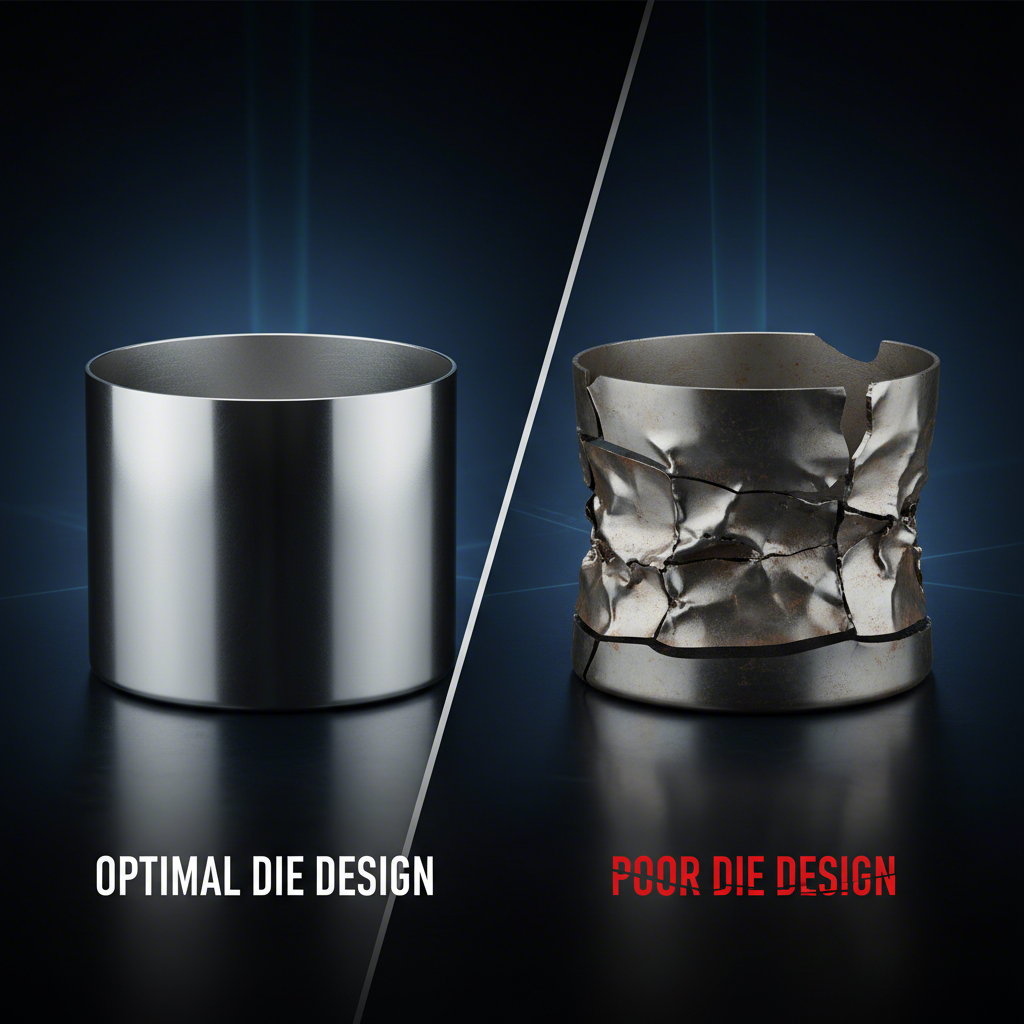
Even with careful design, defects can occur during the deep drawing process. Understanding the root causes of common failures like wrinkling, tearing, and fracturing is key to troubleshooting and prevention. Most defects can be traced back to an imbalance in the forces controlling metal flow. By adhering to established best practices, engineers can minimize scrap rates and improve production stability.
One of the most fundamental best practices, as noted by Dramco Tool, is to avoid sharp corners in the part design. Sharp radii concentrate stress, creating weak points where the material is likely to tear or fracture. Generous, smooth radii on both the part and the die tooling allow the metal to flow more easily and distribute stress over a larger area. Additionally, understanding the part's design intent is crucial. Knowing how a part will be used helps inform decisions about tolerances and critical features, preventing over-engineering and reducing manufacturing complexity.
A systematic approach to troubleshooting can save significant time and resources. The following table outlines common defects, their likely design-related causes, and recommended solutions based on the principles discussed.
| Defect / Symptom | Potential Design Cause | Recommended Design Solution |
|---|---|---|
| Wrinkling in the flange or wall of the part. | Insufficient binder pressure; die entry radius is too large; excessive clearance between punch and die. | Increase blank holder force; reduce the die entry radius to gain more control; decrease the punch-die clearance to within 110% of material thickness. |
| Tearing / Fracturing near the punch radius or at the bottom of the part. | Punch radius is too small; excessive binder pressure restricting metal flow; poor lubrication. | Increase the punch fillet radius (typically to at least 2-3 times material thickness); reduce binder pressure; improve lubrication. |
| Fracturing at the top of the cup wall. | Draw ratio is too large for a single operation; die entry radius is too small. | Introduce an intermediate drawing stage (draw reduction); increase the die entry radius to facilitate easier flow. |
| Surface Scratches or Galling on the part. | Poor die surface finish; inadequate or incorrect lubricant. | Polish the die surfaces, especially the radii, in the direction of metal flow; select a lubricant designed for high-pressure applications. |
Frequently Asked Questions About Drawing Die Design
1. What are the principles of a die?
The fundamental principles of a drawing die revolve around controlling the flow of sheet metal to form a 3D shape without defects. This involves managing factors like material stretchability, applying appropriate binder pressure to prevent wrinkles, using correct radii to avoid tearing, and ensuring proper lubrication to reduce friction. The ultimate goal is to balance the forces of compression and tension on the material throughout the forming process.
2. What is a die design rule?
A key die design rule is to ensure that the tooling geometry facilitates smooth, controlled material flow. This includes setting the punch-to-die clearance at approximately 110% of the material thickness, designing die entry radii to be 4 to 8 times the material thickness, and calculating the draw ratio to be within the material's limits. Another critical rule is to design for the material's properties, accounting for its thickness, strength, and formability.
3. What are the principles of tool and die?
The principles of tool and die design emphasize creating durable, precise, and efficient tooling for manufacturing. This includes proper material selection for the tool itself (often hardened tool steel), calculating correct clearances to achieve part tolerances, and designing components to withstand the high forces of production. The design must also account for tool wear and maintenance to ensure consistent, high-quality part production over the tool's lifespan.
4. What is the basic principle of drawing?
The basic principle of drawing is the transformation of a flat sheet metal blank into a hollow vessel by stretching the material with a punch into a die cavity. The process is defined by the controlled inward flow of material from the blank's flange, which is regulated by pressure from a blank holder. This controlled flow prevents defects and ensures the part is formed to the desired depth and shape without fracturing.