 Small batches, high standards. Our rapid prototyping service makes validation faster and easier —

Die for Manufacturing Types Mapped to Volume, Cost, and Risk
Understanding the Die for Manufacturing Landscape
When you hear the term die for manufacturing, you might picture complex machinery or intricate metal parts. But what exactly is a die, and why is it so central to modern production? Let’s break down the essentials so you can navigate the world of dies, tooling, and high-volume manufacturing with confidence.
What is a Die in Manufacturing?
Simply put, a die is a precision-engineered tool designed to shape, cut, or form material—most often sheet metal or plastic—using force from a press. In the context of what is tool and die, the die represents the part of the system that directly interacts with the raw material to produce repeatable, interchangeable parts. While the broader category of tooling includes fixtures, jigs, and molds, the tool and die definition focuses on components that impart a specific geometry to the workpiece through processes like stamping, forming, or blanking.
Dies are not generic tools; they are custom-built for each application, whether you’re producing automotive body panels, brackets, or electrical contacts. Their job is to ensure every part meets tight tolerances, time after time, across thousands or even millions of cycles.
Core Die Operations and Components
Sounds complex? It can be, but most dies perform a handful of core operations. Here’s how they work:
- Blanking: Cutting flat shapes from sheet material, often the first step in creating a part.
- Piercing: Creating holes or openings by pushing a punch through the material.
- Bending: Deforming material along a straight axis to form channels, flanges, or tabs.
- Drawing: Forming deep or contoured shapes by pulling material into a cavity (think of an automotive door panel).
- Forming: Encompasses a range of operations, including flanging, stretching, and coining, to achieve the final part geometry.
To follow the conversation in later sections, familiarize yourself with these die components:
- Punch: The male part that pushes into the material to cut or form.
- Die button (or die block): The female part that receives the punch and supports the workpiece.
- Stripper: A plate or pad that removes the workpiece from the punch after the operation.
- Pilots: Pins that ensure precise alignment of the material for each cycle.
- Carriers: Features or tabs in progressive dies that keep the part attached to the strip as it moves through each station.
- Shut height: The total closed height of the die set, critical for press setup.
Where Tool and Die Fit in Production
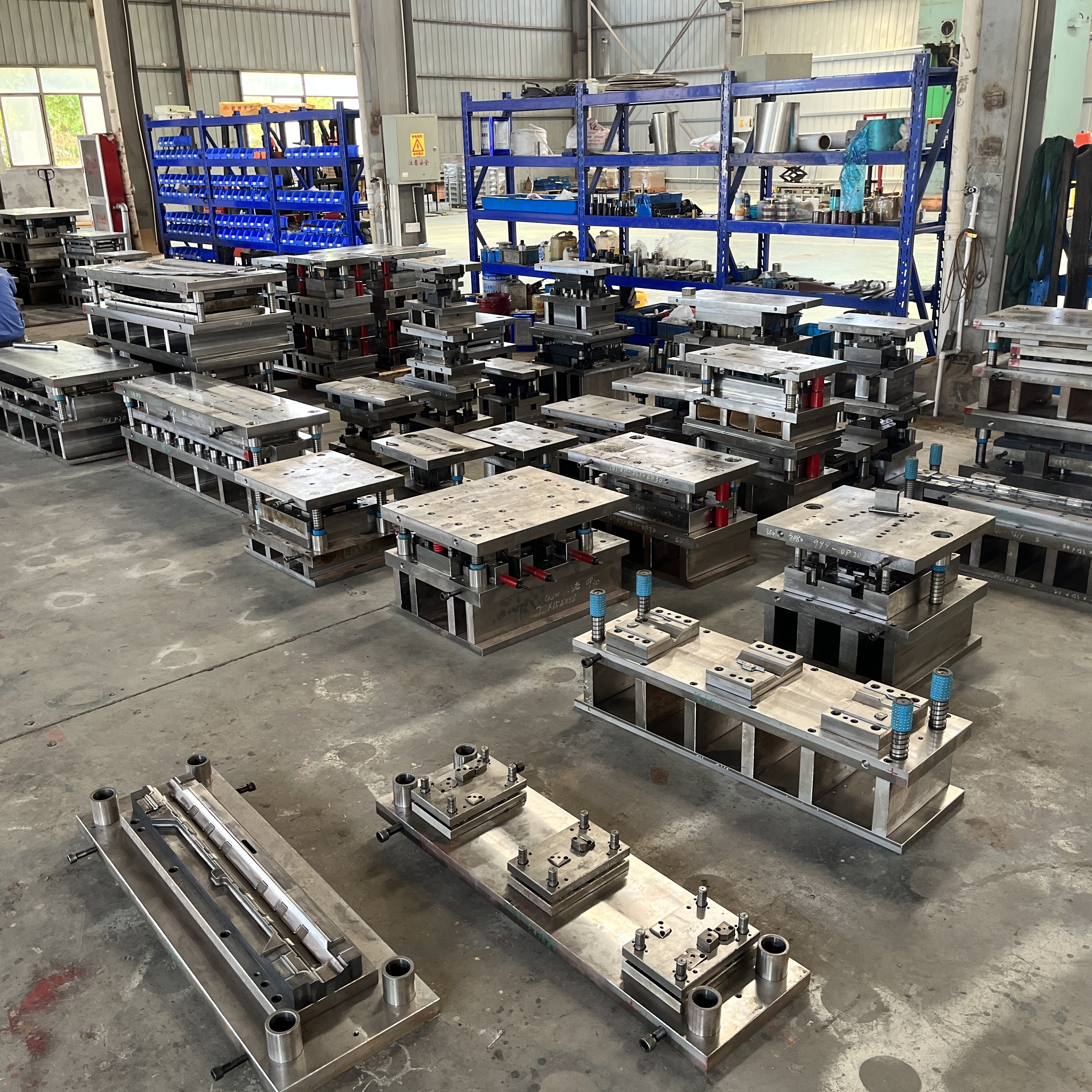
Imagine a busy stamping floor. The press tool (die) sits at the heart of the operation, mounted in a press that delivers the force needed for each cycle. Unlike general-purpose fixtures or assembly jigs, dies are responsible for the direct transformation of raw material into finished or near-finished parts. Their design is tailored for repeatability, interchangeability, and ease of maintenance—key factors in keeping production lines running smoothly and minimizing downtime.
There are several main types of dies you’ll encounter:
- Progressive dies: Perform multiple operations in sequence as the strip advances through the die, ideal for high-volume, complex parts.
- Transfer dies: Move parts from one station to another, often used for larger or more intricate shapes.
- Line dies: Operate as single stations, typically for low-volume or simple parts.
Each approach has its place depending on the part design, production volume, and risk tolerance. You’ll notice that choosing the right die for manufacturing is a strategic decision that shapes your project’s cost, quality, and speed.
Early design-for-manufacture reviews with your tool and die team help catch issues before they reach the press—reducing costly tryout loops and keeping projects on schedule.
In summary, understanding what are dies and their role within the broader tool and die landscape is the first step to making informed decisions about your next manufacturing project. Engage your tooling experts early, and you’ll set the stage for smoother launches and more reliable production outcomes.
Die Types and Real-World Fit
When you’re planning a new manufacturing project, one of the first questions you’ll face is: What type of die best fits your part, volume, and budget? The answer isn’t always obvious, especially when you consider the many types of dies available for dies and stamping operations. Let’s break down the main categories—progressive, transfer, line, compound, and single-hit dies—so you can make a confident, informed choice.
Types of Dies and When to Use Them
Imagine walking onto a shop floor lined with presses—each running a different stamping die. How do you know which die for press is right for your job? Here’s a quick overview of the most common die types used in metal stamping dies and sheet metal die work:
| Die Type | Typical Production Range | Part Complexity | Material Feeding | Setup Time | Maintenance | Formability Risk |
|---|---|---|---|---|---|---|
| Single-Hit / Line Dies | Low (prototyping, service parts) | Simple | Manual or basic automation | Short | Low | Low (few forming steps) |
| Progressive Dies | High (mass production) | Moderate to Complex | Continuous coil feed | Long (initial), short (changeover) | Moderate (regular sharpening/cleaning) | Moderate (multiple forming in sequence) |
| Compound Dies | Medium | Flat, precise parts | Manual or coil feed | Moderate | Low to Moderate | Low (simultaneous simple ops) |
| Transfer Dies | Medium to High | Complex, large, deep-drawn parts | Blank or coil, transferred by automation | Long (setup, tuning transfer system) | High (more moving parts, sensors) | High (multiple free-forming steps) |
Progressive vs Transfer vs Line Dies
Each stamping method brings unique advantages and trade-offs. Let’s compare them in practical terms:
- Single-Hit (Line) Dies: Best for low-volume, simple shapes or jobs where flexibility is key. Quick to set up and change, but slower per part and less automated. Great for prototyping or maintenance/service parts.
- Progressive Dies: The workhorse for high-volume production. Material moves through a series of stations, each adding features or forming steps. High initial investment, but low per-part cost and excellent repeatability. Ideal for small-to-medium complex parts where efficiency and consistency matter most.
- Compound Dies: Combine multiple simple operations—like punching and blanking—at a single station. Efficient for flat, precise parts in medium volumes, but less flexible for complex geometries.
- Transfer Dies: Use automation to move parts from station to station, allowing for large or intricate shapes that can’t stay attached to a strip. Offer flexibility for deep-drawn or complex forming dies but require more setup and maintenance. Best for medium-to-high volumes of challenging parts.
Choosing a Die Type for Your Part
Still not sure which die for manufacturing is right for your project? Here’s a quick guide to help you shortlist options before talking to your engineering team:
- Production Volume: High volumes favor progressive dies; medium volumes may suit compound or transfer dies; low volumes call for single-hit or line dies.
- Part Complexity: Simple, flat parts do well with single-hit or compound dies. Complex, multi-featured parts often require progressive or transfer dies.
- Budget and Cost Structure: Progressive and transfer dies have higher upfront tooling costs but lower per-part costs in volume. Single-hit dies are cheaper to build but costlier per part as volume rises.
- Setup and Maintenance: Consider changeover time, required maintenance frequency, and the skill needed to keep the die running smoothly.
- Material Handling: Coil feeding and automated transfer systems boost throughput but add complexity to the setup.
Pros and Cons of Each Die Type
-
Single-Hit/Line Dies
- Pros: Simple, low cost, flexible for changes, fast setup
- Cons: Slow for high volumes, less automation, higher per-part cost
-
Progressive Dies
- Pros: High efficiency, low per-part cost, ideal for complex sheet metal die work
- Cons: High initial investment, less flexible for design changes, more complex maintenance
-
Compound Dies
- Pros: Good for flat, precise parts, efficient for mid-volumes, moderate cost
- Cons: Limited to simple geometries, not suited for deep or complex forming
-
Transfer Dies
- Pros: Flexible for complex, large, or deep-drawn parts, can combine many forming steps
- Cons: High setup and maintenance requirements, higher operational costs
Before you commit to a tooling concept, weigh these factors against your part’s requirements and your long-term production goals. The right choice of stamping die or forming dies can dramatically impact your project’s cost, quality, and lead time. Next, we’ll explore how these die types are translated into real-world design workflows to minimize rework and maximize production efficiency.
Die Design Workflow That Reduces Rework
Ever wonder how a sheet of metal is transformed into a complex automotive bracket or precision electrical contact—over and over, with no surprises? That journey starts with a robust die design workflow. If you’ve ever faced costly delays or part defects, you know how critical it is to get each step right. Let’s walk through a practical, end-to-end process die workflow that helps you avoid rework, minimize risk, and ensure every manufacturing die delivers as promised.
From Part Print to Strip Layout
It all begins with the part print—the blueprint of your final component. But before any steel is cut, you need to ask: Is this part design feasible for stamping? Here’s where die engineering teams shine. They’ll review:
- Material selection: Is the specified alloy formable? Does thickness or grain direction create risk?
- Geometry: Are there deep draws, tight bends, or sharp corners that could lead to splits or wrinkles?
- Tolerances: Which dimensions are truly critical? Can any be relaxed to simplify the die process?
Once the part is deemed suitable, the strip layout comes next. This is the roadmap for how raw material moves through each die station. A well-planned strip layout minimizes waste and ensures each operation—blanking, piercing, forming, trimming—happens in the right sequence. You’ll notice that this step is often iterative, with several concepts reviewed before locking in the most robust and efficient solution.
Station Planning and Pilot Strategy
With the strip layout defined, it’s time to plan the stations. Each station in the die performs a specific operation. Here’s where you’ll decide:
- Number of stations: How many steps are needed for forming, piercing, bending, and trimming?
- Carrier design: For progressive dies, how will the part remain attached to the strip for accurate transfer?
- Pilots and registration: Where will pins be placed to ensure precise alignment at each station?
- Addendum and binder surfaces: For deep drawing or complex forms, how will the die guide and hold the material to prevent wrinkling or tearing?
- Cams and lifters: Are there features that require side actions or lifting mechanisms? These must be integrated into the die tooling plan early.
- Sensor planning: What sensors are needed to detect misfeeds, double hits, or part ejection issues?
Getting these details right up front is crucial. Imagine skipping pilot placement or underestimating the need for a cam—these oversights can mean expensive rework or even tool failure down the line.
- Part feasibility and material selection
- Formability risk assessment
- Strip layout and station count
- Carrier/transfer design
- Pilots and registration
- Addendum/binder and draw-bead concepts
- Cam and lifter mechanisms
- Sensor plan
- Design freeze and build package
- Tryout and corrective actions
- Final PPAP or equivalent sign-off
Design Freeze, Tryout, and Sign-off
Once every detail is engineered, it’s time to freeze the design. This means no more changes downstream—helping you avoid the domino effect of late-stage rework. The complete build package includes 3D models, 2D die drawing sets, detailed process die instructions, and a parts list for die tooling procurement.
Next comes the tryout phase. Here, the die is built and tested in a press, producing sample parts that are measured and validated. Issues like splits, wrinkles, or dimensional drift are corrected through minor tweaks—never major rework, if the design workflow was followed carefully. Advanced die engineering teams use simulation software (CAE) to predict material flow and spot potential problems before steel is cut, reducing the risk of surprises.
After successful tryout, the die is validated—often using CMM or white light scanning for precise measurement—and the final sign-off (such as PPAP for automotive) is achieved. This means your manufacturing die is ready for production, with quality and repeatability built in from the start.
Freeze upstream decisions before downstream detailing to avoid cascading rework.
By following this step-by-step workflow, you’re not just building a die—you’re building a foundation for reliable, efficient production. Ready to dive deeper? Next, we’ll look at the core calculations and templates that drive successful die design and quality assurance.
Text-Based Templates for Die Engineering Calculations
Ever found yourself staring at a print, wondering how to dial in the right die clearance or compensate for springback on that tricky bend? With so many variables in die for manufacturing, it’s easy to get lost in the numbers. But with the right calculation frameworks, you can adapt proven methods to your specs—no guesswork, just reliable results for every die form and forming dies and tools project.
Blanking and Piercing Clearance Template
Let’s start with blanking and piercing—core operations in any sheet metal dies setup. The punch-to-die clearance directly impacts edge quality, tool life, and downstream processing. Too little clearance? You’ll see excessive wear and rough, uneven edges. Too much? Expect burrs and slug pulling. The trick is to balance material type, thickness, and the desired edge quality.
Clearance = f(Material Type, Thickness, Edge Quality Target). Define f using your internal standard or supplier data. For example, industry guidelines suggest starting with 5% of stock thickness per side, but engineered clearances may range up to 28% per side depending on material properties and performance goals.
- Material grade (steel, stainless, aluminum, etc.)
- Material thickness
- Grain direction
- Edge quality target (burr height, burnish length)
- Coating plans (plating, painting)
- Finishing steps (deburring, secondary forming)
Check your material supplier’s data sheets for recommended clearances, or request a clearance test for critical applications. Review slug appearance after tryout—consistent burnished land and even fracture planes signal correct clearance. If you’re using advanced die processing for high-strength or coated materials, engineered clearances can significantly extend tool life and improve part quality.
Bend Allowance and Setback Framework
When you design a die formed part, getting the blank size right is crucial. Bend allowance (BA) and bend deduction (BD) help you account for stretching and compression during bending. Here’s how to approach it:
Bend Allowance (BA) = (θ/360) × 2π × (R + K × t)
Where:
- θ = bend angle (degrees)<br> - R = inner bend radius
- t = material thickness
- K = Neutral Layer Coefficient (K-Factor), which is a dimensionless constant typically between 0.33 and 0.5, depending on the material, thickness, and bending process
For most sheet metal dies, the K-factor is determined by material and process—consult your in-house standards or use empirical data from previous jobs. Adjust your blank size based on bend allowance or deduction, and always validate with a first-article tryout.
Springback Compensation Strategy
Springback can turn a perfect bend into a headache—especially with high-strength materials or tight radii. Predicting and compensating for springback keeps your forming dies and tools on target. Here’s a practical template:
Springback Angle (Δθ) = (K × σy × R) / (E × t)
Where:
- K = Springback coefficient (0.1–0.2, based on material and bend method)
- σy = Yield strength of material
- R = Bend radius
- E = Elastic modulus of material
- t = Material thickness
- Yield strength (from material data sheet)
- Elastic modulus
- Bend radius and angle
- Material thickness
- Springback coefficient (from experience or test data)
For complex die form geometries or high-value parts, CAE simulation is a game-changer. Simulate the forming process to predict springback, validate your calculations, and fine-tune compensation before cutting steel. This approach is especially valuable when working with advanced alloys or intricate die formed features [engineering.com].
By using these templates and plugging in your real-world data, you’ll bridge the gap between design intent and shop floor reality. Next, we’ll explore how material and coating choices further influence the durability and serviceability of your die for manufacturing.
Materials, Coatings, and Serviceability Choices
Choosing Tool Materials for Cutting and Forming
When you select a die for manufacturing, the choice of die material can make or break your project’s success. Ever wondered why some dies last for millions of hits while others wear out quickly? The answer lies in matching the right steel die or insert to the specific wear, impact, and heat conditions of your process.
For cutting operations like blanking and piercing, you’ll often see cold work die steels such as D2 or A2. These grades offer high hardness and wear resistance, making them ideal for repetitive shearing. D2, for example, is prized for its exceptional wear resistance, while A2 provides a balance of toughness and dimensional stability—helpful if your part geometry is sensitive to temperature swings or shock loading.
Forming dies, on the other hand, are subject to different stresses—think galling, adhesive wear, and high contact pressures. Here, tool steels like H13 (for hot work) or S7 (for impact resistance) shine. H13 is engineered to retain its hardness at elevated temperatures, making it a go-to choice for hot forming or die-casting. For cold forming, powder metallurgy (PM) tool steels are gaining traction, especially with advanced high-strength sheet metals. These PM steels provide a unique blend of toughness and fine carbide distribution, which significantly boosts tool life in challenging applications.
- Steel die for cutting: D2 (wear resistance), A2 (toughness), PM grades (high wear + toughness)
- Steel die for forming: H13 (hot work), S7 (shock resistance), PM tool steels (balanced properties)
- Cast iron/cast steel: Sometimes used for large die sets or base plates, but not for severe wear zones
When to Use Coatings and Surface Treatments
Even the best die steel can wear out fast if the surface isn’t protected. That’s where coatings and treatments come in. Have you ever noticed galling or rapid edge wear on a press plate or punch? Applying the right coating can dramatically extend tool life and reduce downtime.
- PVD (Physical Vapor Deposition) coatings: Titanium nitride (TiN), titanium carbonitride (TiCN), titanium aluminum nitride (TiAlN), and chromium nitride (CrN) are common. They offer high hardness, reduced friction, and excellent resistance to galling—particularly valuable in high-volume stamping or when forming advanced steels.
- Nitriding: Gas or plasma ion nitriding creates a hard, wear-resistant surface layer on the die, ideal for fighting abrasive and adhesive wear. It’s especially effective for die inserts in high-wear locations.
- Chrome plating: Once common, but now less favored due to microcracking and environmental concerns. Not recommended for severe applications with advanced high-strength steels.
Pros and Cons of Coatings and Treatments
-
PVD Coatings
- Pros: Excellent wear/galling resistance, low friction, can be tailored to specific materials
- Cons: Adds upfront cost, substrate must be properly hardened, may require re-coating after tool adjustments
-
Nitriding
- Pros: Hard surface layer, low distortion, enhances base tool steel performance
- Cons: Limited to certain steel grades, not suitable for all geometries
Designing for Serviceability with Inserts
Ever had to stop a line because a small section of the die failed? Modular design with replaceable inserts or hardened die sections is your answer. Strategic use of inserts in high-wear areas lets you swap out just the damaged section, not the entire die set—cutting both downtime and cost. Some advanced tooling dies even use ceramic inserts for extreme wear zones, though these are less common due to brittleness and machining challenges [AHSS Insights].
- Pros: Faster repair, lower lifecycle cost, flexibility for upgrades or material changes
- Cons: Slightly higher initial design complexity, may require precise fitment and alignment
Align your die material and coating choices with the dominant wear and failure mechanisms—whether it’s abrasive wear, galling, or impact—to maximize tool life and minimize unplanned downtime.
Finally, don’t overlook heat treatment. Proper hardening and tempering are vital for achieving the right balance of hardness, toughness, and dimensional stability. Always check die steel supplier datasheets or internal standards to fine-tune your process for each job.
By making smart choices in die material, coatings, and modular design, you’ll build tooling dies and die sets that stand up to the rigors of modern manufacturing. Next, we’ll explore how these material decisions translate into the actual manufacturing process flow, from machining to quality gates.

Die Manufacturing Process Flow and Quality Gates
When you picture a finished die for manufacturing, it’s easy to forget the careful choreography that brings it to life. How does a concept on a screen become a robust, production-ready tool capable of millions of cycles? Let’s walk through the practical steps of die manufacturing, spotlighting the checkpoints and quality gates that ensure your tool performs as designed—every time.
From CNC Roughing to Finish Grind
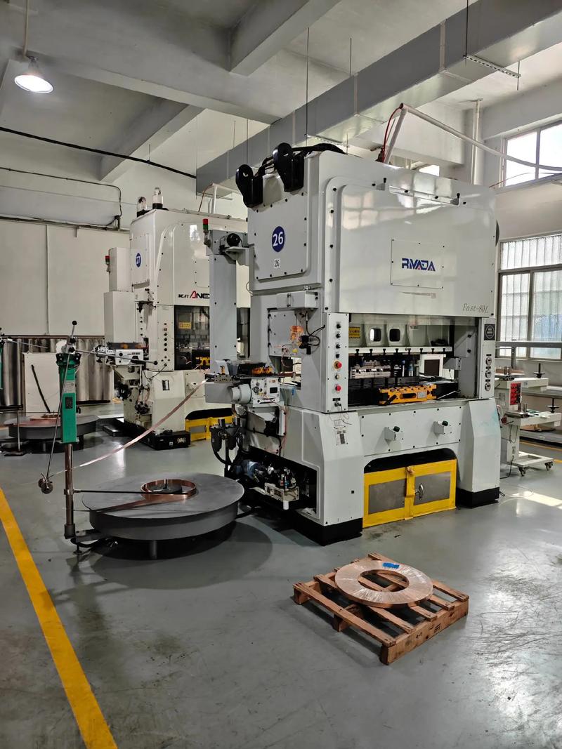
It all starts with a digital blueprint. Once your die design is frozen, the journey from concept to reality follows a disciplined process. Imagine each phase as a relay—passing the baton from one expert to the next, with quality checks at every handoff. Here’s a typical flow you’ll see in tool and die manufacturing:
- CAD/CAM Preparation: Engineers convert the approved die design into precise machining instructions, including datum strategies to control cumulative tolerances. This digital prep ensures every feature aligns with the master reference points for the machine die.
- CNC Roughing: High-speed CNC machines remove the bulk of the material, shaping blocks of die steel into rough forms. Strategic fixturing and datum selection here set the stage for accurate downstream work.
- EDM/Wire EDM: For tight corners, intricate features, or hard-to-reach pockets, Electrical Discharge Machining (EDM) or wire EDM takes over. Careful electrode planning is essential—each electrode must match the intended geometry, and keeping a close eye on electrode wear is key for precision in die machining.
- Heat Treat: Components are heat-treated to achieve the desired hardness and toughness. This step is critical—improper heat treat can cause distortion, so fixtures and support strategies are used to maintain flatness and alignment.
- Finish Grind: After heat treat, grinding brings critical surfaces to their final dimensions and finishes. Here, cumulative tolerances are checked to ensure that all mating die sections will align perfectly in assembly.
- Fitting/Spotting: Skilled toolmakers hand-fit and "spot" mating surfaces, using bluing compounds and manual scraping to achieve full, even contact. This tactile process is where the art of tool die making truly shines.
- Assembly: All die components—blocks, punches, strippers, guides, and sensors—are assembled into the die set. Careful attention to fastener torque and alignment ensures reliable operation on the press.
- Sensor Install: Modern dies often include sensors for part detection, misfeed, or overload. These are installed and tested before live tryout.
- Tryout: The die is run in a press, producing test parts. This phase is a reality check—verifying that all features form correctly, tolerances are held, and the die cycles smoothly. Any issues are addressed through minor adjustments or corrective actions.
- Corrective Actions: If the die shows signs of binding, misalignment, or part defects, toolmakers tweak surfaces, shims, or clearances. Each change is documented for traceability and future reference.
- Documentation Release: Once the die passes all quality gates, final documentation—including as-built drawings, inspection data, and maintenance guides—is released to the production and maintenance teams.
Advance only when mating surfaces meet contact targets and motion is verified through full stroke.
EDM and Heat-Treat Considerations
Ever wondered why some dies last longer or produce more consistent parts? It often comes down to the details in die machining and finishing. EDM allows toolmakers to create sharp corners and complex contours that traditional machining can’t reach. But electrode planning is crucial—using the right material, size, and wear compensation ensures dimensional accuracy for every machining dies project.
Heat treatment, meanwhile, is a balancing act. Too hard, and the die may crack; too soft, and it will wear prematurely. Toolmakers use controlled heating and cooling cycles, often with fixturing, to achieve the perfect blend of hardness and toughness. Each step is validated against material specs and checked for distortion, so the die fits seamlessly into the next phase.
Assembly, Spotting, and Tryout Flow
Once all components are finished, assembly is more than just bolting parts together. It’s about ensuring every interface—guides, bushings, punches—lines up within microns. Spotting is the hands-on process where toolmakers use bluing and manual adjustments to guarantee full contact between die sections. This minimizes uneven wear and ensures consistent part quality.
During tryout, the die is tested under real production conditions. The team checks for smooth operation, verifies all sensors, and inspects sample parts for dimensional accuracy. Any deviations are corrected, and the lessons learned are fed back into internal standards—driving continuous improvement for future tool and die manufacturing projects.
Throughout the process, quality gates are your insurance policy. They catch issues early—before the die ever sees a production line. By documenting each checkpoint and capturing best practices, your team builds a knowledge base that strengthens every new what is die making or tool die making effort.
With your die now production-ready, the next step is to ensure ongoing quality and performance—through robust inspection plans and tolerancing strategies that prevent surprises on the shop floor.
Quality, Tolerancing, and Inspection That Prevent Surprises in Die for Manufacturing
Ever had a die that looked perfect on paper but produced out-of-spec parts on the press? Or maybe you’ve watched a project stall because no one could agree on what “good enough” really meant. When it comes to tools and dies, a rigorous quality and inspection plan is your best insurance policy. Let’s break down how you can set clear expectations, avoid costly surprises, and keep your production running smoothly.
Defining Critical Dimensions and Finishes
Imagine you’re reviewing a new die section for a high-volume stamping line. Where do you start? The answer is with critical dimensions—the features that determine whether your part will fit, function, and last in its final assembly. According to industry best practices, these dimensions should be identified during the design phase and clearly marked on both the die and part drawings. Typical critical features include hole patterns for fasteners, trim edges that must mate with other components, and functional surfaces that affect sealing or movement.
Surface finish expectations are equally important. For working faces of the top die and mating components, specify finish requirements that match the part’s cosmetic or functional needs. A rough finish on a forming surface, for example, can lead to material tearing or inconsistent forming, while overly smooth surfaces may increase the risk of galling. Use your internal standards to set finish targets, and always document them on the build package.
Inspection Plan Across the Tool Lifecycle
Sounds like a lot to track? That’s where a structured inspection plan comes in handy. By defining checkpoints throughout the die’s lifecycle, you can catch issues early and ensure every die for manufacturing delivers reliable results. Here’s a practical inspection flow you can adapt for your own projects:
- Incoming Stock Verification: Confirm material type, grade, and certification before machining begins.
- Component CMM (Coordinate Measuring Machine): Use CMMs to measure machined parts, ensuring all critical and reference dimensions are within your spec.
- Assembly Verification: Check fit and alignment of assembled die sections. Use bluing or spotting compound to verify full contact between mating surfaces.
- Sensor Verification: Test all installed sensors for correct operation—especially in complex or automated dies.
- Dry-Cycle Motion: Cycle the assembled die through its full stroke without material to ensure smooth, interference-free movement.
- First-Piece Inspection: Run sample parts in the press and measure all critical features—using CMMs, calipers, or dedicated gauges as appropriate.
- In-Process Monitoring: Implement periodic checks during production to catch drift, wear, or unexpected die offset.
- End-of-Run Evaluation: Inspect parts and die condition after each production run to identify wear patterns or emerging issues.
By following this sequence, you’ll build confidence that every die section and feature is under control—from raw stock to finished part.
Link every measurement point to a functional outcome: fit, form, and durability. This keeps inspection meaningful and focused on what matters most to your end product.
Qualitative Acceptance Criteria That Stick
Not every feature needs a tight numeric tolerance. For many tools and dies, qualitative criteria—such as "no visible burrs," "full contact over 80% of surface," or "no binding through full stroke"—are just as important. Use these criteria to supplement your quantitative checks, especially for areas like die spotting, surface finish, and part ejection.
Here’s a text-based acceptance checklist you can tailor to your own needs:
| Checkpoint | What to Verify | Acceptance Criteria |
|---|---|---|
| Critical Dimensions | Hole patterns, trim edges, locating features | Within specified tolerances; fits with mating parts |
| Surface Finish | Forming faces, cutting edges, guide surfaces | Meets documented finish requirements; no excessive roughness or galling |
| Assembly Fit | Die section alignment, guide pin fit, shut height | Smooth assembly; no gaps or misalignment; correct shut height |
| Motion | Press cycling, cam/lifter actuation | No binding; full stroke achieved; sensors trigger correctly |
| First-Piece Part | All functional features and cosmetic surfaces | Meets print/spec; no visible defects; passes fit test |
| End-of-Run | Die wear, part consistency | No excessive wear; parts remain in tolerance |
Invite your team to add their own spec values and any special requirements unique to your application. This approach makes the checklist a living document—one that evolves as your shop gains experience and faces new challenges in die for manufacturing.
Finally, remember that measurement technology is advancing fast. From CMMs for component inspection to optical metrology for complex forms, the right tools help you catch issues early and prove your process capability. By anchoring your QA strategy in both quantitative and qualitative checks, you’ll deliver dies that perform reliably—cycle after cycle. Up next, we’ll dive into troubleshooting and maintenance playbooks to keep those high standards intact on the shop floor.

Troubleshooting and Maintenance Playbook
Ever watched production grind to a halt because of a mysterious burr, a split, or a mis-pierced hole? When you rely on a die press or a whole set of tool dies, every minute of downtime can mean missed deadlines and mounting costs. So, how do you quickly diagnose issues and keep your dies running smoothly? Let’s break down proven troubleshooting tactics and best-practice maintenance routines you can apply right away.
Rapid Diagnostics on the Press
When defects pop up—whether it’s a burr, a wrinkle, or a dimensional drift—don’t just “firefight” the symptom. Instead, use a systematic approach to trace the problem back to its root cause. Imagine you’re seeing a part with edge rollover. Is it the punch die clearance, material thickness, or maybe die alignment? The table below maps common symptoms to likely causes and corrective actions, making it easy to take targeted steps instead of trial-and-error fixes.
| Symptom | Probable Cause | Corrective Action |
|---|---|---|
| Burrs on cut edges | Excessive die clearance, dull punch die, misalignment | Adjust clearance, sharpen punch, check die set alignment |
| Edge rollover | Incorrect die clearance, worn punch or die button | Regrind punch/die, reset clearance, replace worn parts |
| Splits or cracks | Material too hard/thick, sharp corners, excessive forming | Review material spec, increase radii, adjust forming sequence |
| Wrinkles | Insufficient blank-holder force, poor strip support | Increase restraining force, check die set flatness |
| Springback | High-strength material, tight bend radius | Adjust overbend, use forming simulation, tweak process parameters |
| Mis-pierce (off-location holes) | Poor pilot alignment, worn guide bushings | Check/replace pilots, inspect bushings, realign die set |
| Dimensional drift | Die wear, temperature fluctuations, loose fasteners | Inspect wear surfaces, retighten fasteners, monitor press temperature |
Corrective Actions That Stick
Sounds simple? The real trick is to fix the underlying cause, not just the symptom. For example, if you see inconsistent wear on your die sets, it could be due to misalignment in the press or uneven die clearance. Regular checks using alignment mandrels and timely replacement of guide bushings can prevent bigger failures down the line. Don’t forget to check the flatness of the plate before each run—a warped blank can lead to forming issues that no amount of punch sharpening will solve.
For more complex issues—like recurring splits or persistent springback—consider using forming simulation software or root-cause analysis techniques (like the "5 Whys" or fishbone diagrams) to systematically uncover deeper process problems. This approach, as noted in industry best practices, moves your team from reactive “firefighting” to proactive prevention [reference].
Maintenance Intervals and Decision Rules
Wondering how often to sharpen a punch die or replace a pin punch set? The answer depends on your production volume, part complexity, and material. But one thing is clear: preventive maintenance always beats emergency repairs. Here’s a quick checklist you can adapt for your shop:
- Sharpen punches and dies after a set shot count or when burr height exceeds your spec
- Replace inserts or wear plates at the first sign of scoring or galling
- Lubricate guide posts, bushings, and sliding surfaces at each shift or per OEM guidance
- Check die set alignment during every major setup or after a crash event
- Inspect fasteners and retorque as needed to prevent die movement
For critical dies, predictive maintenance using sensors (force, vibration, or temperature) is gaining traction. These systems can alert you to wear trends or misalignment before a failure disrupts production.
Still not sure when to refurbish versus replace? If a die set requires frequent emergency repairs, produces inconsistent parts, or shows cumulative damage that can’t be corrected with normal maintenance, it’s time to consider a rebuild or a new tool. Document every intervention—this history helps you spot patterns and make smarter investment decisions for future die for manufacturing projects.
By following these troubleshooting and maintenance playbooks, you’ll minimize downtime, control costs, and keep your die press and tool die sets running like new. Next, we’ll help you translate these requirements into a smart supplier engagement plan for your next automotive or high-volume die project.
Selecting a Die Partner with Automotive Credibility
When you’re sourcing a new die for manufacturing—especially for automotive or high-volume applications—the stakes are high. Imagine investing in a tool only to face missed deadlines, quality issues, or unexpected costs down the road. How do you choose a die maker who not only delivers on specs, but also becomes a strategic partner for the long haul? Let’s walk through a proven approach, backed by industry best practices and a checklist you can use on your next RFQ.
What to Ask Your Die Maker
Sounds complex? It’s easier when you break it down. Before reaching out to die manufacturing companies, clarify your project’s core requirements. This sets the stage for an efficient, focused supplier evaluation—saving you time and reducing costly missteps. Here’s a practical procurement checklist tailored for auto die and automotive die projects:
- Part models and prints – Provide 3D CAD and 2D drawings with tolerances and critical features.
- Annual volume and ramp plan – Estimate yearly quantities and any expected changes over time.
- Material and thickness range – Specify grades, coatings, and sheet thicknesses.
- Cosmetic and dimensional priorities – Highlight critical surfaces, edge conditions, and visible areas.
- Die type preference – Indicate if you need progressive, transfer, or line dies based on part geometry and volume.
- In-press specs – Share press tonnage, shut height, and automation requirements.
- Inspection plan – Define measurement points, CMM needs, and documentation expectations.
- Maintenance expectations – Outline service intervals, spare parts, and support plans.
- Spare parts – List consumables and critical wear items to include in the quote.
- Timeline and deliverables – Set milestones for design reviews, tryout reports, and final documentation.
By sharing this info up front, you help die manufacturers tailor their proposals, avoid costly assumptions, and streamline the entire process. According to industry guidance, defining your requirements early is the first step to aligning with the right tool & die maker for your project’s needs.
Quality, Certification, and Simulation Expectations
Ever wondered what separates a good supplier from a great one? Beyond competitive pricing, look for evidence of robust quality systems and engineering support. For automotive and regulated industries, certifications like IATF 16949 or ISO 9001 are essential—they signal that the supplier’s processes meet global standards for consistency and traceability.
But don’t stop at certificates. Ask your die maker how they use simulation and digital validation. Advanced suppliers leverage CAE (computer-aided engineering) to optimize die geometry, predict material flow, and reduce tryout cycles. This “design for manufacturability” approach helps catch issues before steel is cut, reducing both cost and lead time. If you’re seeking a partner with proven simulation and collaboration capabilities, consider resources like Shaoyi Metal Technology’s Automotive Stamping Dies. Their team combines IATF 16949 certification, CAE-driven feasibility, and in-depth design reviews to deliver dies trusted by leading automotive brands—helping you minimize risk and accelerate launch schedules.
From Quote to Tryout and Handover
Once you’ve shortlisted a tool & die maker, focus on their onboarding and communication process. Will you have clear touchpoints for design reviews, simulation analysis, and tryout feedback? Are timelines realistic, and do they provide transparency on progress and issues? Effective collaboration is a hallmark of successful industrial tool die and engineering partnerships.
During tryout, expect your supplier to validate the die on-press, provide measurement reports, and document any adjustments. The handover package should include as-built drawings, inspection data, and a maintenance plan—ensuring your team can support the tool throughout its lifecycle.
Key takeaway: The best die manufacturers act as partners, not vendors—offering technical guidance, robust QA, and transparent communication from quote through production.
By following this checklist-driven approach and prioritizing quality, certification, and collaboration, you’ll set your project up for long-term success. Whether you’re launching a new automotive platform or scaling up production, the right die partner enables you to deliver reliable, cost-effective results—cycle after cycle.
Frequently Asked Questions About Die for Manufacturing
1. What is a die used for in machining and manufacturing?
A die is a specialized tool used to shape, cut, or form materials—most commonly sheet metal or plastic—by applying force in a press. Dies enable precise, repeatable production of parts such as brackets, panels, and electrical contacts, making them essential for high-volume manufacturing.
2. What are the main types of dies in manufacturing?
The primary types of dies include single-hit (line) dies, progressive dies, compound dies, and transfer dies. Each type is suited for specific applications based on part complexity, production volume, and automation needs. Progressive dies excel in high-volume, complex parts, while single-hit dies are ideal for prototyping or low-volume runs.
3. Why are tool and die reviews important early in the manufacturing process?
Early engagement with tool and die experts helps identify potential design or material issues before production begins. This reduces costly rework, shortens tryout cycles, and ensures the die is optimized for manufacturability, quality, and longevity.
4. How do coatings and material choices affect die performance?
Selecting the right die steel and surface treatments is critical for tool life and part quality. Coatings like PVD or nitriding enhance wear resistance and reduce friction, while material choices such as D2 or H13 tool steels are tailored to specific cutting or forming stresses encountered in manufacturing.
5. What should buyers look for when selecting a die manufacturer for automotive projects?
Buyers should prioritize suppliers with robust quality certifications (like IATF 16949), proven CAE simulation capabilities, and collaborative engineering support. For automotive dies, consider companies that offer comprehensive design reviews, tryout validation, and a track record of supporting high-volume, precision applications, such as those detailed by Shaoyi Metal Technology.