 Small batches, high standards. Our rapid prototyping service makes validation faster and easier —

Essential Strategies for Die Design for Tight Tolerances

TL;DR
Designing dies for tight tolerances requires a strategic shift from simply meeting print specifications to aggressively minimizing process variation. Success hinges on a holistic approach that combines robust tool design—such as using sturdy die shoes and nitrogen springs—with careful material selection and precise process control. By focusing on consistency at every stage, manufacturers can achieve superior part quality and reliability.
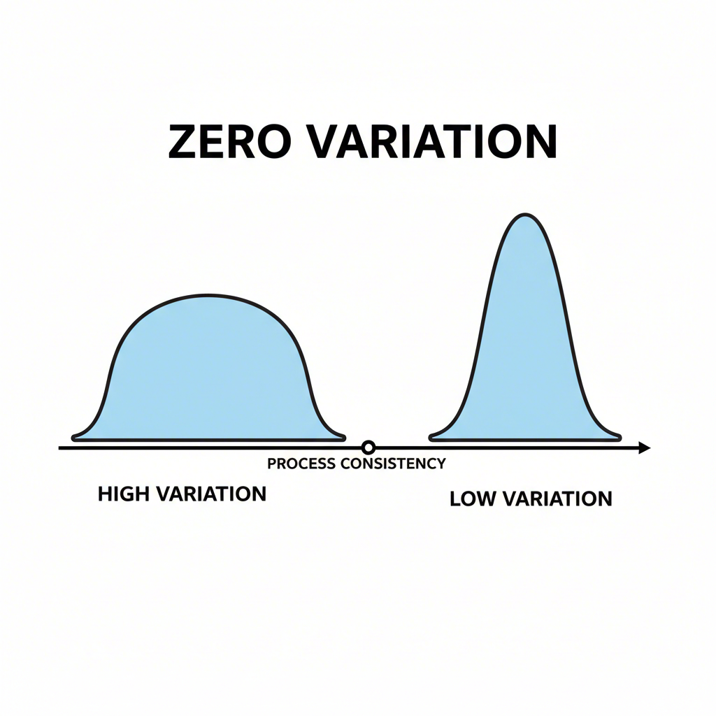
Core Principles: Shifting Focus to Zero Variation
In precision manufacturing, the traditional goal has been to produce parts that are "to-print"—meaning their dimensions fall within a specified tolerance range. However, a more advanced approach, especially for die design, is to focus on achieving near-zero variation. This philosophy prioritizes process consistency over simply staying within the upper and lower limits of a specification. A process with low variation is predictable and controllable, making it easier to adjust and maintain over the long term, even if its average output is slightly off-center from the nominal dimension.
Tight tolerances are often defined by incredibly fine dimensional limits, frequently within ±0.001 inches or even less. When multiple components with high-variation—but still technically in-spec—dimensions are assembled, their individual deviations can accumulate, an issue known as tolerance stack-up. This can lead to assembly problems, functional failures, and costly quality issues down the line. In contrast, a low-variation process produces parts that are nearly identical to one another, ensuring a perfect fit and consistent performance in complex assemblies.
Adopting a zero-variation mindset requires a proactive approach to design. Engineers should conduct a Failure Mode and Effects Analysis (FMEA) early in the die design phase to identify all potential sources of variation. This allows for the implementation of design features and process controls that mitigate these risks from the outset. The long-term benefits, including reduced scrap, lower maintenance costs, and higher product reliability, far outweigh the initial investment in more robust tooling and process development.
Material Selection and Properties for Precision
The material being formed is a primary variable in any stamping operation, and its properties have a direct impact on the ability to hold tight tolerances. Achieving precision begins with a deep understanding of the material's behavior under pressure. Key properties such as density, thickness, hardness, ductility, and elasticity must be carefully considered during the die design phase, as each influences the final dimensions of the stamped part.
Material density, for example, affects the cutting force required and the potential for deflection during the operation. Less dense materials like foams are prone to compression, while denser metals require more force to cut cleanly. According to insights from JBC-Tech, material thickness is another critical factor; thicker materials are inherently more difficult to manage and are more susceptible to defects that compromise tolerances. Furthermore, the material's springback—its tendency to return to its original shape after forming—must be anticipated and compensated for in the die design to ensure accurate final angles and dimensions.
To systematically address these challenges, designers must select materials with purpose. Instead of defaulting to standard thicknesses, specify the exact thickness required for functional performance. For challenging materials, innovative strategies can be employed. As suggested by industry experts, working closely with material suppliers to source high-quality, consistent stock is a crucial first step. The following table outlines common material challenges and corresponding design strategies:
| Material Challenge | Corresponding Design Strategy |
|---|---|
| Elastic Materials (Risk of snap-back/deformation) | Add a stable carrier to improve dimensional stability. |
| Rigid Materials (Risk of fracture or cracking) | Laminate a thin rigid layer to a more compliant backing material. |
| Low-Density Materials (Prone to compression) |
Advanced Tooling and Die Component Design
The physical construction of the die set is the foundation of any high-precision stamping operation. To achieve tight tolerances, the die must be designed for maximum robustness and stability to resist the immense forces exerted during production. This involves using high-quality components and incorporating design features that minimize deflection, ensure precise alignment, and maintain consistency over millions of cycles. Key components include die plates, punches, stripper plates, and guide pins, all of which must work in perfect harmony.
According to an article from MetalForming Magazine, building in robustness is a core principle. This translates to practical design choices such as using thick, sturdy die shoes (the base plates of the die set), implementing robust piloting to accurately locate the material strip, and utilizing nitrogen springs for strong, consistent clamping force. These elements work together to create a stable environment that reduces process variability. For applications requiring extreme precision, specialized techniques like coining can be integrated into the die. Coining involves applying immense pressure to a specific area of the part, causing the metal to flow into the die cavity and achieve highly accurate features.
A compelling example of this is detailed in a case study by Ultra Tool & Manufacturing, where a progressive stamping die using coining operations successfully produced a thrust ring while maintaining a critical tab tolerance of .062 inches. This method was essential for ensuring the part fit and functioned correctly in its final assembly. For companies tackling such complex challenges, partnering with a specialized manufacturer is key. For instance, Shaoyi (Ningbo) Metal Technology Co., Ltd. provides custom automotive stamping dies, leveraging advanced simulations and expertise to deliver high-precision components for OEMs and Tier 1 suppliers.
To ensure robust die design, engineers should follow a checklist of best practices:
- Use Thick Die Shoes: Provide a stable foundation to minimize deflection under load.
- Implement Robust Piloting: Ensure precise material positioning for every press stroke.
- Employ Nitrogen Springs: Deliver high, consistent clamping force to secure the workpiece.
- Consider Coining Operations: Use for critical features that require the tightest tolerances.
- Ensure Proper Alignment: Use high-quality guide pins and bushings to maintain perfect alignment between the upper and lower die halves.

Process Control and Optimization Strategies
Achieving tight tolerances is not a one-time design achievement; it is an ongoing process of control and optimization during production. Even the most robustly designed die can produce out-of-spec parts if the manufacturing process itself is not carefully managed. Factors such as lubrication, press parameters, and quality control systems play a crucial role in maintaining dimensional accuracy from the first part to the last.
As explained by Sinoway Industry, several process parameters must be meticulously controlled. Punch speed, blank holder force, and draw ratio all influence how the material flows and forms within the die. Proper lubrication is also essential to reduce friction, prevent galling, and ensure consistent material movement. Inadequate or inconsistent lubrication can lead to increased tool wear and unpredictable part dimensions, directly undermining tolerance goals. These variables must be fine-tuned and locked in to create a stable and repeatable process.
Instead of making reactive adjustments when parts go out of tolerance, a proactive approach using Statistical Process Control (SPC) is far more effective. SPC involves monitoring key process variables in real-time to detect trends and make minor adjustments before defects occur. This data-driven methodology helps maintain process stability and ensures consistent output. This should be paired with rigorous inspection using advanced metrology equipment, such as Coordinate Measuring Machines (CMMs) or laser scanners, to verify that parts meet all specified tolerances before they are shipped to the customer. This combination of active process control and diligent quality inspection is the final, critical step in successfully manufacturing parts to tight tolerances.
Frequently Asked Questions
1. What are considered tight tolerances?
Tight tolerances refer to the minimal permissible variations in a part's physical dimensions. In many precision industries like aerospace and automotive, this often means dimensional limits as precise as ±0.001 inches or even smaller. This level of accuracy ensures that individual components fit and function perfectly within a larger assembly.
2. Is 0.005 a tight tolerance?
No, a tolerance of ±0.005 inches is generally considered a standard tolerance. Tight tolerance manufacturing typically begins at ±0.001 inches or less. Achieving this level of precision typically requires more advanced considerations for tooling design, material selection, process control, and quality inspection compared to standard manufacturing processes.
3. How do you design for tolerances?
Designing for tolerances involves a multi-faceted approach. It starts with understanding the part's function to apply the loosest feasible tolerance, which helps manage costs. Key strategies include selecting materials with consistent properties, designing robust tooling that minimizes variation, compensating for factors like material springback, and clearly defining critical dimensions on engineering drawings. The goal is to create a design and manufacturing process that can consistently produce parts within the specified limits.