 Small batches, high standards. Our rapid prototyping service makes validation faster and easier —

Die Design for Aluminum Body Panels: A Technical Guide
TL;DR
Die design for aluminum body panels is a specialized engineering process focused on creating robust steel tools (dies) used to shape aluminum. The primary manufacturing methods are stamping, extrusion, and die casting, each requiring a unique die type. An effective design must account for aluminum's specific properties—such as its lightness, formability, and tendency to crack—to control metal flow, prevent defects, and ensure the final automotive component meets precise specifications.
Fundamentals of Die Design for Aluminum Panels
In metal forming, a die is a specialized tool used to cut or shape material using a press. For aluminum body panels, these dies are typically machined from high-grade tool steel, like H13 steel, designed to withstand immense pressure and high temperatures. The core challenge in die design for aluminum body panels lies in accommodating the unique characteristics of aluminum alloys. Compared to steel, aluminum is lighter and more prone to tearing or cracking if not formed correctly, yet it offers excellent formability when managed properly.
The manufacturing process subjects the die and the aluminum billet or sheet to extreme forces. For instance, in aluminum extrusion, pressures can exceed 100,000 pounds per square inch (psi). The die design must channel this force to ensure the aluminum flows uniformly into the desired shape without causing defects like wrinkles, cracks, or inconsistent wall thickness. An aluminum extrusion die, for example, is a heat-treated steel disk with a precisely machined opening, or orifice, that defines the profile's cross-section. The design of this opening is critical for controlling the speed and distribution of metal flow.
A designer's first considerations are the intended manufacturing process and the final part's geometry. The choice between stamping, extrusion, or die casting dictates the fundamental structure of the die. The design must also account for thermal management, as heat buildup can affect both the die's longevity and the aluminum's final properties. Ultimately, a successful die is the result of careful engineering that balances material properties, process physics, and the desired structural and aesthetic outcomes of the body panel.
Key Manufacturing Processes and Associated Die Types
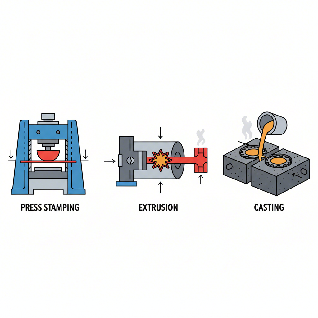
Creating aluminum body panels involves several distinct manufacturing processes, each dependent on a specific type of die design. The three primary methods are automotive stamping, aluminum extrusion, and aluminum die casting. Understanding the differences is crucial for selecting the right approach for a specific component, from a door panel to a structural frame.
Automotive Stamping Dies
Stamping is the most common process for large body panels like doors, hoods, and fenders. It involves shaping a flat sheet of aluminum between two halves of a die in a stamping press. The process is typically sequential, using a series of specialized dies. As detailed by automotive manufacturing experts, this progression includes several key stages. First, a drawing die performs the initial major shaping, stretching the flat blank to create the panel's primary 3D form. Next, trimming and piercing dies cut away excess material from the edges and create necessary holes for components like handles or lights. Following this, flanging dies bend the edges to create surfaces for assembly and add rigidity. Finally, restriking dies are used to sharpen contours and correct any springback, ensuring the panel meets exact dimensional tolerances. Leading suppliers in this field, such as Shaoyi (Ningbo) Metal Technology Co., Ltd., specialize in creating these complex, custom automotive stamping dies for major OEMs, ensuring high precision across high-volume production.
Aluminum Extrusion Dies
Extrusion is used to create parts with a constant cross-section, such as window frames, structural rails, and trim pieces. In this process, a heated aluminum billet is pushed through a die orifice. There are three main categories of extrusion dies. Solid dies, the simplest type, produce shapes with no enclosed voids, like angles or flat bars. Hollow dies are more complex and are used to create profiles with one or more enclosed voids, such as a square tube. These dies use a mandrel to form the internal cavity. Semi-hollow dies create profiles that partially enclose a void and are more complex to design than solid dies due to the delicate balance of metal flow required. The Aluminum Extruders Council notes that effective extrusion die design hinges on controlling metal flow speed by adjusting bearing lengths to ensure all parts of the profile exit the die uniformly.
Aluminum Die Casting
Die casting is ideal for producing complex, intricate aluminum parts by injecting molten metal into a steel mold (die) under high pressure. This process is often used for components like engine brackets, transmission housings, and structural nodes where high detail and precision are required. The dies are typically made in two halves that are locked together during injection and then separated to eject the solidified part. The design of these dies is highly complex, as it must manage the flow of molten metal, control cooling to prevent defects, and facilitate easy part removal.
| Process | Associated Die Types | Typical Automotive Applications |
|---|---|---|
| Stamping | Drawing, Trimming/Piercing, Flanging, Restriking | Hoods, doors, fenders, trunk lids, body sides |
| Extrusion | Solid, Hollow, Semi-Hollow | Bumper beams, roof rails, frame components, battery enclosures |
| Die Casting | Two-half steel molds (dies) | Engine blocks, transmission cases, shock towers, intricate structural nodes |
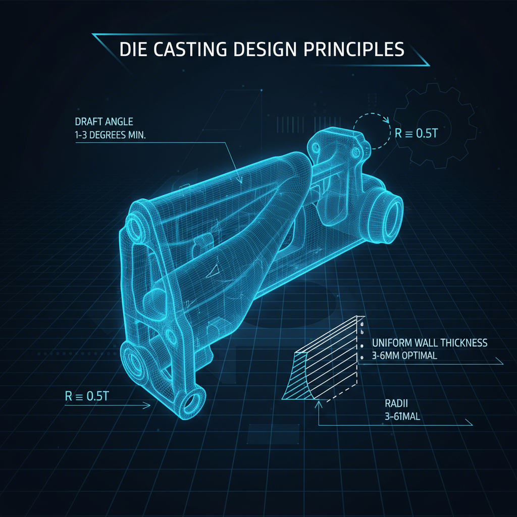
9 Critical Design Considerations for Aluminum Die Casting
Effective die casting requires more than just creating a cavity in the shape of a part. It involves a set of principles known as Design for Manufacturing (DFM), which aims to optimize the part for efficient, high-quality production. Based on a comprehensive aluminum die casting design guide, adhering to specific design rules is essential to prevent defects and reduce costs. These considerations collectively form the foundational rules of die design.
- Parting Line: This is the line where the two halves of the die meet. Its placement is a primary decision, as it affects where any excess material (flash) will form and must be trimmed. A well-placed parting line simplifies post-production finishing.
- Shrinkage: As molten aluminum cools, it shrinks (typically 0.4-0.6%). The die must be designed slightly larger than the final part to compensate for this. Shrinkage can also cause the part to grip internal features of the die, making ejection difficult.
- Draft: A draft is a slight taper applied to all surfaces parallel to the die's direction of movement. This angle, similar to that on a muffin pan, is crucial for allowing the cast part to be ejected easily from the die without damage.
- Wall Thickness: Walls should be as uniform in thickness as possible. Walls that are too thin can cause the molten metal to solidify before filling the mold completely, while overly thick walls waste material and increase cooling time, slowing production.
- Fillets and Radii: Sharp corners are problematic in die casting, as they can create turbulence in the metal flow and lead to weaknesses. Adding rounded internal corners (fillets) and external corners (radii) allows the metal to flow smoothly, increasing the part's structural integrity.
- Bosses: These are protruding features often used as mounting points. They must be designed carefully to maintain uniform wall thickness, often by coring out their center, to avoid defects like sink marks.
- Ribs: To add strength to a part without increasing wall thickness, designers can add thin structural supports called ribs. They also help guide the flow of molten metal into complex areas of the die.
- Undercuts: These are features that prevent the part from being directly ejected from the die. While sometimes necessary, they should be avoided when possible as they require complex and costly die mechanisms like side-cores to produce.
- Holes and Windows: Incorporating holes and windows directly into the die design eliminates the need for secondary drilling or milling operations. This saves significant time and cost but requires careful design to ensure proper metal flow around these features.
The Die Manufacturing and Tooling Process
Creating a die for aluminum body panels is a precise, multi-step process that transforms a block of tool steel into a high-performance manufacturing instrument. The journey begins with a digital design, where engineers use CAD (Computer-Aided Design) software to model the die and Finite Element Analysis (FEA) to simulate the metal flow and thermal behavior. This simulation helps identify potential issues before any steel is cut, optimizing the design for performance and longevity.
Once the design is finalized, the physical manufacturing begins. A block of H13 tool steel is typically machined using CNC (Computer Numerical Control) machines, which can execute complex cuts with extreme precision. For intricate features or very hard materials, Wire EDM (Electrical Discharge Machining) may be used. After machining, the die undergoes a critical heat treatment process to harden the steel, enabling it to withstand the immense pressures and temperatures of production. Finally, the surfaces are polished and sometimes coated with treatments like nitriding to enhance wear resistance and improve the flow of aluminum.
The die itself is part of a larger assembly known as the die stack or tooling package. This assembly, often called a die set, consists of two halves: the cover die and the ejector die. These halves are mounted into the die casting machine and separate to allow the solidified part to be removed. The complexity and size of this tooling stack influence the overall cost, which can vary significantly based on the profile's intricacy, whether it is hollow or solid, and the expected production volume. Proper maintenance, including regular cleaning and repolishing, is essential to manage wear and tear and extend the tool's operational life.
Frequently Asked Questions
1. What is the die design rule?
There isn't a single "die design rule," but rather a collection of best practices and principles often referred to as Design for Manufacturing (DFM). For die casting, these rules include critical considerations like establishing a proper parting line, incorporating draft angles for easy part ejection, maintaining uniform wall thickness, using fillets and radii to avoid sharp corners, and designing for material shrinkage. Following these guidelines helps ensure the manufacturability of the part, minimizes defects, and reduces production costs.
2. How to make an aluminium die?
Making a die for shaping aluminum is a sophisticated process. It starts with a digital design using CAD software, which is often validated with FEA simulations. A block of high-grade tool steel (like H13) is then precisely machined using CNC mills or Wire EDM to create the die's shape. The machined die undergoes heat treatment to harden it, followed by surface polishing and sometimes special coatings to improve durability and metal flow. The finished die is then assembled into a tooling stack with support components like backers and bolsters, ready for use in a press.
3. What does an aluminum extrusion die look like?
An aluminum extrusion die is typically a thick, circular disk made of hardened steel. In its center is a precisely machined opening, or orifice, that matches the desired cross-sectional shape of the final extruded profile. For solid shapes, it's a single plate. For hollow shapes, the die is more complex, often a multi-piece assembly (like a porthole die) that includes a mandrel to form the internal void as aluminum flows around it and welds back together before exiting the die.