 Small batches, high standards. Our rapid prototyping service makes validation faster and easier —

Mastering Automotive Die Casting Mold Design
TL;DR
Die casting mold design for the automotive industry is a high-precision engineering process for creating durable steel tools, known as dies. These molds are used to shape molten metal under intense pressure, producing complex and lightweight automotive components. A successful design is critically dependent on managing material flow, implementing effective thermal controls, and meticulously planning each component to ensure the final parts meet strict quality and performance standards.
Fundamentals of Automotive Die Casting Molds
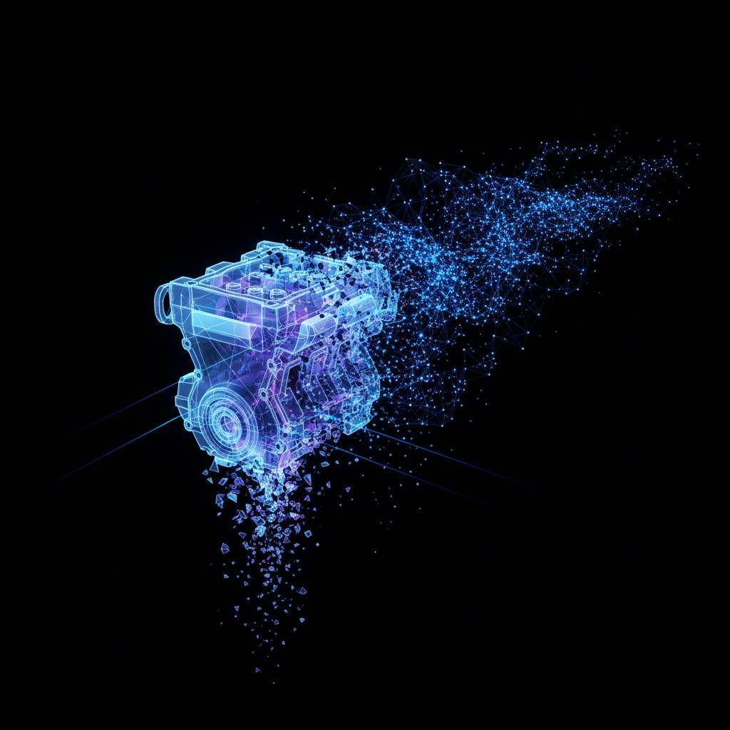
A die casting mold is a specialized, high-precision steel tool used in the die casting process. In this manufacturing method, molten metal alloys are injected into the mold's cavity under high pressure. The metal rapidly fills every detail of the cavity, cools, and solidifies to form a net-shape part. For the automotive industry, this process is indispensable. It allows for the mass production of components that are both intricate and structurally robust, which is essential for modern vehicle performance.
The role of die casting in enhancing vehicle performance cannot be overstated. By producing lightweight yet strong components, die casting directly contributes to improved fuel efficiency and better handling. According to an article by AutoCast Inc., a lighter vehicle requires less energy to move, resulting in lower fuel consumption and reduced emissions. This lightweighting is achieved without compromising strength, as the high-pressure injection process creates dense, durable metal structures capable of withstanding significant stress and vibration.
A wide array of critical automotive parts are produced through die casting. Common examples include:
- Engine Blocks: Die-cast engine blocks are lighter, have excellent dimensional accuracy, and facilitate better heat dissipation.
- Transmission Cases: These components benefit from the rigidity and precise dimensions of die casting, which ensures smooth gear shifting and efficient power transmission.
- Chassis Components: Parts like suspension brackets and steering knuckles are made using die casting to achieve high strength-to-weight ratios, enhancing both durability and ride comfort.
- Brake Components: The process is ideal for creating complex shapes for brake calipers, including internal channels for fluid and heat management.
Compared to other manufacturing processes, die casting offers significant advantages in cost-effectiveness and design flexibility for high-volume production. While processes like CNC machining offer high precision, die casting is faster and more economical for large quantities. Another key process in automotive manufacturing is metal stamping, which is ideal for forming sheet metal into body panels and structural components. For instance, specialized providers like Shaoyi (Ningbo) Metal Technology Co., Ltd. focus on creating custom automotive stamping dies, offering another avenue for producing high-precision metal parts for OEMs and Tier 1 suppliers. The choice between die casting and stamping ultimately depends on the part's geometry, material, and required production volume.
Anatomy of a Die Casting Mold: Core Components Explained
A die casting mold is a complex assembly of precisely engineered parts, typically split into a fixed (cover) half and a moving (ejector) half. Each component serves a specific function to ensure the molten metal is properly injected, shaped, cooled, and ejected. Understanding this anatomy is fundamental to designing a successful mold.
The primary components responsible for shaping the part are the Mold Cavity and Mold Core. The cavity is the hollow space that forms the external surfaces of the final part, while the core forms the internal features, such as holes or recesses. These are typically made from hardened tool steels like H13 to withstand the thermal and mechanical stresses of the casting cycle. The interaction between the cavity and core defines the final geometry of the cast component.
The delivery of molten metal is managed by the Runner System, which includes the sprue, runners, and gates. The sprue is the initial channel where molten metal enters the mold from the injection system. From there, runners distribute the metal to different areas of the mold. Finally, the gate is the narrow opening connecting the runner to the mold cavity, controlling the flow rate and direction as metal enters. The design of this system is critical for preventing defects like turbulence and premature solidification.
Once the part has solidified, the Ejector System is responsible for its removal from the mold. This system consists of ejector pins, plates, and return pins. The ejector pins push the casting out of the cavity without causing damage. Equally important are the Cooling and Venting Systems. Cooling channels are drilled throughout the mold to circulate a fluid (like water or oil), which regulates the temperature and reduces cycle time. The venting system provides small channels for trapped air and gases to escape the cavity as it fills with metal, preventing defects like porosity.
| Component | Primary Function | Common Material |
|---|---|---|
| Mold Cavity & Core | Forms the external and internal shape of the part. | H13, P20 Tool Steel |
| Runner System (Sprue, Runner, Gate) | Guides molten metal from the injector into the mold cavity. | Tool Steel |
| Ejector System | Pushes the solidified casting out of the mold. | Hardened Steel Pins |
| Cooling System | Regulates mold temperature to control solidification and cycle time. | N/A (channels within the mold) |
| Venting System | Allows trapped air and gases to escape the mold cavity. | N/A (small grooves or gaps) |

A Step-by-Step Guide to Designing an Automotive Die Casting Mold
Designing a die casting mold for automotive applications is a meticulous, multi-stage process that combines part analysis, fluid dynamics, and mechanical engineering. Following a structured approach is essential to create a tool that produces high-quality parts efficiently. The process can be broken down into several key steps, as outlined by guides from manufacturing experts like Prototool.
- Part Design Analysis: The process begins with a thorough analysis of the automotive part's 3D model. Designers evaluate features, geometry, and technical requirements to ensure manufacturability. This includes identifying necessary draft angles, fillets, and potential undercuts that might complicate ejection.
- Gate and Runner Design: Next, the system for delivering molten metal is designed. The gate and runner system must control the flow to fill the cavity evenly, minimizing turbulence that could cause defects. The size and location of the gate are critical for achieving a high-quality surface finish and structural integrity.
- Mold Base and Component Design: The mold base, which houses the cavity, core, and other components, is designed to fit the specifications of the die casting machine. This stage involves planning the layout of all internal elements, including sliders for undercuts and inserts for complex features.
- Cooling System Design: An effective cooling system is crucial for regulating temperature and minimizing cycle time. Cooling channels are strategically placed within the mold to ensure uniform cooling across the part, which helps prevent warping and other thermal defects.
- Venting and Ejection System Design: Proper venting is designed to allow air to escape the cavity as it fills with metal. Simultaneously, the ejection system, composed of ejector pins, is designed to safely and efficiently remove the solidified part from the mold without causing damage.
- Draft Analysis: A detailed draft analysis is performed on the 3D model. Draft is a slight taper applied to surfaces parallel to the mold's opening direction. This analysis ensures there are no undercuts or vertical walls that would prevent the part from being easily ejected from the mold. A minimum of 1-2 degrees is often recommended.
- Simulation and Verification: Finally, the complete mold design is verified using computer-aided engineering (CAE) software. This simulation models the metal flow, cooling, and solidification process, allowing designers to identify and correct potential issues like air entrapment, cold shuts, or porosity before the physical mold is manufactured.
Critical Design Considerations for Optimal Automotive Parts
Beyond the sequential design process, several fundamental principles must be integrated to ensure the production of high-quality, defect-free automotive components. These considerations, detailed in guides from sources like RapidDirect, focus on the geometry and structure of the part itself to optimize it for the die casting process. Adhering to these best practices prevents common manufacturing flaws and extends the life of the mold.
One of the most critical factors is Wall Thickness. It is essential to maintain a uniform wall thickness throughout the part whenever possible. Non-uniform sections cool at different rates, which can lead to shrinkage, porosity, and warping. If thickness variations are unavoidable, the transition should be gradual. Uniformity ensures a smooth metal flow during filling and controlled cooling, which is vital for dimensional stability.
Other key geometric considerations include Die Draft and Fillets. A draft, or taper, must be applied to all walls parallel to the die's opening direction to facilitate easy ejection of the part. Insufficient draft can cause drag marks or damage to the part during removal. Fillets, which are rounded internal corners, should be used instead of sharp edges. Sharp corners can cause stress concentrations in both the part and the mold, leading to cracks. Fillets also improve molten metal flow and make the tool more durable.
The Parting Line—the surface where the two mold halves meet—must be carefully chosen. Its placement affects where flash (excess material) may form and can influence the part's final appearance and tooling cost. Finally, features like Ribs and Bosses are often used to increase strength without adding excessive wall thickness. Ribs provide structural support, while bosses serve as mounting points. However, these features must be designed carefully to avoid creating thick sections that could cause cooling issues.
Pre-Production Design Checklist
- Uniform Wall Thickness: Are all walls as uniform as possible? Are transitions gradual?
- Sufficient Draft: Is there a draft angle on all vertical surfaces (typically 1-3 degrees)?
- Generous Fillets: Have all sharp internal corners been replaced with fillets?
- Optimal Parting Line: Is the parting line placed to minimize visual impact and simplify tooling?
- Properly Designed Ribs/Bosses: Are ribs and bosses designed to add strength without creating thick, hard-to-cool sections?
Achieving Precision in Automotive Mold Design
Mastering die casting mold design for the automotive sector is a blend of scientific principle and practical experience. The process is foundational to creating lightweight, strong, and precise components that define modern vehicle performance. From understanding the fundamental role of die casting in improving fuel efficiency to meticulously planning each component of the mold, every detail matters.
The key takeaways for any engineer or designer are to prioritize a structured design process, adhere to critical geometric principles like uniform wall thickness and proper draft, and leverage simulation tools to preemptively solve manufacturing challenges. By focusing on these core tenets, it is possible to create robust molds that deliver consistent, high-quality automotive parts while optimizing production efficiency and minimizing costly defects.
Frequently Asked Questions
1. What material is best for a die casting mold?
The most common materials for die casting molds are high-quality tool steels, such as H13 and P20. These materials are chosen for their excellent hardness, wear resistance, and ability to withstand the high temperatures and pressures of the die casting process, ensuring a long service life for the mold.
2. What is the primary advantage of die casting for automotive parts?
The primary advantage is the ability to mass-produce complex, lightweight, and dimensionally accurate parts with excellent strength-to-weight ratios. As explained by industry experts at Xometry, this helps automakers improve fuel efficiency, enhance vehicle performance, and maintain cost-effective manufacturing for high-volume production.
3. How does the cooling system affect the final part?
The cooling system is critical for controlling the solidification of the molten metal. A well-designed system with strategically placed channels ensures uniform cooling across the part, which prevents defects like warping, shrinkage, and hot spots. It also significantly reduces the cycle time, increasing overall production efficiency.