 Small batches, high standards. Our rapid prototyping service makes validation faster and easier —

Essential DFM Principles for Aluminum Extrusion Design

TL;DR
Design for Manufacturability (DFM) for aluminum extrusion is the engineering practice of optimizing a profile's design to ensure it can be produced efficiently, consistently, and cost-effectively. This process involves aligning the part's geometry, material choice, and tolerances with the capabilities of the extrusion process. The primary goal is to minimize production costs, reduce waste, and improve the final quality and performance of the extruded component.
Understanding the Core Principles of DFM for Aluminum Extrusion
Design for Manufacturability (DFM) is a foundational engineering practice focused on designing products in a way that makes them easy and economical to manufacture. When applied to aluminum extrusion, DFM bridges the gap between a theoretical design and a physically producible part. It is the process of proactively optimizing a profile's design by considering the real-world capabilities and limitations of the extrusion press, tooling, and downstream finishing processes. According to experts at Aluphant, a good extrusion design isn't just about the final shape; it's about making the profile easier to extrude, machine, and finish while maintaining high quality and controlling costs.
The core purpose of DFM is to identify and resolve potential manufacturing issues during the design phase, where changes are least expensive to implement. By aligning the design with the manufacturing process, engineers can prevent problems like die breakage, material flow issues, surface defects, and dimensional inaccuracies. This proactive approach avoids costly trial-and-error during production, shortens lead times, and improves the overall yield of acceptable parts.
The primary objectives of applying DFM principles to aluminum extrusion can be summarized as follows:
- Cost Reduction: By simplifying profiles, using standard alloys, and designing for faster extrusion speeds, DFM directly lowers tooling, material, and production costs.
- Quality Improvement: Designs optimized for manufacturability result in more consistent dimensional accuracy, better surface finishes, and superior structural integrity.
- Increased Efficiency: A manufacturable design allows for higher extrusion speeds, reduces scrap rates, and minimizes the need for secondary operations, streamlining the entire production workflow.
- Enhanced Reliability: By mitigating risks associated with complex or unbalanced profiles, DFM leads to a more stable and predictable manufacturing process, ensuring reliable delivery schedules.
Key Design Guidelines for Manufacturable Aluminum Profiles
Creating an aluminum profile that is both functional and manufacturable requires adherence to several key design principles. These guidelines are centered on controlling the flow of heated aluminum through the die to ensure stability, consistency, and efficiency. Ignoring these rules can lead to increased costs, production delays, and compromised quality.
1. Maintain Uniform Wall Thickness
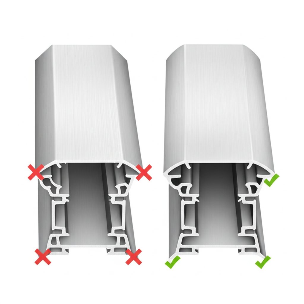
This is arguably the most critical DFM principle for aluminum extrusion. Aluminum will naturally flow through the path of least resistance, meaning it moves faster through thicker sections of a die compared to thinner ones. As noted in a comprehensive guide by Ya Ji Aluminum, significant variations in wall thickness cause unbalanced metal flow, which can lead to profile distortion, twisting, and internal stress. As a best practice, designers should aim for a wall thickness ratio of 2:1 or less. Where thickness changes are unavoidable, they should be gradual, using smooth tapers and generous radii to ease the transition.
2. Use Generous Corner Radii
Sharp internal and external corners are detrimental to the extrusion process. Internally, they create high-stress concentrations in the die, increasing the risk of cracking and premature wear. Externally, sharp corners are difficult to fill completely with material and can lead to surface defects. Adding fillets and radii (typically 0.5mm to 1.0mm or more) helps the aluminum flow more smoothly, reduces die stress, and improves the part's resistance to fatigue. This simple adjustment significantly extends die life and enhances the profile's overall quality.
3. Simplify Profile Geometry and Promote Symmetry
Complexity directly translates to cost and risk in extrusion. Highly intricate, non-symmetrical profiles are challenging to produce consistently. Symmetrical designs help balance the pressure and heat distribution across the die face, leading to more stable extrusions. When a complex profile is necessary, consider breaking it into two or more simpler, interlocking extrusions. While this may increase assembly steps, two easily produced parts are often more cost-effective than one that is difficult to extrude.
4. Design for Material and Process Limitations
The design must account for the specific aluminum alloy being used and the capabilities of the extrusion press. For instance, high-strength alloys in the 2xxx and 7xxx series are less extrudable than the common 6xxx series alloys. Furthermore, the profile's overall size, defined by its Circumscribing Circle Diameter (CCD), determines which press can be used. Designing within the capabilities of more common press sizes can increase supplier options and reduce costs. For specialized applications, such as in the automotive industry, partnering with a manufacturer that understands these nuances is crucial. Companies like Shaoyi Metal Technology offer services under strict IATF 16949 quality systems, providing expertise in creating strong, lightweight, and highly customized parts tailored to specific manufacturing constraints, as detailed on their page about automotive aluminum extrusions.
Common Pitfalls: How to Avoid Costly Design Errors
Even with a solid understanding of DFM principles, designers can fall into common traps that compromise manufacturability. Recognizing these pitfalls is the first step toward creating robust, cost-effective aluminum extrusion designs. Avoiding these errors not only saves money but also accelerates the time-to-market by preventing unnecessary tooling rework and production delays.
One of the most frequent mistakes is designing overly complex hollow or semi-hollow profiles. Hollow sections require sophisticated dies with internal mandrels that are expensive to create and maintain. They also necessitate slower extrusion speeds. Before committing to a hollow design, engineers should ask if the void is truly necessary. Often, a semi-hollow profile or two interlocking solid profiles can achieve the same functional goal with significantly lower tooling costs and higher production yields. Another common error is specifying tolerances that are tighter than functionally required. Over-tolerancing forces slower extrusion speeds, increases inspection costs, and leads to higher scrap rates without adding value to the final product.
To illustrate the impact of these choices, consider the following comparisons between poor and manufacturable design practices:
| Poor Design Choice (Problem) | Manufacturable Alternative (Solution) |
|---|---|
| Sharp internal corners create high stress on the die and can cause surface defects. | Add generous internal radii (e.g., >0.5mm) to improve metal flow and reduce die wear. |
| Drastic changes in wall thickness lead to uneven flow, distortion, and warping. | Maintain uniform walls or use gradual tapers to ensure balanced flow and thermal stability. |
| Deep, narrow channels are difficult to fill, trap air, and increase extrusion pressure. | Widen the channel or reduce its depth. Aim for a rib height-to-gap ratio of less than 4:1. |
| An overly complex, single-piece profile results in expensive tooling and low yield. | Split the design into two or more simpler, interlocking profiles that are easier and cheaper to extrude. |
| Specifying unnecessarily tight tolerances on all features increases cost without functional benefit. | Apply tight tolerances only to critical mating surfaces and use standard tolerances elsewhere. |
The Role of Material Selection in DFM
The choice of aluminum alloy and its temper is a critical DFM consideration that occurs early in the design process. This decision directly impacts not only the final part's mechanical properties—such as strength, corrosion resistance, and surface finish—but also its extrudability. Different alloys flow through a die at different rates and require different pressures and temperatures. Selecting an alloy that is poorly suited for the desired profile geometry can negate even the most carefully planned design.
The 6xxx series of alloys, particularly 6063 and 6061, are the workhorses of the extrusion industry for good reason. 6063 offers excellent extrudability and a superior surface finish, making it ideal for architectural and decorative applications where appearance is key. 6061 provides higher strength, making it a popular choice for structural components. While high-strength alloys from the 2xxx and 7xxx series offer superior mechanical performance, they are significantly more difficult and expensive to extrude. As a general DFM principle, designers should select the most extrudable alloy that meets the product's functional requirements.
The temper, which refers to the heat treatment process applied after extrusion, also plays a vital role. For example, a T4 temper provides good formability for post-extrusion bending, while a T6 temper offers maximum strength. Aligning the alloy and temper selection with both the manufacturing process and the end-use application is essential for a successful outcome.
| Alloy | Key Characteristics | Common Applications |
|---|---|---|
| 6063 | Excellent extrudability, superior surface finish, good corrosion resistance. | Window frames, door frames, decorative trim, pipe, tubing. |
| 6061 | Good strength, good machinability and weldability, good corrosion resistance. | Structural components, machine parts, fixtures, transportation. |
| 6005A | Medium strength, good extrudability, similar to 6061 but with better surface finish. | Railings, automotive components, structural members. |
From Design to Production: A DFM Summary
Integrating Design for Manufacturability into the aluminum extrusion process is not a restrictive measure but an enabling one. It empowers engineers to create innovative, functional, and economically viable products by aligning design intent with manufacturing reality. By focusing on principles such as uniform wall thickness, generous radii, profile simplification, and appropriate material selection, designers can significantly reduce tooling costs, accelerate production cycles, and improve the quality and consistency of the final part. These practices transform potential manufacturing challenges into opportunities for efficiency and optimization.
Ultimately, DFM is a collaborative effort between the designer and the manufacturer. Early engagement with an experienced extrusion supplier can provide invaluable feedback, helping to identify potential issues before they become costly problems. Adopting a DFM mindset ensures that the path from a CAD model to a finished, high-quality extruded component is as smooth and efficient as possible, delivering better products to market faster.

Frequently Asked Questions
1. What is the Design for Manufacturability (DFM) process?
Design for Manufacturability (DFM) is an engineering practice of designing products to be easier and more cost-effective to produce. In the context of aluminum extrusion, this involves simplifying, optimizing, and refining the profile design to align with the capabilities of the extrusion process, with the end goal of creating a better product at a lower cost.
2. What do Design for Manufacturing (DFM) guidelines focus on?
DFM guidelines for aluminum extrusion focus on a series of best practices aimed at ensuring a smooth and efficient manufacturing process. Key areas of focus include maintaining uniform wall thickness, using simple and symmetrical profiles, incorporating rounded corners, selecting appropriate alloys and tempers, and specifying realistic tolerances. These guidelines help reduce manufacturing defects and improve production speed and yield.
3. What is a DFM checklist?
A DFM checklist is a tool used by engineers to review a design for potential manufacturing issues before it is sent to production. For aluminum extrusion, a checklist would typically include criteria such as wall thickness variation, corner radii, tolerance analysis, alloy selection, and overall profile complexity. It serves as a systematic way to identify and mitigate risks early in the design stage.