 Small batches, high standards. Our rapid prototyping service makes validation faster and easier —

Designing Metal Stamping Dies That Run Right The First Time
Core Concepts and Die Anatomy Made Simple
What Metal Stamping Dies Do From Coil To Finished Form
Ever wondered how products like car panels or appliance parts get their precise shapes, time after time? That’s where metal stamping dies come in. These specialized tools are at the heart of stamping and pressing operations, transforming flat steel sheet into complex, repeatable parts with tight tolerances. But what is a die in manufacturing, and how do these tools work?
A stamping die is a precision tool that shapes sheet metal under press force to produce consistent parts.
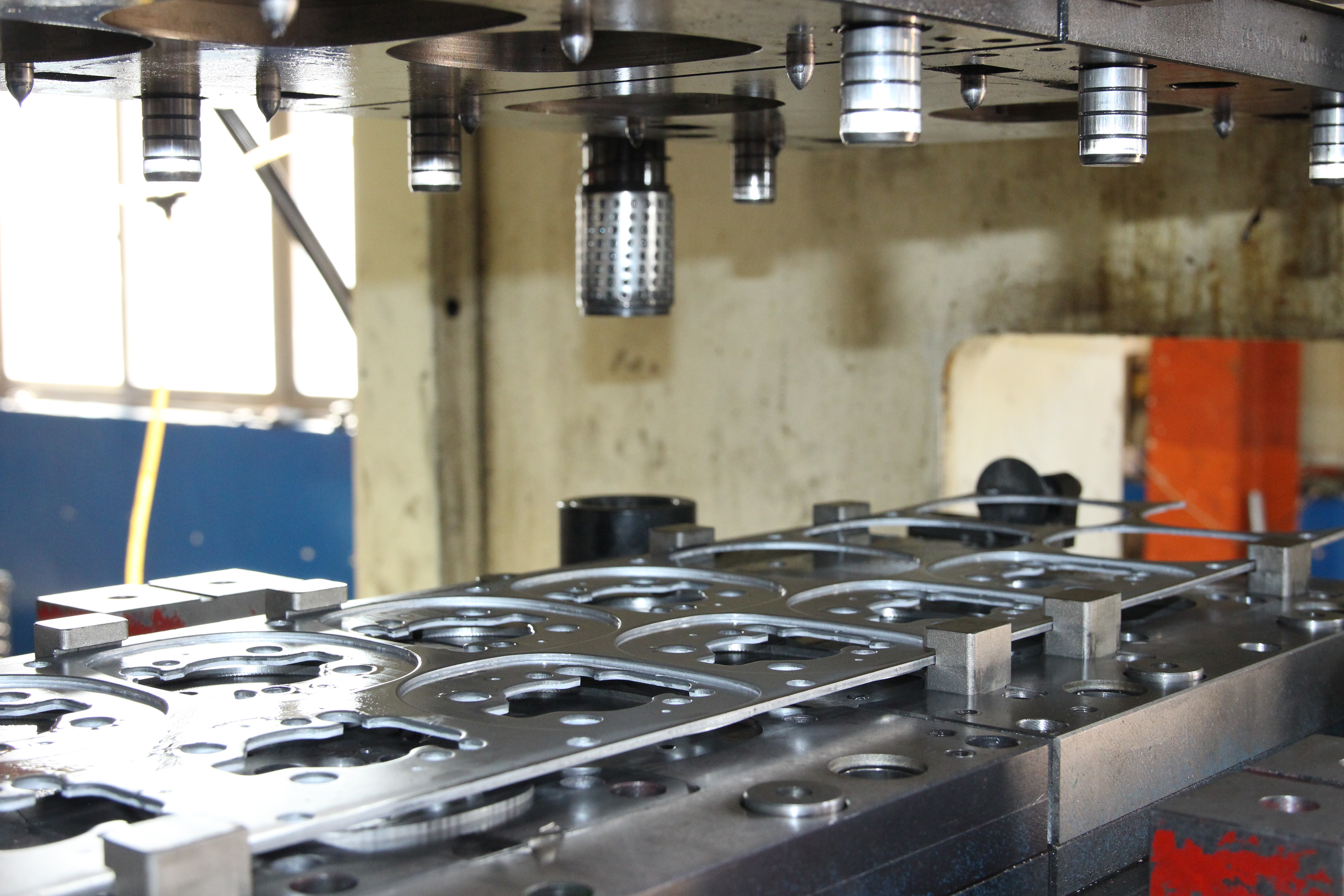
In the stamping process, sheet metal—often supplied as a coil—is fed into a press equipped with a die set. The press brings together two main die sections: the punch (which moves) and the die block (which stays fixed). When the press closes, the punch and die block work together to cut, form, or shape the metal. This cycle repeats rapidly, enabling high-volume production with reliable geometry and surface quality.
Inside A Stamping Die: Key Components And Functions
Imagine you’re looking inside a stamping die. You’ll notice several essential elements, each with a specific job to ensure accuracy and durability. Here’s a quick breakdown:
- Punch: The moving part that pushes into the metal to cut or form features.
- Die Block: The stationary section that supports the metal and provides the matching shape to the punch.
- Stripper Pad: Holds the sheet flat and strips it off the punch after each stroke.
- Pilots: Pins that precisely locate the sheet for each cycle, ensuring repeatability.
- Guide Pins and Bushings: Align the upper and lower die shoes for accurate operation.
- Springs: Provide the force needed for pads to hold, strip, or form the metal.
- Sensors: Monitor part presence, strip position, or detect misfeeds for process reliability.
From Press Stroke To Part: How The Stamping Process Flows
So, how does metal travel from coil to finished part? Here’s the typical stamping die cycle:
- Feed: Sheet metal is advanced into the die, often by an automated feeder.
- Locate: Pilots engage to position the sheet precisely.
- Clamp/Strip: Stripper pad holds the metal flat against the die block.
- Punch/Form: The press brings the punch down, cutting or forming the metal.
- Eject: The finished part or scrap is released from the die.
- Advance: The sheet moves forward for the next cycle.
This process is repeated at high speed, making stamping dies ideal for mass production. The use of metal punches and dies ensures that every part matches the required geometry, with minimal variation.
What Are Dies and How Do They Shape Metal?
You might hear terms like blanking, piercing, forming, drawing, and coining when discussing stamping dies:
- Blanking: Cutting the outer shape from the sheet.
- Piercing: Creating holes or cutouts within the part.
- Forming: Bending or shaping the metal without removing material.
- Drawing: Deepening or stretching the metal to form a cup or complex contour.
- Coining: Compressing the metal to create fine details or sharp edges.
Each operation relies on the right stamping die components and careful control of material flow.
Material Properties and Common Failure Modes
Material characteristics like thickness, strength, and surface finish play a huge role in how dies perform. For example, high-strength steel may require tougher die materials and more robust guide systems. Thicker sheets need larger clearances and stronger springs. Surface condition affects how smoothly the metal moves and how cleanly it separates during cutting. But even the best-designed dies can face challenges. Common failure modes include:
- Burrs: Rough edges from dull punches or poor clearance.
- Distortion: Warping caused by uneven forming forces.
- Splits: Cracks from overstretching during drawing or forming.
- Wrinkles: Excess metal flow due to low pad pressure or poor design.
Anticipating these risks is key to designing stamping dies that run right the first time.
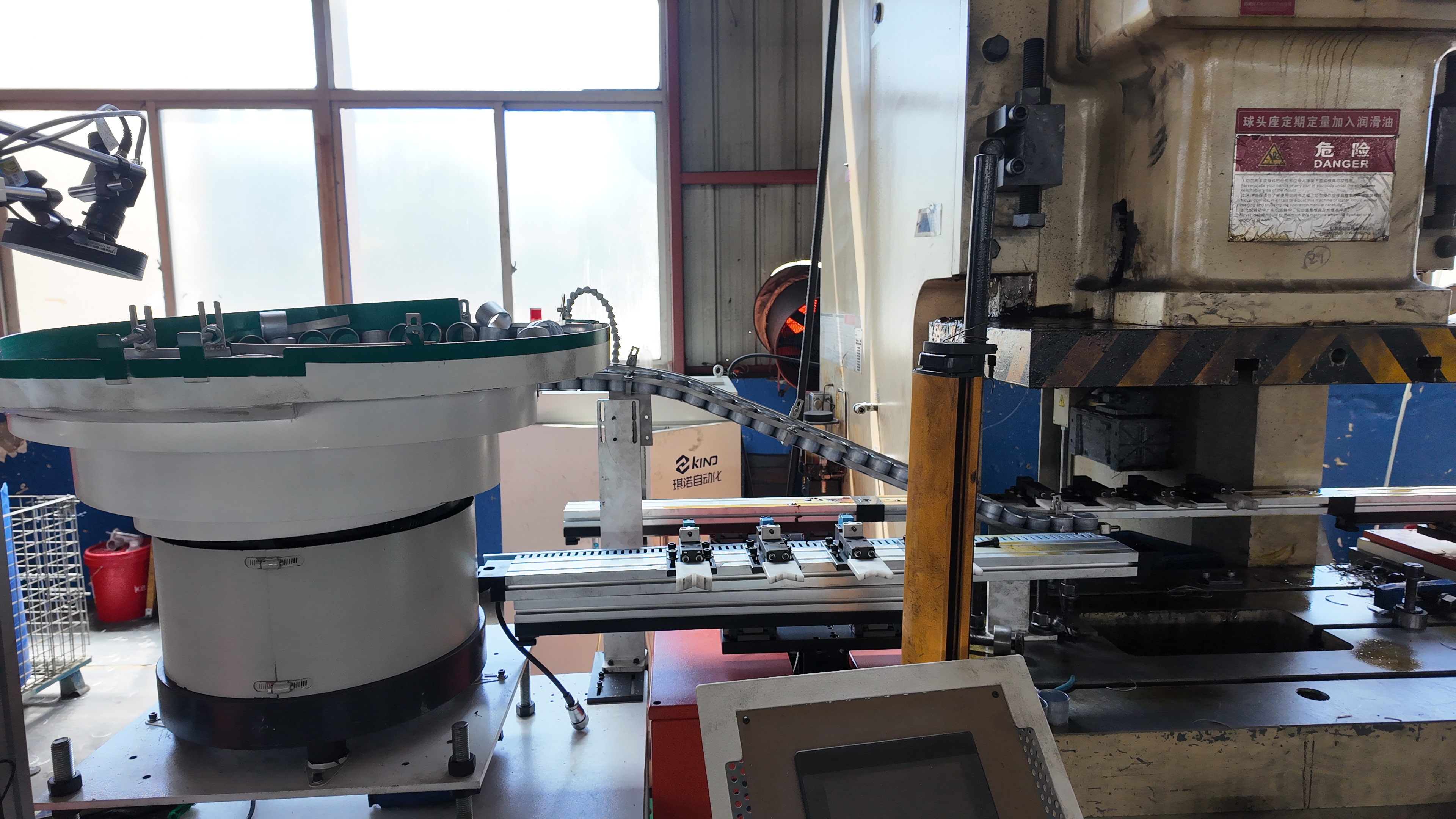
How Presses, Feeders, and Coil Handling Interface with Tooling
The performance of metal stamping dies depends not just on the die itself, but also on the entire system around it. Presses supply the force and motion; feeders advance the sheet; and coil handling equipment ensures smooth, consistent material delivery. All these elements must be aligned and synchronized for efficient stamping and pressing. Understanding what are dies and how they interact with presses and material handling is the foundation for successful, repeatable production. As you move through this guide, you’ll see how each detail—big or small—matters in the world of metal punches and dies.
Die Types and Selection Criteria for Metal Stamping Success
Die Types At A Glance: From Stage To Progressive
When you’re faced with a new sheet metal pressing project, you might wonder: which die type is the best fit for your needs? The answer depends on your production volume, part complexity, and budget. Let’s break down the main types of stamping dies and see how they compare in real-world applications.
| Die Type | Setup Complexity | Cycle Rate | Scrap Rate | Changeover Effort | Typical Part Families |
|---|---|---|---|---|---|
| Single-Station (Stage) | Low | Slow | Higher | Easy | Simple shapes, prototypes, low-volume steel sheet stamping |
| Compound | Moderate | Medium | Low | Moderate | Flat parts needing blanking & piercing in one hit |
| Progressive | High | Fast | Low | Complex | Automotive stamping dies, high-volume, complex geometry |
| Transfer | High | Medium | Low | Complex | Large, deep-drawn, or 3D parts |
When To Choose Progressive Dies Versus Transfer Lines
Imagine you’re launching a new automotive component. If it’s a flat part or has features that can be formed sequentially, a progressive die is often the go-to. Progressive dies feed a metal strip through a series of stations, each performing a specific operation—think blanking, piercing, forming, and more—before the finished part is cut free. This makes progressive die stamping ideal for high-volume runs, tight tolerances, and consistent quality, especially for complex steel stamping dies. But what if your part needs deep drawing, or has 3D features that can’t be supported by a carrier strip? That’s where transfer dies shine. In transfer die stamping, the part is separated from the strip early and moved mechanically or manually between stations. This approach is perfect for large, intricate parts—like frames or shells—where each station can perform a unique operation, including forming, bending, or even assembly. Transfer dies offer greater flexibility for part geometry, but typically require more sophisticated automation and setup. Compound dies sit between these two: they combine piercing and blanking in a single stroke at one station, making them efficient for flat parts that require both features but don’t need the complexity of a progressive line. For small-batch or frequently changing jobs, a single-station die can be the most cost-effective solution, thanks to its low setup time and flexibility.
What Components Change Across Stamping Die Architectures
No matter which type you choose, certain components are always present in die manufacturing:
- Punch – Forms or cuts the metal
- Die Block – Supports and shapes the workpiece
- Stripper – Removes the part from the punch
But as you move from simple to advanced dies, you’ll notice specialized additions:
- Pilots – Precisely locate strip position (critical in progressive dies)
- Carriers/Stock Guides – Support and guide the metal strip (used in progressive and compound dies)
- Transfer Fingers/Lifters – Move parts between stations (unique to transfer dies)
- Cams – Enable lateral or angled forming/piercing
- Sensors – Detect misfeeds, part-out, or tool wear (increasingly common in all die types)
For example, in progressive dies, pilots and sensors ensure each sheet metal pressing operation is perfectly synchronized. In transfer dies, lifters and transfer fingers handle the movement of individual blanks, enabling more complex 3D forms than strip-fed dies can achieve.
Choosing the right die in manufacturing is about matching process capability to your part’s geometry, volume, and quality needs. The wrong choice can mean wasted material, excessive scrap, or costly changeovers.
Which Die Type Is Right For You?
To sum up:
- Single-station dies are best for low-volume, simple parts or prototypes.
- Compound dies handle flat parts needing multiple features in one hit.
- Progressive dies excel at high-volume, multi-step production with consistent quality—think automotive stamping dies or electronics.
- Transfer dies enable complex, deep-drawn, or 3D parts by moving blanks from station to station.
Material matters too: softer metals like aluminum suit standard dies, while tougher steels demand robust, wear-resistant tooling. As you plan your next project, consider your priorities—speed, flexibility, part complexity, and budget. The right choice of stamping die architecture will set the stage for efficient, high-quality production—and a smooth transition to the next phase: optimizing your design for manufacturability. Ready to dig into DFM rules that prevent rework? Let’s explore how to design features that run right the first time.
DFM Rules That Prevent Rework in Stamping Die Design
Are you tired of costly tryouts, unexpected scrap, or last-minute design changes in your sheet metal die projects? Getting the details right at the design stage is the key to dies and stamping processes that run smoothly from day one. Let’s break down practical DFM (Design for Manufacturability) rules—organized by operation—that will help you avoid common pitfalls and deliver consistent, high-quality parts.
Blanking and Piercing: Clearance and Edge Quality
When you’re blanking or piercing, the distance between the punch and die (called clearance) is crucial. Too tight, and you risk tool wear and edge cracks; too loose, and you get burrs and distortion. So, how do you choose the right clearance? - For mild steels, clearances typically start around 6–10% of sheet thickness per side, but as you move to higher-strength steels (like AHSS), clearances can increase up to 16% or more. The optimal value depends on sheet thickness, tensile strength, and even your press’s rigidity. Always check your plant or supplier’s standards for exact values (AHSS Insights). - Edge quality matters for downstream forming. A clean burnish zone with a smooth transition to fracture is ideal. Excessive burrs or secondary shear zones signal that your clearance or punch condition needs attention. - For high-strength steel, use engineered tool steels and consider a beveled or rooftop punch to reduce cutting force and improve edge ductility.
| Operation | Key Parameter | How To Choose | Common Pitfalls | Your Plant Standard |
|---|---|---|---|---|
| Blanking/Piercing | Clearance (%) | Scale with thickness & strength | Burrs, edge cracks, excessive tool wear | |
| Piercing | Hole/Slot Size | Min. diameter ≥ material thickness | Distorted or unpunched holes | |
| All | Edge Quality | Uniform burnish/fracture zone | Splits, poor formability |
Bend Radii, Reliefs, and Feature Spacing That Work
Ever wonder why some bends crack or distort while others look perfect? The answer often lies in your choice of bend radius and relief features. Here’s what to watch for in sheet metal stamping design: - For ductile materials, keep the inside bend radius at least equal to the material thickness. For harder or heat-treated alloys (like 6061-T6 aluminum), you may need 4x thickness or more. Add bend reliefs at the edge of bends—these small notches or cutouts prevent stress concentration and cracking. Aim for relief width at least half the sheet thickness. - Place holes and slots away from bends: at least 2.5x thickness plus one bend radius from the bend line, and 1.5x thickness from edges. This protects features from distortion during the stamping metal process.
| Operation | Key Parameter | How To Choose | Common Pitfalls | Your Plant Standard |
|---|---|---|---|---|
| Bending | Inside Radius | ≥ thickness (ductile); ≥ 4x (hard) | Cracks, springback | |
| Bend Relief | Relief Width | ≥ 0.5x thickness | Tearing, edge splits | |
| Holes/Slots | Distance from Edge/Bend | Follow spacing guidelines | Distortion, misshaped holes |
Drawing and Flanging: Geometry That Resists Splits
Drawing (deep forming) and flanging can be especially sensitive to material properties and die geometry. Here’s how to keep splits and wrinkles at bay in your stamping process in manufacturing: - Use draw beads and carefully designed addendum geometry to control metal flow and prevent wrinkles or splits. - For high-strength steels, expect more springback—counteract this by using larger radii and, if needed, overbending strategies. - Embossing and coining require careful depth control. As a rule of thumb, emboss depth should not exceed three times the material thickness to avoid tearing (Five Flute).
| Operation | Key Parameter | How To Choose | Common Pitfalls | Your Plant Standard |
|---|---|---|---|---|
| Drawing | Draw Beads/Addendum | Optimize for material flow | Splits, wrinkles, uneven wall thickness | |
| Embossing | Max Depth | ≤ 3x thickness | Tearing, surface defects |
Checklist Before Tool Release
Before you send your metal stamping die design to production, run through this checklist to catch issues early:
- Datum strategy robust for all critical features
- Carrier and strip design supports weakest stages
- Sensor plan covers misfeed, part-out, and tool wear
- Lubrication plan matches material and forming severity
- Scrap evacuation and slug management mapped out
Tight tolerances belong on functional features only; over-tolerancing drives unnecessary tool complexity.
Common Defects and Preventive Actions
Even with the best stamping die design, defects like burrs, splits, wrinkles, and surface strains can occur. These are often tied to:
- Improper clearance or punch/die wear (burrs, edge cracks)
- Insufficient reliefs or tight radii (splits, tearing)
- Poor lubrication or misaligned dies (surface marks, wrinkles)
- Incorrect feature spacing (distortion, misshaped holes)
Addressing these at the DFM stage minimizes rework and scrap, saving time and cost down the line.
Why DFM Decisions Matter for Simulation and Tryout
Imagine discovering a split or wrinkle during tryout—frustrating and expensive, right? By following these DFM rules, you set the stage for accurate simulation results and a smoother path through the stamping metal process. In the next section, we’ll see how digital workflows and forming simulation can further close the loop, ensuring your stamping process in manufacturing hits the mark the first time.
Progressive Die Layout and Strip Development
From Part to Strip: How to Plan Stations
When you first see a progressive die in action, it looks like a well-choreographed dance—each station performing its own move, transforming a coil of stamped steel sheet into finished parts. But how do you go from a flat drawing to an efficient strip layout? The answer lies in understanding how to break down your part’s geometry into a sequence of stamping and die cutting operations, each assigned to a specific station in the die process. Imagine you’re designing a part with holes, bends, and flanges. You’d start by mapping the process:
- Pierce small holes and slots first—early stations handle features that don’t affect strip strength.
- Form and bend critical shapes in the middle—these operations require a stable carrier for support.
- Perform final cut-off last—the finished part is separated from the strip only after all features are complete.
This sequencing safeguards feature quality and keeps the strip robust throughout the die processing sequence. According to AutoForm, strip layout development is all about defining the number of stations, the sequence of operations, and optimizing material use.
Pilots, Carriers, and Timing That Keep the Strip Stable
You’ll notice that strip stability is the backbone of any successful progressive die. Pilots—precision pins that engage pilot holes in the strip—lock the material in place before each stroke, ensuring repeatable accuracy. Carriers, or webs, are the sections of material left between parts to hold the strip together as it advances. These must be strong enough to support the part through even the weakest forming stage. Here’s a simplified “Strip Bill of Stations” table to help visualize the breakdown:
| Station No. | Operation | Feature(s) | Feed Pitch | Sensors | Notes |
|---|---|---|---|---|---|
| 1 | Piercing | Pilot holes, small slots | Set by part length + carrier | Presence detection | Start with features that don’t weaken strip |
| 2 | Bending | Flanges, forms | Same as above | Stripper down | Ensure carrier supports formed area |
| 3 | Cutting/Forming | Contours, emboss | Same as above | Part-out | Monitor for slug accumulation |
| 4 | Cut-off | Final part separation | Same as above | Part-out | Check for bypass notches sheet metal forming purpose |
Timing is critical: pilots must engage before the punches descend, and sensors can be set to detect misfeeds or missed slugs. If your design includes lateral features, cams may be needed to drive side-action punches—just another example of how the stamp die adapts to complex part needs.
Optimizing Nesting and Scrap Flow
Sounds complex? It’s all about maximizing material usage and minimizing waste. Part nesting—arranging parts within the strip to use as much of the material as possible—can have a dramatic impact on costs. You’ll want to consider not only how parts are spaced, but also how the grain direction of the metal affects forming, especially for high-strength alloys. Sometimes, you can even nest multiple part types in the same strip, as long as their production volumes and forming requirements align (The Fabricator). Scrap management is equally important. Slug retention features, vacuum or air blow-off systems, and anti-backup notches keep the die running clean and prevent jams. Always plan for how scrap will be evacuated at each stage.
- Feed coil into die
- Pierce pilot holes and features
- Form bends and flanges
- Cut out the finished part
- Scrap is managed and removed
Plan the carrier to support the weakest stage of the part—strip stability drives dimensional stability.
When you design a progressive die layout, every detail—from pilot hole spacing to bypass notches sheet metal forming purpose—affects the robustness and repeatability of the die process. By combining thoughtful sequencing, strong carriers, and smart scrap management, you’ll set the stage for reliable, efficient production with every stroke of the metal stamping tool. Ready to see how digital workflows and simulation can further optimize your strip layout and reduce tryouts? The next section explores how technology closes the loop for modern die processing.
Simulation and Digital Workflow That Cuts Tryouts
When To Use Forming Simulation And What To Expect
Ever wish you could predict stamping defects before the first die is even built? That’s the promise of modern forming simulation—a digital approach that helps you dial in your sheet metal stamping process before a single tool hits the press. By simulating every stage of the stamping manufacturing process, you can spot risks, optimize part geometry, and reduce costly shop-floor tryouts.
Forming simulation is most valuable when you’re dealing with new materials (like advanced high-strength steel or aluminum), complex part shapes, or tight tolerance requirements. Imagine uploading your 3D CAD part, assigning a material card (with accurate strength curves), and virtually running the part through each die operation. The software then predicts thinning, thickening, wrinkling, and springback—giving you a clear map of where to expect trouble and how to adjust your design or process before any steel is cut.
| Input | What It Informs | Typical Output |
|---|---|---|
| 3D CAD Part & Addendum | Defines geometry and forming sequence | Final part shape, feature locations |
| Material Card (strength curve, n-value) | Bend radii, draw depth, springback risk | Thinning/thickening maps, FLD, springback vectors |
| Friction/Lubrication Model | Lube selection, draw bead tuning | Wrinkling, galling, material flow |
| Press Speed Profile | Die wear, surface finish, wrinkling | Cycle time, force curves |
| Binder/Blank Holder Force | Wrinkle and split control | Wrinkle risk, splits |
| Draw Bead Settings | Material flow, wall thickness | Wall thickness variation, draw depth |
By integrating these inputs, simulation software helps you optimize the stamping technology for each part, saving time and cost compared to traditional trial-and-error tryouts.
Springback Compensation and Overbend Workflows
When stamping high-strength steel or aluminum, you’ll notice parts often “spring back” after forming—meaning the final shape doesn’t quite match the die. This is where digital springback compensation comes in. Using simulation, you can predict how much the part will move after forming, then adjust your die surfaces (sometimes called “overbend” or “morphing”) so the final part lands within tolerance. The process typically involves:
- Simulating the initial forming operation and measuring predicted springback
- Adjusting die geometry in the virtual model (compensation)
- Re-running the simulation to validate results
- Iterating until the part meets spec
It’s important to replicate real-world press and die conditions in your simulation—right down to how the part is fixtured for measurement. According to FormingWorld, accurate compensation requires matching physical and digital setups, including binder gaps, draw bead locations, and even the material batch. By doing so, you minimize the “difference” between digital and shop-floor realities, making your manufacturing stamping process far more predictable.
Blank Development and Trim Line Iteration
Developing the right blank shape—essentially, the starting sheet profile before forming—is critical in the sheet metal stamping process. In the past, this could take days of trial and error, but with simulation, you can iterate rapidly. Here’s how it works:
- Start with an initial blank outline based on CAD geometry
- Virtually form the part in simulation
- Compare the formed part to the target shape using measurement tools (CMM or digital gauges)
- Adjust the blank shape based on where material is stretching or compressing
- Repeat until the formed part matches the required tolerance
This digital approach, as highlighted by StampingSimulation, can cut weeks off your development timeline and produce a more accurate trim profile—especially for complex parts or when using cold stamping techniques.
- CAD Model Preparation
- Simulation Setup (material, friction, press data)
- Virtual Tryout (form, trim, springback)
- Compensation (adjust die/blank geometry)
- CAM Toolpath Generation
- Physical Tryout
- Measurement (CMM, laser scan)
- Update Simulation/Tooling
Investing simulation time upstream moves cost from unpredictable tryouts to predictable engineering.
Best Practices for Digital Workflow Integration
- Always source material cards from suppliers or trusted public databases. If unavailable, document all model assumptions for future reference.
- Integrate press data (servo profiles, force curves) early—this ensures your simulation matches real-world stamping technology.
- Sync CAM postprocessors with validated die geometry to avoid discrepancies during machining.
- Use closed-loop feedback: after each physical tryout, feed measurement data back into your simulation to refine compensation and accelerate convergence.
By embracing this digital workflow, you’ll notice fewer surprises in the shop, reduced tryout loops, and more robust, repeatable results from your metal stamping process. As you move forward, keep in mind that integrating simulation with your die design and production planning is a cornerstone of modern manufacturing stamping—and a key to staying competitive in today’s fast-evolving industry.
Next, we’ll explore how modern press technology and line configurations impact die design and shop-floor results.

Modern Presses and Their Impact on Die Design
Servo Press Advantages for Forming and Springback Control
When you hear the term “servo press,” you might picture high-tech equipment with digital controls—and you’d be right. Servo presses have revolutionized the metal stamping manufacturing process by giving designers and operators unprecedented control over the press stroke. Unlike traditional mechanical presses, which run at a fixed speed and motion profile, servo presses use programmable servo motors to control slide position, speed, and even dwell time at the bottom of the stroke.
Why does this matter for stamping sheet metal? Imagine forming advanced high-strength steel or aluminum. These materials are prone to springback—where the part flexes back after forming—leading to out-of-tolerance shapes. With a servo press, you can slow down or pause the ram at bottom dead center, giving the material time to set and reducing springback. You can also fine-tune the speed profile to minimize wrinkling or thinning during complex forms. This flexibility is especially valuable for intricate parts or when running a high mix of materials and geometries.
-
Design impacts for servo presses:
- Customizable motion profiles for each part and operation
- Optimized lubrication strategy due to variable speeds
- Reduced need for complex die mechanisms (like cams) as motion can be digitally programmed
- Greater control over bead tuning and springback compensation
- Enhanced sensorization plan—integrate sensors to monitor force, position, and part-out in real time
- Potential for simpler scrap evacuation due to controlled motion
High-Speed Pressing for Thin and Electrical Steels
Ever wondered how manufacturers produce thousands of small, precise electrical contacts or thin steel components per minute? That’s the world of high-speed presses—a specialized class of die stamping machines designed for maximum throughput. These presses are ideal for pressing and stamping thin-gauge metals, such as copper alloys (for connectors) or electrical steel (for motor laminations).
But running at speeds up to 1,500 strokes per minute brings unique challenges. Punch-to-die alignment must be flawless to avoid tool damage or part defects. Lubrication needs to be perfectly tuned to prevent galling or overheating. Slug management—removing tiny pieces of scrap metal—is critical, as even a single mismanaged slug can cause a catastrophic die crash at high speeds. Dies for these applications often incorporate advanced coatings and surface finishes to withstand rapid cycling and abrasive wear, especially when dealing with steel stamping or hard alloys.
-
Design impacts for high-speed presses:
- Precision die alignment and robust guiding systems
- Specialized lubrication channels and materials
- Slug retention features and high-speed scrap evacuation systems
- Optimized stripper force to prevent part sticking
- Close attention to die wear patterns and surface treatment selection
- Enhanced sensorization for real-time monitoring
Tandem and Transfer Lines: Implications for Dies
Now, picture a row of presses, each performing a different operation on a large automotive panel. That’s a tandem or transfer line—a configuration where the part moves from one die to another, either by hand, robot, or automated grippers. These systems are commonly used for large, deep-drawn parts or when part geometry is too complex for a progressive die.
In transfer lines, the die design must account for gripper or transfer finger clearance, robust part locating features, and added sensors to ensure every part is in the right place at the right time. The dies are often larger and heavier, with features to accommodate robotic handling and quick changeover. Synchronization between presses and transfer mechanisms is critical, as a mistimed move can lead to part misfeeds or damage.
-
Design impacts for tandem/transfer lines:
- Dedicated locating features for consistent part placement
- Gripper/transfer finger clearance built into die geometry
- Additional sensors for part presence, misfeed, and transfer status
- Robust die construction to handle large parts and repeated handling
- Quick-change features to minimize downtime between runs
- Advanced scrap evacuation to prevent jams across multiple stations
Comparing Press Technologies: What’s Right for Your Die?
| Press Type | Motion Control | Typical Parts | Die Wear Considerations |
|---|---|---|---|
| Servo Press | Fully programmable, variable speed & dwell | Complex forms, high-mix, high-strength steels, aluminum | Lower wear due to optimized motion; sensitive to lubrication and sensor setup |
| High-Speed Mechanical Press | Fixed cycle, extremely fast | Thin-gauge, electrical steels, connectors | High wear rates; requires advanced coatings and frequent maintenance |
| Tandem/Transfer Line | Coordinated, multi-press synchronization | Large, deep-drawn automotive panels | Heavy-duty dies; focus on alignment, handling, and quick changeover |
Press motion is a design variable—dies that assume constant speed leave quality on the table.
Material Stack-Ups and Surface Finish: Why Technology Choice Matters
Your choice of press technology isn’t just about speed or flexibility—it directly impacts how you design for different materials. High-strength steels and aluminum alloys, common in modern automotive and appliance applications, demand careful control of forming speed, lubrication, and die surface finish. Servo presses allow you to tailor motion profiles to minimize thinning and control springback, while high-speed presses require robust coatings and precision alignment to handle aggressive cycling. For tandem lines, the focus shifts to robust construction and reliable material handling, especially for large, multi-stage steel stamping operations.
In the end, matching your die design to the capabilities of your chosen press—whether a programmable servo, a lightning-fast die-stamping machine, or a coordinated transfer line—ensures you get the best combination of quality, efficiency, and tool life. As you plan your next metal pressing process, consider how each technology shapes not only the die, but also your entire production strategy.
Next, we’ll map out the full tooling lifecycle, from initial design to sustained production—ensuring your dies deliver quality and uptime from the very first hit.
Die Build Lifecycle and Shop Workflow
Design To Build Workflow And Checkpoints
Ever wondered how a dies production project moves from a simple sketch to a robust tool running thousands of cycles in the press? The answer lies in a structured, step-by-step workflow that brings together engineering, manufacturing, and quality teams. Let’s break down the typical journey of a standard die in the die making industry:
- Requirements & DFM Review: The process starts with a detailed review of the part print and manufacturing feasibility. The designer works closely with engineering to confirm that features, tolerances, and materials are suitable for stamping. This is where what is dies in manufacturing becomes more than a definition—it’s the alignment of part intent with process capability.
- Detailed Die Design: Using CAD, the designer creates a comprehensive model and drawing set, specifying every punch, die block, stripper, and guide. Documentation includes strip layouts, bill of stations, and critical-to-quality features.
- CNC/CAM Programming: Programmers translate the design into machine code for CNC milling, EDM, or turning. Tool paths are optimized for accuracy and surface finish, especially in cutting and forming areas.
- Machining, EDM, and Polish: Toolmakers fabricate each die component, focusing on precision surfaces and tight tolerances. Machining die features for critical edges or radii is essential for both tool life and part quality.
- Heat Treatment & Coating: Certain components receive heat treatment for hardness and wear resistance, followed by coatings to reduce friction or galling—key for high-volume dies manufacturing.
- Assembly: All die components are assembled, shims are set for proper clearances, and guides are checked for alignment. Assembly documentation is updated for traceability.
- Bench Debug: Before moving to the press, the assembled die undergoes bench checks for fit, function, and safety.
- Press Tryout: The die is installed in a press, and trial runs are performed. The tryout press operator and metrology team measure initial parts, looking for defects or deviations.
- Part Measurement & Updates: Using CMMs or gauges, the quality engineer verifies dimensional accuracy. If needed, the die is adjusted and revalidated—often in several loops.
- Run-at-Rate & Handoff: Once the die consistently produces good parts at production speed, it’s handed off to the shop floor with a preventive maintenance (PM) plan.
This sequence ensures that every die for manufacturing is built right the first time, minimizing costly surprises during launch.
Tryout Validation and Dimensional Signoff
Imagine you’ve reached the tryout stage. Here, cross-functional teamwork is critical: the designer, toolmaker, tryout press operator, and quality engineer all play a part. The goal? Validate that the die produces parts within tolerance, meets surface finish targets, and holds up to production demands. For cutting areas, a smooth, burr-free edge and minimal die roll are signs of a well-machined die. For forming features, uniform surface finish and consistent geometry are key. Tolerance classes may vary by area—cutting edges often require tighter control than deep-forming pockets. Plant standards or references like U-Need PM can guide these requirements.
| Artifact | Description | Owner |
|---|---|---|
| Strip Layout | Station-by-station process map | Designer |
| Bill of Stations | List of all operations and features | Designer |
| PPAP/ISIR | Production Part Approval/Initial Sample Report as required | Quality Engineer |
| Measurement Reports | Dimensional data from CMM or gauges | Metrology |
| Maintenance Schedule | Intervals and tasks for PM | Toolmaker/Production |
| Setup Sheets | Press settings, lubrication, sensor I/O | Tryout Operator |
| Spare Detail List | Critical replacement parts | Toolmaker |
Measure early and often—metrology drives fast convergence in tryout.
Preventive Maintenance and Repair Planning
What keeps a die running reliably for years? The answer is a proactive maintenance strategy, tailored to part volume, material type, and observed wear patterns. According to industry best practices:
- Routine Inspections: Schedule regular checks for wear, cracks, or misalignment—especially on cutting and forming surfaces.
- Sharpening and Reconditioning: Cutting edges and form features should be re-sharpened before significant wear impacts quality.
- Lubrication: Use the correct lubricant for die materials and part alloys, and follow a documented schedule.
- Alignment and Calibration: Check and adjust shims, guides, and pressure settings to maintain dimensional accuracy.
- Training: Ensure operators and maintenance staff are trained on inspection, lubrication, and safe handling of dies.
For high-volume dies or abrasive materials, increase inspection and sharpening frequency. Predictive maintenance—using sensors or monitoring die cycles—can further reduce unplanned downtime and extend tool life.
By following this lifecycle—starting with a robust design and ending with disciplined maintenance—you’ll maximize tool life and part quality. In the next chapter, we’ll shift focus to procurement and supplier selection, helping you budget and source the right partner for your next stamping project.

Procurement and Cost Drivers Made Practical for Metal Stamping Dies
What Drives Tooling Cost and Lead Time?
When you start sourcing custom metal stamping dies, you’ll quickly notice that prices and timelines can vary widely. Why? Because every die project is shaped by a unique set of factors. Imagine two parts: one is a simple bracket, the other a complex automotive panel. The cost and delivery time for their dies will be worlds apart. Here are the key drivers:
- Part Complexity: More features, tight tolerances, or intricate shapes increase engineering and machining hours.
- Die Type: Progressive dies (often used by progressive die manufacturers) and transfer dies require more stations and design time than single-hit or compound dies.
- Material and Coatings: Harder or abrasive materials demand premium tool steels and specialized coatings, adding to cost.
- Tolerance & Surface Finish: Higher precision or cosmetic requirements require more time for finishing and validation.
- Sensorization & Automation: Adding sensors or automation for quality control raises both upfront and maintenance costs.
- Validation & Documentation: Extensive inspection plans, PPAP/ISIR, or customer audits extend lead times.
- Spares & Maintenance: Planning for spare parts and ease of repair can increase initial investment but pays off in uptime.
- Expected Tool Life: Dies designed for millions of cycles require robust construction and may justify higher costs.
According to industry experts, early DFM collaboration with your stamping dies manufacturer can reduce tooling costs by 10–40% and prevent delays.
How to Compare Suppliers and Quotes
Choosing the right partner for your custom metal stamping die project means looking beyond the lowest quote. Instead, focus on capabilities, certifications, and proven support. Here’s a comparison table to help you benchmark suppliers—starting with a leading example:
| Supplier | Certifications | DFM/Simulation Support | Materials Experience | Scalability | Typical Projects |
|---|---|---|---|---|---|
| Shaoyi Metal Technology | IATF 16949, ISO | Comprehensive (DFM, simulation, prototyping) | Steel, aluminum, HSS, automotive | Prototype to mass production | Custom automotive, high-precision sheet metal stampings |
| Supplier B | ISO 9001 | Basic DFM review | Steel, aluminum | Low to medium volume | Appliance, electronics |
| Supplier C | ISO 14001 | Limited | Steel only | Small batch | Brackets, hardware |
When evaluating stamping die manufacturers, consider not only technical capabilities but also communication, transparency, and after-sales support. Site visits, references, and clear documentation can help you avoid surprises down the line. Remember, a stamping dies manufacturer with robust DFM and simulation resources can often help you simplify geometry, standardize features, and cut costs before the first tool is built.
- Strip layout and part drawings (2D/3D)
- Annual or project volume
- Material specification (type, thickness, finish)
- Critical-to-quality features and tolerances
- Inspection and validation plan
- Press data (tonnage, bed size, automation)
- Target launch date and delivery expectations
Amortizing Tooling Into Per-Part Cost
Sounds complex? Here’s a simple way to think about budgeting for custom metal stamping dies: take the total tooling investment and spread it over your forecasted production volume. Add in expected maintenance, spare parts, and any anticipated engineering changes. This approach gives you a true per-part cost for your custom metal stamp die, not just an upfront price tag. For high-volume projects, the impact of tooling on each part shrinks quickly; for low-volume or prototype runs, it’s a bigger factor—but can be worth it for quality and repeatability.
Proactive planning—early DFM, clear specs, and the right supplier—delivers more value than chasing the lowest quote.
By following these procurement strategies and using the checklist above, you’ll be equipped to select the best stamping dies manufacturer for your next project, whether you need progressive die manufacturers for mass production or custom metal stamping dies for specialized applications. Next, we’ll wrap up with actionable steps to move from concept to RFQ and get your sheet metal stampings project off to a strong start.
Actionable Next Steps for a Seamless Metal Stamping Die Project
From Concept to RFQ: Your First 5 Actions
When you’re ready to move from idea to production, it’s easy to feel overwhelmed by the details. How does stamping work when you want to avoid costly missteps? The answer is a clear, step-by-step path. Here’s a practical checklist to help you launch your next stamping process with confidence:
-
Set DFM Rules and Clarify Requirements
Start by gathering all relevant part drawings, material specs, and functional requirements. Use the DFM checklists provided earlier to ensure your design aligns with stamping process best practices. This foundation helps prevent costly rework and sets the stage for a robust stamping process. -
Outline Strip Layout and Station Operations
Break down your part into sequential operations—blanking, piercing, forming, and cutting. Map these onto a strip layout or bill of stations, making sure to address carrier strength, pilot locations, and scrap flow. Standardizing this template will speed up future projects and make the what is stamping process more predictable. -
Run Forming Simulation and Validate Digitally
Before building any tooling, run virtual forming simulations to predict splits, wrinkles, or springback. Use supplier material cards and real press data for accuracy. This digital tryout will help you refine geometry, reduce physical iterations, and ensure your stamped parts meet spec from the start. -
Plan Acceptance, Maintenance, and Documentation
Prepare acceptance packages, dimensional reports, and preventive maintenance schedules. Document everything—strip layouts, setup sheets, inspection plans—so your team can quickly troubleshoot or scale up production. Thorough documentation is the backbone of a reliable stamping process. -
Prepare a Complete RFQ Package and Source Strategically
Pull together all the above into a thorough RFQ: part drawings, strip layouts, material specs, annual volume, and quality requirements. When compiling your supplier shortlist, consider partners with proven DFM expertise, robust simulation support, and scalable capacity. For automotive or demanding applications, it’s worth evaluating Shaoyi Metal Technology—especially if you require IATF 16949 certification, deep DFM analysis, or a track record of high-precision stamped parts across a range of materials. Always validate supplier fit for your unique needs.
Great dies start with clear requirements and end with disciplined maintenance.
Align Design, Simulation, and Tryout Plans Early
Imagine catching a design flaw digitally, before it ever reaches the press. By integrating simulation and DFM review up front, you’ll reduce costly tryouts and minimize surprises. Standardize your internal templates—like bills of stations and acceptance packages—to accelerate every new stamping process launch. This approach not only saves time but also helps teams collaborate more effectively, whether you’re working on a prototype or scaling to high-volume production.
Scale Confidently from Prototype to Production
What is metal stamping if not a journey from concept to reliable, repeatable parts? By following these steps—grounded in proven workflows and supported by trusted partners—you’ll ensure your stamped parts meet quality, budget, and timeline goals. Whether you’re building a single prototype or planning millions of units, disciplined processes and clear documentation pave the way for success.
Ready to take the next step? Start by reviewing your DFM checklist, draft your strip layout, and reach out to qualified suppliers with a complete RFQ. With these best practices, you’ll be well on your way to a smooth, efficient metal stamping die project—every time.
Frequently Asked Questions About Metal Stamping Dies
1. What is a die in metal stamping?
A die in metal stamping is a precision tool used to cut, form, or shape sheet metal into specific parts by applying force with a press. Dies are essential for producing consistent, repeatable geometries and are customized for each part's requirements, ensuring high-volume manufacturing with tight tolerances.
2. What are the main types of stamping dies and when should each be used?
The main types of stamping dies include single-station (stage), compound, progressive, and transfer dies. Single-station dies are ideal for simple, low-volume parts. Compound dies combine blanking and piercing in one hit for flat parts. Progressive dies are best for high-volume, multi-step parts, while transfer dies handle complex, deep-drawn, or 3D shapes. Selecting the right die depends on part complexity, production volume, and material.
3. What are common problems with metal stamping and how can they be prevented?
Common metal stamping issues include burrs, splits, wrinkles, and surface distortion. These can be minimized by following proper DFM guidelines, choosing correct clearances, using appropriate materials, and incorporating simulation to predict and avoid defects before die manufacturing begins.
4. How does forming simulation improve the metal stamping process?
Forming simulation allows engineers to virtually test die designs and stamping processes before tooling is built. By predicting thinning, springback, and potential defects, simulation helps optimize part geometry, reduce costly tryouts, and ensures parts meet specifications from the first production run.
5. What should be included in a stamping die RFQ to ensure accurate quotes?
A comprehensive RFQ should include part drawings, strip layouts, annual or project volume, material specifications, critical-to-quality features, inspection plans, press data, and target launch dates. Providing detailed information helps suppliers deliver accurate pricing, lead times, and ensures the chosen stamping dies manufacturer meets your technical and quality needs.