 Small batches, high standards. Our rapid prototyping service makes validation faster and easier —

Deep Draw Metal Stamping: Cut Defects, Cost, And Lead Time Now
What is Deep Draw Metal Stamping and Where Does It Fit?
What is deep draw metal stamping?
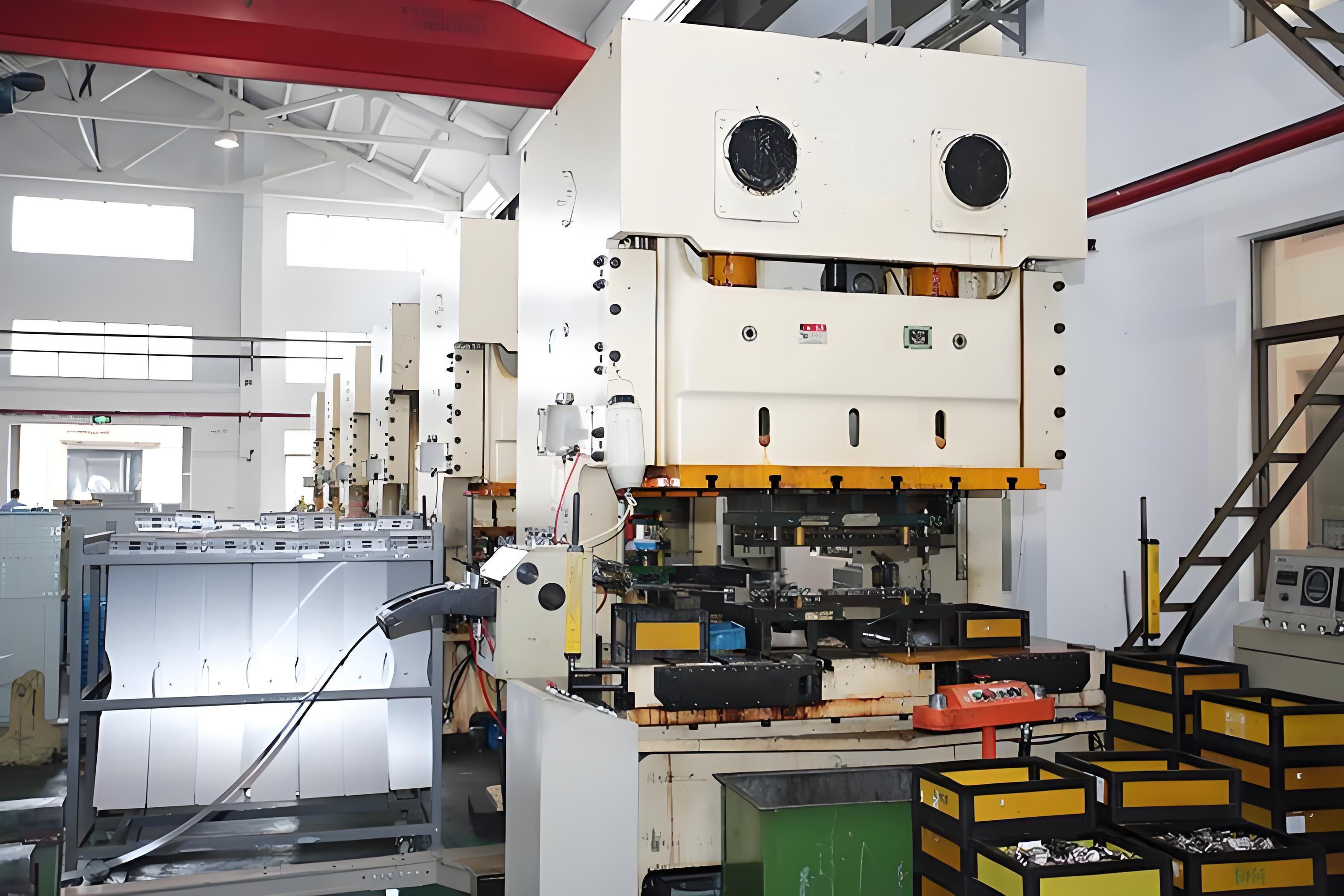
Ever picked up a metal can, a sensor housing, or a sleek appliance shell and wondered how it was made? Chances are, you’ve held a product of deep draw metal stamping in your hands. This process transforms flat sheet metal into seamless, three-dimensional shapes—think cylinders, boxes, or intricate cup-like forms—using a combination of dies and presses. Unlike standard stamping, which simply cuts or bends metal, deep drawing stretches the material into a new shape, making it ideal for parts that need strength, airtightness, and a flawless finish.
Drawing versus stamping explained
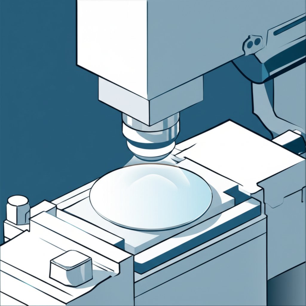
Sounds complex? Let’s break it down. Traditional metal stamping is all about cutting and simple forming—imagine punching out shapes from dough. Deep drawing, on the other hand, is like gently stretching that dough over a mold to create a deep cup without tearing it. In deep draw metal stamping, the sheet metal (called a blank) is drawn into a die cavity using a punch, gradually forming the desired geometry. This method is especially valuable for parts where a seamless wall is essential, such as:
- Automotive housings and fuel system shells
- Appliance cans and enclosures
- Instrument or electronics cases
- Medical device bodies
These metal stamped parts often feature straight sides, radii, and uniform wall thicknesses, which are difficult to achieve with standard stamping or machining. Deep draw is the go-to process for high-volume production of such components, delivering cost savings and repeatable quality.
Glossary essentials for new engineers
- Blanking: Cutting flat sheet metal into a pre-sized disc or shape before forming.
- Drawing: Stretching the blank into a die to create a cup or shell, the core of deep draw metal stamping.
- Redrawing: Further drawing an already formed part to increase depth or refine shape.
- Trimming: Removing excess material from the formed part’s edge for a clean finish.
Drawing transforms a flat blank into a seamless 3D shell without thinning beyond material limits when properly controlled.
Why choose deep draw for your application?
If your design calls for a part with significant depth, smooth walls, and minimal seams—think battery sleeves, pump housings, or sensor enclosures—deep drawing is often the best fit. The process delivers:
- Seamless strength—no welds, joints, or weak points
- Cost efficiency at scale—especially for high-volume runs
- Excellent repeatability—tight tolerances and consistent results
- Superior surface integrity—smooth finishes, fewer defects
However, deep draw metal stamping isn’t perfect for every situation. It’s less suitable for parts with very sharp corners, extremely deep draws without intermediate steps (redraws), or designs with drastic changes in cross-section. In those cases, alternative forming or machining methods may be needed [reference].
By understanding the basics of deep drawing and how it differs from other metal drawing operations, you’ll be better equipped to select the right process for your next project—and set realistic expectations for cost, quality, and lead time.
Step-by-Step Workflow for Deep Drawing Operations
Single-Draw Workflow from Blank to Shell
When you’re starting with a flat sheet and need a seamless, cup-shaped part, the deep drawing process follows a series of precise steps. Imagine you’re making a metal cup—each step ensures strength and a smooth finish. Here’s how the deep drawing operation typically unfolds:
- Blank Preparation: Cut a disc or preform (the blank) from sheet metal, sized to match the final part’s surface area. Cleanliness is critical—any debris or oil can cause surface defects later.
- Lubrication: Apply the appropriate lubricant to both sides of the blank. This step reduces friction, helps control metal flow, and prevents scoring during the process of deep drawing.
- Positioning in Die: Place the blank over the die cavity. A blankholder applies controlled pressure to hold the blank flat and prevent wrinkling.
- Drawing: The punch descends, pushing the blank into the die cavity. The metal flows inward, forming the cup shape with minimal stretching when properly controlled [source].
- Trimming: After drawing, excess material at the rim is trimmed away for a clean edge.
- Piercing/Secondary Operations: If holes or slots are needed, piercing or notching is performed at this stage.
- Inspection: The finished part is checked for dimensions, surface quality, and any defects.
When and Why to Use Redraws
Sometimes, a single draw isn’t enough—especially for tall or narrow parts. Here’s where multiple draws, or redraws, come in. Each redraw further reduces diameter and increases height, allowing for deeper shells without risking splits or excessive thinning. Decision points for redraws often depend on the height-to-diameter ratio and the material’s formability. If the part is too deep for one draw, the process is paused, the part is annealed if necessary (to restore ductility), and then drawn again. This stepwise approach is a hallmark of the deep drawing manufacturing process.
- First Draw: Form the basic cup shape from the blank.
- Intermediate Annealing (if needed): Heat treat the part to soften the metal before further drawing, especially for work-hardened materials.
- Redraw: Place the partially formed part in a new die and repeat the drawing in manufacturing process to achieve the final depth.
- Repeat as needed: Some parts require multiple redraws, each time with new dies and careful control of lubrication and blankholder force.
Documenting your lubrication and cleanliness strategy during each stage is vital, as it greatly reduces the risk of surface defects and ensures consistent results.
Progressive Dies Versus Transfer Setups
Choosing the right die setup is crucial for efficiency and part quality. Here’s how the two main approaches differ:
- Progressive Die Process: The metal strip moves continuously through a series of stations, each performing a specific operation (drawing, piercing, trimming) in rapid succession. This is ideal for high-volume, simpler parts where speed and repeatability are key.
- Transfer Die Process: Individual blanks are mechanically transferred from one station to the next. Each station can perform more complex operations, including multiple draws and intricate forming. Transfer dies excel for complex shapes, deep draws, or when precise control over each stage is required.
-
Progressive Approach:
- Feed coil strip into die
- Blanking, drawing, trimming, and piercing occur in sequence as the strip moves through the tool
- Parts are separated at the final station
-
Transfer Approach:
- Start with individual blanks
- Blank is drawn, then transferred to subsequent stations for redraws, piercing, or forming
- Greater flexibility for complex, deep draw process requirements
| Process Stage | Purpose | Typical Risks | Suggested Controls |
|---|---|---|---|
| Blank Preparation | Ensures correct material and size | Surface defects, wrong size | Clean, deburred blanks; check diameter |
| Lubrication | Reduces friction, controls flow | Scoring, tearing | Use recommended lubricants; maintain cleanliness |
| Drawing | Forms initial cup/shell | Splitting, wrinkling | Optimize punch/die radii; adjust blankholder force |
| Redraw/Anneal | Achieves final depth/shape | Work hardening, cracks | Anneal as needed; control reduction per draw |
| Trimming/Piercing | Removes excess material, creates holes | Burrs, distortion | Sharp tooling, proper alignment |
| Inspection | Verifies quality and dimensions | Missed defects | Use calibrated gauges; document results |
Throughout every stage, keep in mind that real-world parameters—like press tonnage, draw bead design, and blankholder forces—must be tailored to your material, part geometry, and supplier’s equipment. Always refer to supplier data or trusted handbooks for guidance, and validate your process through trials. By mastering the fundamentals of the deep draw process, you’ll be well prepared for the next step: designing robust tooling and dies that minimize risk and maximize part quality.
Tooling and Die Design
Die Components That Control Metal Flow
Ever wonder why some deep drawn parts come out flawless while others wrinkle or tear? The answer often lies in the details of the tooling—specifically, the draw die and its components. Imagine the draw die as the heart of deep draw metal stamping: it shapes, guides, and controls every move the metal makes. Let’s break down the essential parts:
| Die Component | Function | Typical Wear Modes | Maintenance Notes |
|---|---|---|---|
| Punch | Pushes the blank into the die cavity, shaping the part | Scoring, galling, chipping | Inspect for wear and polish regularly |
| Die Cavity | Receives the blank, defines the outer shape | Surface wear, pitting | Monitor for surface defects, maintain smooth finish |
| Blankholder/Pressure Ring | Applies pressure to control metal flow, prevents wrinkling | Indentation, uneven wear | Check pressure uniformity and surface integrity |
| Draw Beads | Regulate material flow into the die cavity | Wear at bead peaks, galling | Polish and inspect for buildup |
| Radii (Punch/Die) | Guide metal flow, reduce stress concentrations | Chipping, scoring | Maintain generous, smooth radii; avoid sharp corners |
| Clearances | Allow for material thickness and flow | Excessive wear if too tight, wrinkling if too loose | Review during setup and after long runs |
Each part of the drawing die must be engineered with the specific material and geometry in mind. For example, a small punch radius can cause tearing, while a too-large clearance may lead to wrinkling. That’s why collaboration between design, tooling, and manufacturing teams is crucial for success.
Blankholder Design and Force Selection
Picture this: you’re pressing dough into a pie pan. Too little pressure and the dough wrinkles; too much, and it tears. The blankholder in a draw die works the same way. Its job is to clamp the sheet’s edge, controlling how much metal feeds into the cavity. The right blankholder force is a balancing act:
- Too low: Material wrinkles as it flows too quickly.
- Too high: Metal can’t move, risking splits and excessive thinning.
Adjusting blankholder pressure, along with strategic placement of draw beads, helps fine-tune the metal flow. For complex parts, simulation and prototyping are often used to test and refine these settings before full-scale production. This careful approach helps avoid costly defects and keeps your deep drawing operation running smoothly.
Tooling Materials and Surface Treatments
The durability and quality of a deep drawing die depend heavily on the materials and coatings selected. Common choices include:
- Tool Steels: Widely used for punches and die cavities due to their hardness and toughness.
- Carbides: Offer excellent wear resistance for high-volume or abrasive applications.
- Low-Alloy Steels: Sometimes used for less demanding tooling, often enhanced by heat treatments.
Surface treatments and coatings can further boost tool life and performance. Here’s a quick guide to common options and their benefits:
- Chromium Plating: Improves wear resistance and reduces galling.
- Nitriding: Hardens the tool surface for better durability.
- Physical Vapor Deposition (PVD) Coatings: Adds lubricity and wear resistance, especially for demanding materials.
- Carburizing/Carbonitriding: Surface hardening for low-alloy steels, enhancing toughness and longevity.
Choosing the right combination of base material and coating is a key factor in minimizing downtime and ensuring consistent part quality [reference].
Progressive versus Transfer Die Selection
How do you pick between a progressive die and a transfer die for your next project? It comes down to part complexity, production volume, and flexibility needs:
- Progressive Dies: Best for high-volume runs of smaller, less complex parts. The strip advances through multiple stations in one tool, each performing a specific operation like piercing or drawing. This setup is highly efficient for parts that don’t require repositioning or complex forming at each stage.
- Transfer Dies: Ideal for larger, deeper, or more intricate parts that need multiple forming steps. Parts are moved from station to station, allowing for more flexibility and the ability to integrate secondary operations. Transfer dies are also preferred for lower-volume production or when part design may change over time.
Consider this: if you’re making millions of identical, simple cups, a progressive die is often the go-to. But if your part has varying depths, side features, or requires secondary forming, a transfer die provides the adaptability you need.
Maintenance and Inspection: The Key to Long Tool Life
You’ll notice that even the best-designed sheet metal punch and die assemblies will wear over time. Regular inspection and scheduled polishing are critical for preventing surface defects like scoring and galling. Record wear patterns and feedback from production to refine future tool builds and maintenance schedules. This proactive approach not only extends tool life but also reduces unexpected downtime and scrap rates.
By understanding the core elements of draw die design, material selection, and maintenance, you can dramatically reduce risk in deep draw metal stamping. Next, we’ll explore how material choices and formability directly impact your ability to achieve high-quality, defect-free draws.
Materials and Formability
Material Selection Matrix for Drawn Parts
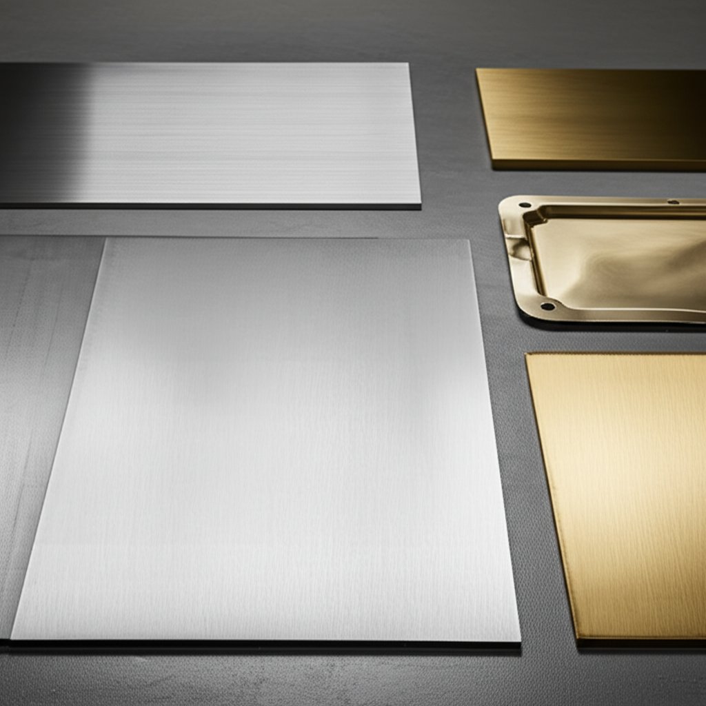
When you’re planning a deep draw metal stamping project, one of the first questions to ask is: “What metal should I use?” The answer shapes everything—formability, strength, surface finish, cost, and even the number of redraws or annealing steps you’ll need. Imagine two parts: one is a food-grade can that must resist corrosion, the other is a structural bracket that needs strength above all else. The ideal material for each is different, and so is the approach to deep drawing steel sheet, aluminum, brass, or stainless steel.
| Material | Formability | Surface Finish Potential | Corrosion Resistance | Typical Use Cases |
|---|---|---|---|---|
| Low Carbon Steel (Drawing/Deep Drawing Grades) |
Excellent (high ductility, low springback) | Good, can be further improved with coatings | Low (needs coating/painting) | Automotive panels, appliance housings |
| Stainless Steel (304, 316, 409, AM350, Alloy 20) |
Moderate (requires higher force, work-hardens quickly) | Very good (clean, bright finish) |
Excellent | Medical devices, food containers, marine parts |
| Aluminum Alloys | Very good (low force, easy to form) | Good (prone to surface marks) | Very good | Lightweight enclosures, automotive trim, electronics |
| Brass (Cartridge, 70/30) | Excellent (high ductility, smooth flow) | Excellent (golden finish) |
Good | Decorative parts, electrical fittings |
| High Strength/Advanced Steels | Lower (requires careful control, higher force) | Good (may need post-finishing) | Varies (often needs coating) | Chassis, crash components, structural brackets |
Formability Cues and LDR Concepts
Sounds technical? Let’s break it down. The best metals for deep drawing combine ductility (the ability to stretch without cracking) and controlled work hardening (how much stronger the metal gets as it’s formed). For deep drawing of steel, low carbon grades with fine grain structure are popular because they stretch easily and don’t spring back much. Stainless steel, while tougher and more corrosion-resistant, work-hardens more quickly and needs more force. That means you might need multiple draws or intermediate annealing to avoid splits or tears [reference].
The limiting draw ratio (LDR) is a key concept—it’s the maximum ratio of blank diameter to punch diameter that can be drawn in one step without failure. Materials with higher ductility (like deep drawing steel sheet or deep drawn aluminum) can achieve higher LDRs, meaning deeper parts in fewer steps. If you push beyond the LDR, expect to add redraws or annealing cycles to restore ductility.
Don’t forget about earing—those wavy edges that appear on deep drawn cups. Earing is often a result of planar anisotropy in the sheet (the way grains are oriented). You’ll notice it more in textured or rolled sheets. To minimize earing, adjust the blank’s orientation or work with your supplier to select a material with a balanced grain structure. Process tuning can also help reduce this effect, saving time and scrap.
Datasheet formability and supplier trials should jointly drive final choices. A material that looks good on paper may behave differently in your specific deep draw setup—always validate with real-world tests.
Surface Finish and Downstream Finishing
Surface finish expectations are critical, especially if your part will be visible or require further processing. Stainless steel deep draw parts often emerge with a bright, clean finish, making them ideal for food, medical, or decorative uses. Aluminum is also valued for its corrosion resistance and light weight, but can show tool marks more easily—take extra care with lubrication and die condition. Brass offers a smooth, gold-toned finish straight from the press, reducing the need for secondary polishing in many decorative applications.
Keep in mind that some materials—like deep drawing steel sheet—may require post-forming plating or painting for corrosion protection. Stainless stamping, in contrast, can often skip this step, though costs and forming force are higher. When planning for downstream operations like piercing, plating, or deburring, consider how your material choice will impact each stage. For example, harder materials may increase tool wear during piercing, while softer ones may require more careful handling to prevent surface damage.
When to Anneal and When to Redraw
Annealing (softening the metal by controlled heating) is sometimes needed between draws, especially with stainless steel deep draw or high-strength alloys that work-harden rapidly. If your part cracks or shows excessive thinning after a draw, an intermediate anneal can restore ductility and allow further forming. For many low carbon steels, redraws can be performed without annealing, but always monitor for signs of work hardening or loss of formability [reference].
Ultimately, choosing the right material for deep drawing metal is about balancing formability, strength, finish, and cost—while keeping an eye on how each property affects the process and the final product. Next, we’ll look at how these material decisions influence achievable tolerances, surface quality, and repeatability in your stamped parts.
Tolerances, Surface Finish, and Repeatability in Deep Drawn Components
Specifying Tolerances Without Over-Constraining
When you’re designing deep drawn components, how tight should your tolerances be? Sounds simple, but the answer depends on more than just a number on a drawing. Achievable tolerances in deep draw metal stamping are shaped by your shop’s equipment, the quality of the tooling, lubrication consistency, and inspection methods. For example, a state-of-the-art press with advanced die alignment and real-time process controls can hold tighter tolerances than a basic manual setup.
Instead of defaulting to the tightest possible numbers, focus on what’s truly critical to your part’s function. Over-constraining tolerances increases cost and scrap risk—especially in deep drawing, where material flow and tool wear can introduce subtle variations. Early in the design phase, identify your part’s must-have features, such as sealing surfaces or press-fit diameters. Then, work with your supplier to align on datum schemes and inspection plans that target these features.
| Process Option | Tolerance Tightness | Surface Finish Potential | Repeatability Considerations |
|---|---|---|---|
| Single Draw | Moderate (varies by material and depth) | Good, minor tool marks possible | High with stable tooling and controls |
| Redraw with Anneal | Improved (restores ductility, reduces springback) | Very good, especially after restrike | High, but depends on anneal consistency |
| Progressive with Restrike | Tightest, especially for holes and flanges | Excellent, can approach machined quality | Very high, best for large runs |
| Post-Draw Machining | Precision (down to machining limits) | Best, as surface is cut or ground | Extremely high, but adds cost |
Surface Finish and Burr Control
Ever wondered why some stamped parts look flawless, while others need extra work? The answer often lies in surface finish and burr control. Deep drawing typically produces smooth, uniform surfaces—especially when the die and punch are well-maintained and lubrication is properly managed. However, secondary operations like trimming, piercing in sheet metal, or using a hole puncher for metal can introduce burrs or sharp edges.
To minimize these issues, consider integrating post-draw processes such as restrike (a light re-forming step to sharpen features), sizing, or precision piercing. For critical holes, a dedicated sheetmetal hole punch or even a post-forming machining step may be needed to achieve the best results. Finishing operations like shaving or deburring can further improve edge quality and dimensional accuracy.
- Specify radiused or chamfered edges on prints to avoid sharp burrs.
- Call out lubrication cleanliness to prevent scoring or galling.
- Include inspection notes for critical features—especially those formed by piercing in sheet metal.
Repeatability and Gage Strategy
Imagine producing thousands of deep drawn components—will the last one be as good as the first? Repeatability hinges on robust tooling, controlled process parameters, and a solid inspection plan. Advanced manufacturers use metrology tools like coordinate measuring machines (CMM) or laser scanners to check dimensions and surface finish. For features created by a hole puncher for metal, dedicated go/no-go gauges or custom fixtures can ensure every part meets spec.
To make inspection efficient and reliable, define datums and gage points clearly on your drawings. Collaborate with your supplier early to design metrology fixtures that match your part’s geometry and critical-to-quality features. This not only speeds up inspection but also reduces the risk of ambiguous or inconsistent measurements.
By setting realistic tolerances, specifying surface finish requirements, and planning for repeatable inspection, you’ll set your deep draw project up for success. Up next, we’ll explore how to troubleshoot common defects—and how process tweaks can keep your production line running smoothly.
Troubleshooting Defects
Wrinkling Causes and Fixes
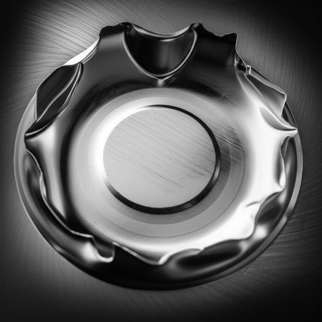
Ever notice wavy edges or ripples on deep drawn parts? Wrinkling is one of the most common issues in deep drawing sheet metal forming, and it can be frustrating. Imagine forming a metal cup—if the edge looks like a ruffled collar, you’re seeing classic wrinkling. Here’s how to break down the problem and get back on track:
- Symptoms: Wavy, uneven flanges or sidewalls, especially near the rim.
-
Root Causes:
- Blankholder force too low—material flows too freely.
- Poor bead design—insufficient resistance to metal flow.
- Die or punch radii too large—reduces control over draw-in.
- Excessive lubrication—reduces friction needed for controlled flow.
-
Corrective Actions:
- Increase blankholder pressure to restrain the blank.
- Refine bead geometry for more consistent draw-in.
- Reduce die and punch radii if excessive.
- Optimize lubrication—enough to prevent scoring, but not so much that control is lost.
Addressing wrinkling early keeps your deep draw forming process efficient and your parts looking professional. Regular inspection and process documentation help catch these issues before they impact downstream operations.
Tearing and Thinning Prevention
When you see splits or cracks in your deep drawing sheet metal, it’s a sign the material has been overstressed. Tearing often occurs at the bottom radius or sidewall, especially with aggressive draws or improper tooling. Here’s how to diagnose and fix it:
- Symptoms: Visible cracks, splits, or excessive thinning at the cup bottom or corners.
-
Root Causes:
- Punch/die clearance too tight—material can’t flow smoothly.
- Sharp radii—high stress concentrations.
- Insufficient lubrication—excessive friction and heat.
- Draw depth too great for a single operation.
- Work-hardened material from previous operations.
-
Corrective Actions:
- Increase punch and die radii to reduce stress.
- Check and adjust punch/die clearance for your material thickness.
- Apply or improve lubrication to reduce friction.
- Split the operation into multiple draws (add a redraw step).
- Anneal the part between draws to restore ductility if needed.
For metal deep drawing, preventing tears is about balancing force, geometry, and material properties. If you’re consistently seeing thinning, review your process flow and consider intermediate annealing or adjusting your draw sequence.
Earing Mitigation and Springback Control
Have you ever noticed wavy, ear-like protrusions around the rim of a drawn part? That’s earing, a defect linked to the grain direction of your sheet metal. Springback, on the other hand, is when the part doesn’t hold its shape after forming—making precise dimensions a challenge. Here’s how to manage both:
- Symptoms: Wavy, uneven rim heights (earing); parts that change shape after release (springback).
-
Root Causes:
- Sheet anisotropy—material grains not aligned for uniform flow.
- Improper blank orientation—maximizes grain effects.
- Insufficient restrike or sizing operations—part relaxes after forming.
-
Corrective Actions:
- Rotate or reorient the blank relative to the grain direction.
- Select sheet materials with balanced grain structure for deep draw forming.
- Add a restrike or sizing operation to lock in shape and dimensions.
- Collaborate with your supplier to minimize anisotropy at the sourcing stage.
Managing earing and springback is essential for consistent draw depth and reliable downstream assembly. These adjustments are especially critical in high-precision deep drawing sheet metal forming.
Surface Scoring, Scratches, and Other Quality Issues
Surface defects like scratches, scoring, or galling can compromise both the function and appearance of metal deep drawing parts. These issues often stem from tool wear, poor lubrication, or contamination:
- Symptoms: Visible lines, grooves, or rough patches on the part surface.
-
Root Causes:
- Worn or damaged die and punch surfaces.
- Insufficient or contaminated lubrication.
- Dirty blanks or tooling—foreign particles dragged across the surface.
-
Corrective Actions:
- Regularly polish and inspect dies and punches.
- Use clean, high-quality lubricants and maintain a clean work environment.
- Implement strict cleaning protocols for blanks before drawing.
By focusing on tool maintenance and cleanliness, you can dramatically improve the surface quality of your deep draw forming products.
Quick Reference: Defect-to-Fix Table
| Defect | Key Process Levers | Suggested Fix |
|---|---|---|
| Wrinkling | Blankholder force, bead design, radii, lubrication | Increase blankholder, refine beads, reduce radii, optimize lube |
| Tearing/Thinning | Punch/die clearance, radii, lubrication, draw sequence, annealing | Increase radii, adjust clearance, improve lube, add redraw/anneal |
| Earing | Blank orientation, material selection, restrike | Rotate blank, source balanced sheet, add restrike |
| Springback | Restrike, sizing, material selection | Add restrike/sizing, choose material with low springback |
| Surface Scoring | Tool condition, lubrication, cleanliness | Polish tools, use clean lube, clean blanks/tools |
By using this practical playbook and understanding how each lever—like radii, blankholder force, or draw sequence—affects your results, your team can act quickly when challenges arise in metal deep drawing. Proactive troubleshooting not only improves part quality but also reduces scrap and downtime. As you master these fixes, you’ll be ready to optimize cost and supplier selection, the focus of our next section.
Cost Drivers and Procurement Playbook for Deep Draw Metal Stamping
Tooling Versus Piece-Price Tradeoffs
When you’re sourcing deep draw metal stamping, understanding the balance between upfront tooling costs and per-part pricing is crucial. Imagine you’re launching a new product: should you invest heavily in tooling for long-term savings, or keep initial costs low for flexibility? Here’s how it breaks down:
- Tooling Complexity: More complex part geometries—like those with rolled threads, side piercings, or embossing—require more intricate dies, increasing both design and build costs. High-complexity tools also take longer to develop and may need additional maintenance over the life of the project.
- Material Choice: Harder or specialty materials (such as advanced high-strength steels) can drive up tool wear and require premium tool steels or carbides, raising both initial and ongoing costs.
- Part Geometry and Size: Deeper draws or larger parts often mean more forming steps, bigger presses, and more robust tooling—impacting both cost and lead time.
- Volume: High-volume runs can amortize tooling costs across thousands or millions of parts, lowering the piece price. For low-volume or prototype work, simpler, less durable tooling may be more cost-effective, but expect higher per-part costs.
In deep draw manufacturing, the right strategy depends on your priorities. If you’re producing millions of parts, investing in high-quality, long-life tooling pays off. For pilot runs or frequent design changes, opt for flexible tooling and processes to minimize sunk costs.
RFQ Package Checklist for Reliable Quotes
Ever received a quote that didn’t match your expectations? That’s often due to incomplete or unclear RFQ (Request for Quotation) packages. To get accurate, competitive pricing for stamping services, your RFQ should cover every critical detail. Here’s a practical checklist:
- 2D and 3D CAD files with full dimensions and tolerances
- Material specification and acceptable alternates (e.g., type of sheet metal for stamping, thickness range)
- Target annual and batch volumes
- Required surface finish and cosmetic zones
- Critical features and tolerances (highlighted on drawings)
- Planned secondary operations (trimming, piercing, plating, deburring, etc.)
- Inspection and quality requirements (e.g., CMM, SPC, PPAP level)
- Packing, labeling, and delivery preferences
- Openness to DFM feedback or suggested alternates
Including this information up front helps deep draw metal stamping manufacturers provide precise, realistic quotes—minimizing surprises and excessive contingency fees.
Supplier Capability and Press Selection
Choosing the right partner goes beyond price. Imagine your supplier’s shop floor: do they have the right press range, automation, and quality systems to support your project? Here’s what to evaluate:
- Press Range: Do they offer presses sized for your part’s depth and diameter? This is especially important for deep draw manufacturing, where draw depth and tonnage requirements vary widely.
- Die Strategies: Are they equipped for both progressive and transfer die setups? Progressive dies excel at high-volume, repeatable parts, while transfer dies offer flexibility for complex or deep-drawn shapes.
- Automation and In-Die Sensing: Advanced automation reduces labor cost and improves consistency. In-die sensors help catch defects early, supporting high-quality sheet metal stamping services.
- Quality Certifications: Look for ISO or industry-specific certifications as a baseline for process control and traceability.
- Multi-Sourcing and Risk: For critical components, consider qualifying multiple suppliers to de-risk your supply chain.
| Volume Band | Common Die Strategy | Changeover Considerations |
|---|---|---|
| Prototype/Low Volume | Single-stage or soft tooling | Quick change, high flexibility |
| Medium Volume | Transfer dies | Moderate changeover, adaptable for design tweaks |
| High Volume | Progressive dies | Longer setup, optimized for repeatability and speed |
When requesting quotes, encourage suppliers to suggest process or material alternates—sometimes a minor change in the type of sheet metal for stamping or die setup can save significant cost or lead time. An open, collaborative approach to deep draw manufacturing sets the stage for a successful partnership.
Armed with a clear understanding of cost drivers, RFQ best practices, and supplier evaluation criteria, you’ll be ready to plan your next project with confidence. In the next section, we’ll dive into engineering calculations and planning methods to further de-risk your deep draw initiatives.
Calculations and Planning Methods to De-Risk Deep Draw Metal Forming
Tonnage and Energy Considerations
Ever wondered how engineers decide which deep drawing press or draw press is right for your project? It starts with understanding the force, or tonnage, required for each stage of deep draw metal forming. Tonnage is the maximum force the press must exert to shape the blank without causing defects. If you underestimate, you risk tool damage or incomplete forming; overestimate, and you may overspend on equipment. Factors like material strength, blank thickness, part geometry, and reduction per draw all influence the tonnage needed. For instance, harder materials and deeper draws call for higher-capacity deep drawing presses—sometimes specialized units like a tiefziehpresse (deep drawing press in German) for especially demanding applications. Always consult supplier data or trusted engineering handbooks for guidance, and remember: real-world validation is key.
Early parameter estimation—whether for tonnage, blank size, or blankholder force—should always be validated with tryout data and close supplier feedback before committing to production.
Blank Sizing and Nesting Strategy
Imagine you’re planning to make a cylindrical cup. How big should your starting blank be? The answer lies in balancing material efficiency with enough stock to form the part without thinning or tearing. The blank’s diameter is typically calculated so its surface area matches the final part’s area (including any flange or trim allowance). For example, a deep drawn cup’s blank size must account for wall height, base, and any extra for trimming. Reference charts or simulation tools—often provided by deep draw presses suppliers—can help refine these estimates. Nesting (how you arrange blanks on a sheet) also impacts scrap rates and cost, so early planning pays off.
| Planning Task | Key Inputs | Expected Output |
|---|---|---|
| Tonnage Estimation | Material properties, thickness, part geometry, reduction ratio | Press size (tonnage range), energy required |
| Blank Sizing | Finished part dimensions, wall height, trim allowance | Blank diameter, nesting plan |
| Blankholder Force Planning | Material ductility, draw depth, flange width, friction/lubrication | Blankholder force range, bead design guidelines |
| Draw Sequence/LDR Planning | Limiting draw ratio (LDR), material work hardening, part aspect ratio | Number of draws, need for annealing or redraws |
Blankholder Force and Draw Bead Planning
Think of the blankholder as the gatekeeper of your deep draw. Too little force and the blank wrinkles; too much and it tears. The right balance depends on material ductility, lubrication, and part geometry. For complex shapes or high-aspect-ratio parts, draw beads (raised features in the die) help regulate metal flow, preventing defects. It’s common to start with conservative force estimates, then fine-tune during trials or simulations. Modern deep drawing presses and tiefziehpresse systems often allow programmable blankholder force profiles for even greater control, especially in advanced deep draw metal forming scenarios.
Simulations and controlled tryouts are invaluable for refining these parameters. By collaborating with your tooling supplier, you can use digital models to predict risks, optimize draw steps, and minimize costly surprises. If in doubt, err on the side of caution—allow for extra blank size, use a slightly larger press, and plan for at least one redraw if pushing the limits of your material’s LDR (Limiting Draw Ratio).
By approaching calculations and planning with a conservative, data-driven mindset—and validating every estimate through tryouts—you’ll set your deep draw project up for smooth production and fewer headaches. Next, we’ll see how a DFM-focused supplier can help accelerate your launch and scale with confidence.

How DFM and Scalable Production Accelerate Deep Draw Stamping Launches
How DFM-Focused Vendors De-Risk Deep Draw Launches
When you’re launching a new automotive component, the stakes are high: tight deadlines, rigorous quality expectations, and the need for cost control from prototype to mass production. You might wonder—how do successful teams avoid costly rework and late-stage surprises in deep draw stamping? The answer often lies in early, collaborative Design for Manufacturability (DFM) reviews and partnering with suppliers who are equipped for both flexibility and scale.
DFM isn’t just a buzzword. It’s a structured approach where your supplier’s engineers work hand-in-hand with your design team to identify risks, propose optimizations, and validate that your deep drawn metal part can be produced reliably—before you commit to expensive tooling. For example, a DFM review might reveal opportunities to adjust radii, material selection, or feature locations, saving weeks of rework and thousands in tooling modifications later on.
- Early DFM reviews highlight risks and cost drivers before tooling is cut.
- Prototype iterations allow for real-world validation and rapid design tweaks.
- Automated quality checks and in-die sensing catch defects early, supporting consistent deep drawn metal quality.
What to Evaluate in an Automotive Deep Draw Partner
Not all suppliers are created equal—especially when it comes to deep drawn metal for automotive use. Imagine you’re evaluating potential partners: beyond price, what should you look for?
- Material Breadth: Can they process high-strength steel, stainless, and aluminum alloys to match your application’s needs?
- Tooling and Press Range: Do they have the in-house capability to design, build, and maintain tooling for both small and complex parts?
- Quality Systems: Look for certifications (like ISO 9001 or IATF 16949) and robust quality control protocols.
- Flexibility: Are they equipped to scale from low-volume prototyping to high-volume production without missing a beat?
- Experience: Do they have a proven track record with deep drawn metal stampings in demanding automotive environments?
"Certification and cross-industry experience signal that a supplier can consistently deliver deep drawn metal parts that meet stringent automotive standards."
For instance, Shaoyi Metal Technology exemplifies these traits by offering IATF 16949 certified production, DFM-driven engineering, and the ability to handle both rapid prototyping and mass production for deep drawn metal automotive components.
Prototyping to Mass Production: Scaling Considerations
Scaling from a handful of prototypes to full-scale automotive production introduces new challenges. Will your supplier’s process controls hold up under volume? Can they maintain consistent tolerances and surface quality across thousands—or millions—of deep drawn metal parts?
- Prototype Feedback Loop: Fast iterations enable you to validate design changes and process tweaks before scaling up.
- Press and Automation Options: A supplier with a range of presses (from small transfer presses to high-tonnage progressive lines) can match your project’s evolving needs.
- Integrated Quality Assurance: Automated inspection, SPC (statistical process control), and traceability systems help ensure every deep drawn metal part meets spec.
- Responsive Engineering Support: Direct access to tooling and process engineers accelerates troubleshooting and continuous improvement.
Case studies from industry leaders show that teams who engage their deep draw stamping partner early—leveraging DFM, simulation, and prototype validation—consistently launch faster and with fewer surprises. This is especially true for deep drawn metal parts with complex geometries or stringent performance requirements.
In summary, choosing a partner with robust DFM expertise, broad material and press capabilities, and proven quality systems is key to de-risking your deep draw stamping launch. As you move from design through prototyping and into mass production, these attributes ensure your deep drawn metal components meet cost, quality, and delivery targets. Next, we’ll wrap up with actionable next steps and trusted resources for ongoing success in deep draw metal stamping.
Conclusion
Actionable Next Steps for Your Deep Drawing Projects
When you’re ready to put deep draw metal stamping into practice, the path to success is all about alignment and continuous improvement. Imagine you’ve just finished reading about the process, materials, and troubleshooting—what comes next? Here’s a practical checklist to help you move forward confidently, whether you’re designing your first emboutissage project or scaling up to high-volume production:
- Align design targets early: Collaborate with engineering, quality, and procurement teams to define critical features, tolerances, and cosmetic requirements before tool build begins.
- Validate assumptions with trials: Use prototype runs or supplier tryouts to confirm that your deep drawing process for complex metal forming matches your expectations for part quality and manufacturability.
- Maintain a feedback loop: Implement robust PPAP (Production Part Approval Process) and ongoing production monitoring to catch issues early and drive continuous improvement.
- Document process learnings: Record findings from each emboutissage trial—what worked, what needed adjustment, and how defects were resolved. This knowledge will streamline future projects.
- Consult with certified partners: For automotive and high-reliability applications, consider working with an IATF 16949 certified deep draw supplier. Their DFM insight and scalable production resources can help you avoid costly missteps. For example, Shaoyi Metal Technology offers DFM reviews and a full range of press and automation options to support your emboutissage needs from prototype to mass production.
Trusted References and Standards for Deep Drawing Manufacturing
Looking to deepen your expertise or back up your decisions with authoritative data? Here are some proven resources that engineers, buyers, and quality professionals rely on for deep drawing manufacturing and emboutissage:
- ASM Handbook, Volume 14B: Sheet Metal Forming – This is one of the most comprehensive technical references on sheet metal forming, including deep drawing.
- ISO 20482:2013 – International standard for sheet metal formability testing (Erichsen cupping test), foundational for understanding what is deep drawing and material performance. [ISO Standard]
- SME (Society of Manufacturing Engineers) – Offers best practices, case studies, and training on deep drawing process for complex metal forming and related technologies.
- Peer-reviewed journals: Publications like the Journal of Materials Processing Technology and CIRP Annals regularly feature advances in tiefziehen, dieptrekken, and deep draw process optimization.
- Supplier technical libraries: Many reputable deep draw metal stamping manufacturers provide application notes, design guides, and calculators to help you plan and validate your process.
Align Design, Tooling, and Process Early
"The most successful emboutissage projects start with early alignment between design, tooling, and process teams—ensuring that manufacturability, cost, and quality targets are met from concept to full-scale production."
As you move from concept to launch, remember: deep drawing manufacturing is a team sport. Early and open collaboration—supported by trusted standards and real-world data—will help you avoid surprises, minimize rework, and deliver high-quality stamped parts on time and on budget.
Still have questions about what is deep drawing, process validation, or supplier selection? Don’t hesitate to reach out to a certified partner or explore the references above for deeper insights. With the right foundation, your next emboutissage project is set for success.
Frequently Asked Questions about Deep Draw Metal Stamping
1. What is deep draw metal stamping and how does it differ from regular stamping?
Deep draw metal stamping is a process that forms flat sheet metal into seamless, three-dimensional shapes using dies and presses. Unlike regular stamping, which primarily cuts or bends metal, deep drawing stretches the material into deeper forms like cylinders or boxes. This method is ideal for producing strong, airtight, and smooth-walled parts that require high repeatability and surface quality.
2. What types of parts are best suited for deep draw metal stamping?
Deep draw metal stamping is best for parts that require significant depth, seamless construction, and consistent wall thickness. Common applications include automotive housings, appliance cans, instrument enclosures, medical device bodies, and battery sleeves. The process excels when producing high volumes of cylindrical, box-shaped, or cup-like components.
3. What materials are commonly used in deep drawing and how do I choose the right one?
Materials often used in deep drawing include low carbon steel, stainless steel, aluminum alloys, and brass. The choice depends on the required formability, strength, corrosion resistance, and surface finish. For example, stainless steel offers excellent corrosion resistance and a clean finish, while low carbon steel is highly ductile and cost-effective. Always consider formability, work hardening, and downstream operations when selecting a material.
4. How can I prevent common defects like wrinkling or tearing in deep drawn parts?
Preventing defects in deep drawn parts involves optimizing blankholder force, tool radii, lubrication, and draw sequence. Wrinkling can be reduced by increasing blankholder pressure and refining bead design, while tearing is often addressed by increasing tool radii, adjusting clearances, and using intermediate annealing or redraws. Regular tool maintenance and clean working conditions also help minimize surface defects.
5. What should I include in an RFQ package for deep draw metal stamping services?
A comprehensive RFQ package should contain 2D and 3D CAD files, material specifications, annual and batch volume targets, surface finish and cosmetic requirements, critical tolerances, details on secondary operations, inspection requirements, and openness to DFM suggestions. Providing this information helps suppliers deliver accurate quotes and ensures your project is set up for success.