 Small batches, high standards. Our rapid prototyping service makes validation faster and easier —

Essential Strategies for Designing Machinable Die Cast Parts

TL;DR
Designing for machining in die cast parts is a critical engineering discipline that applies Design for Manufacturability (DFM) principles to optimize a component for both the initial casting process and any required secondary machining. Success hinges on balancing features that ensure smooth metal flow and easy part ejection—like draft angles, uniform wall thickness, and generous fillets—with accommodations for post-machining, such as adding sufficient material stock for tight tolerance features. This integrated approach is essential for reducing costs, minimizing defects, and creating a high-quality, economical final product.
Fundamentals of Design for Manufacturability (DFM) for Die Cast Parts
At the core of creating successful die cast components is the methodology of Design for Manufacturability (DFM). As explained in a beginner's guide from Dynacast, DFM is the practice of designing parts to be produced in the most efficient and cost-effective way possible. The primary goals are to reduce material volume, minimize weight, and, crucially, limit the need for secondary operations like machining, which can account for a significant portion of the total part cost. By addressing potential manufacturing issues early in the design stage, engineers can prevent expensive fixes down the line.
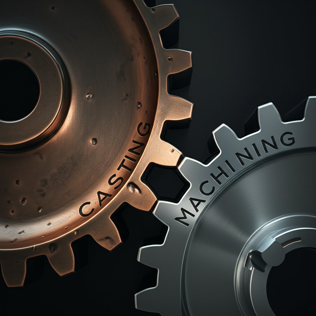
A key strategic decision in DFM is choosing between machining and casting, especially when considering a product's entire lifecycle from prototype to mass production. Machining is the champion for prototyping, offering speed and flexibility. A CAD file can become a physical part in days, allowing for rapid iteration without the substantial upfront investment in tooling. However, machining is expensive on a per-part basis. In contrast, casting is the powerhouse for production. While it requires a significant initial investment in tooling—often with lead times of 20-25 weeks—the per-unit cost plummets at high volumes, as highlighted in a strategic analysis by Modus Advanced.
This economic trade-off often leads to a "Two-Design Approach." A prototype design is optimized for CNC machining, allowing for sharp corners and variable wall thicknesses that facilitate quick testing. A separate production design is then created with casting-friendly features like draft angles and uniform walls. Understanding this distinction is vital for managing timelines and budgets effectively.
The table below illustrates the typical cost-per-part trade-offs between machining and casting at different production volumes, demonstrating the clear economic advantage of casting at scale.
| Volume Range | Machining Cost/Part (Estimate) | Casting Cost/Part (Estimate, with Amortized Tooling) | Economic Viability |
|---|---|---|---|
| 1-10 parts | $200 - $1000 | Not Applicable (Tooling cost is prohibitive) | Machining is the only practical option. |
| 100-1000 parts | $200 - $1000 | $50 - $150 | Casting becomes highly cost-effective. |
| 1000+ parts | $200 - $1000 | $10 - $50 | Casting offers significant savings. |
Core Die Casting Design Principles for Machinability
A successful die cast part that is also ready for machining relies on a set of fundamental design principles. These rules govern how molten metal flows into the die, cools, and is ejected, all while anticipating any necessary finishing touches. Mastering these concepts is essential for creating robust, high-quality components efficiently.
Parting Lines and Draft Angles
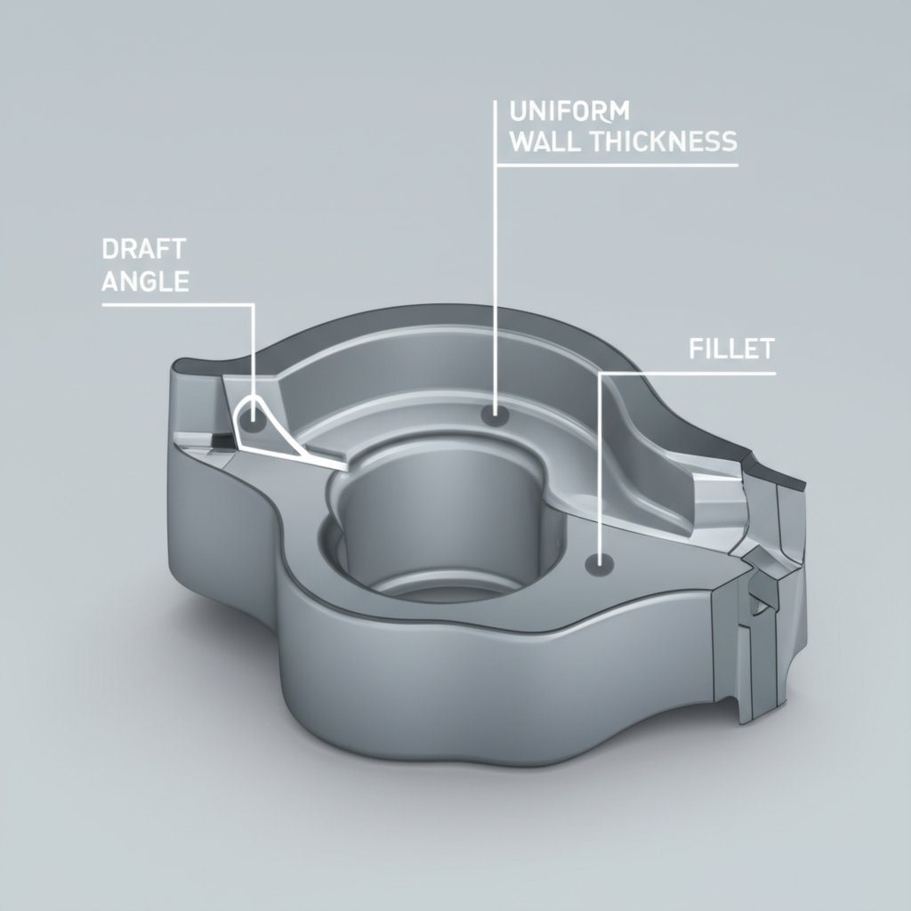
The parting line is where the two halves of the die meet. Its placement is one of the first and most critical decisions, as it affects the location of flash (excess material that must be trimmed) and the complexity of the tool. As a best practice, parting lines should be placed on edges that are easily accessible for trimming. A crucial related feature is the draft angle, which is a slight taper on all surfaces parallel to the die's movement. This taper, typically 1-2 degrees for aluminum, is essential for allowing the part to be ejected without being damaged or causing excessive wear on the tool, a point noted in a beginner's guide from Dynacast. Inner walls require more draft than outer walls because the metal shrinks onto them during cooling.
Uniform Wall Thickness
Maintaining a consistent wall thickness throughout the part is perhaps the most important rule in die casting design. Non-uniform walls cause uneven cooling, which leads to defects like porosity, shrinkage, and warping. Thick sections take longer to solidify, increasing cycle times and creating internal stresses. If thickness variations are unavoidable, they should be made with gradual transitions. To maintain uniformity in features like bosses, designers should core them out and add ribs for strength rather than leaving them as solid blocks of material.
Fillets, Radii, and Ribs
Sharp corners are detrimental to both the casting process and the final part's integrity. Fillets (rounded inner corners) and radii (rounded outer corners) are critical for promoting smooth molten metal flow and reducing stress concentrations in the die and the cast part. Generous radii prevent turbulence during injection and eliminate the need for secondary deburring operations. Ribs are structural reinforcements that add strength to thin walls without significantly increasing material volume or weight. They also act as channels to help metal flow into distant areas of the die. For optimal stress distribution, it's often recommended to use an odd number of ribs.
The following table summarizes best practices for these core design features.
| Feature | Recommended Practice | Rationale |
|---|---|---|
| Draft Angle | 1-2 degrees for aluminum, 0.5-1 degree for zinc | Allows for easy ejection from the die, preventing part damage and tool wear. |
| Wall Thickness | Keep as uniform as possible; use gradual transitions | Ensures even cooling, prevents porosity and warping, and reduces cycle time. |
| Fillets & Radii | Add generous curves to all internal and external corners | Improves metal flow, reduces stress concentrations, and increases tool life. |
| Ribs | Use to reinforce thin walls instead of increasing thickness | Adds strength with minimal material, improves metal flow, and reduces weight. |
| Undercuts | Avoid whenever possible | Requires complex, costly side-action slides in the tool, increasing maintenance. |
Strategic Considerations for Post-Machining Operations
While the goal of DFM is to create a net-shape part directly from the die, post-machining is often necessary to achieve features that casting cannot produce, such as threaded holes, extremely flat surfaces, or tolerances tighter than what casting can hold. A successful design anticipates these secondary operations from the beginning. The key is to treat casting and machining as complementary processes, not isolated steps.
One of the most critical considerations is adding sufficient machining stock. This means designing the as-cast part with extra material in areas that will be machined later. However, there's a delicate balance. Removing too much material can expose subsurface porosity, which is inherent to many die cast parts. A common practice, as noted in a guide by General Die Casters, is to leave just enough stock to clean up the surface and achieve the final dimension without cutting too deep into the part's core. This stock is typically in the range of 0.015" to 0.030". To avoid confusion, some designers provide two separate drawings: one for the 'as-cast' part and another for the 'final-finished' part after machining.
The part's geometry must also be designed for physical accessibility. This includes providing stable, flat surfaces for clamping the part securely in a CNC machine. Furthermore, designers must strategically place features like ejector pins away from any surfaces that will be machined to avoid cosmetic blemishes or interference with the cutting tools. Every design choice should be evaluated for its impact on both the casting tool and the subsequent machining fixtures.
To help bridge the gap between these two processes, follow this checklist for a machining-ready die casting design:
- Identify Machined Features Early: Clearly define which surfaces and features require machining for tight tolerances, flatness, or threads.
- Add Appropriate Machining Stock: Include extra material (e.g., 0.5mm to 1mm) on surfaces to be machined, but avoid excessive stock that could expose porosity.
- Design for Fixturing: Ensure the part has stable, parallel surfaces that can be easily and securely clamped for CNC operations.
- Optimize Ejector Pin Locations: Place ejector pins on non-critical, non-machined surfaces like ribs or bosses to prevent marks on finished faces.
- Consider Tool Accessibility: Make sure that areas requiring machining can be reached by standard cutting tools without complex setups.
- Keep Datums Consistent: Use the same datum points for both the casting and machining drawings to ensure dimensional accuracy.
Material Selection: Impact on Casting and Machinability
The choice of alloy is a foundational decision that profoundly influences both the casting design and its subsequent machinability. Different metals have distinct properties regarding fluidity, shrinkage, strength, and hardness, which dictate everything from minimum wall thickness to the required draft angles. The most common alloys used in die casting are aluminum, zinc, and magnesium, each offering a unique set of trade-offs.
Aluminum alloys, such as A380, are popular for their excellent balance of strength, light weight, and thermal conductivity. They are a go-to choice for many automotive and industrial applications. Zinc alloys, like Zamak 3, offer superior fluidity, allowing them to fill extremely thin walls and create intricate, complex geometries with excellent surface finishes. Zinc also causes less wear on the die, leading to longer tool life. Magnesium is the lightest of the common structural metals, making it ideal for applications where weight reduction is paramount, though it can be more challenging to work with.
The material choice directly impacts design rules. For instance, according to industry guides, zinc can be cast with draft angles as low as 0.5 degrees and thinner walls, while aluminum typically requires 1-2 degrees of draft and slightly thicker sections. When considering materials for high-stress applications, particularly in the automotive sector, it's also worth noting that other manufacturing processes like forging may be more suitable. For instance, companies specializing in precision-engineered automotive forging parts can provide components with superior strength and durability for critical applications.
The table below compares common die casting alloys to help guide the selection process.
| Alloy Family | Common Example | Key Characteristics | Typical Draft Angle | Machinability Rating |
|---|---|---|---|---|
| Aluminum | A380 | Good strength-to-weight ratio, corrosion resistance, high operating temperatures. | 0 - 1.5 degrees | Good |
| Zinc | Zamak 3 | Excellent for thin walls and complex details, great surface finish, long tool life. | 0.5 - 1 degree | Excellent |
| Magnesium | AZ91D | Extremely lightweight, excellent stiffness, good EMI/RFI shielding. | 1 - 2 degrees | Excellent |
Balancing Casting and Machining for Success
Ultimately, excellence in designing for machining in die cast parts lies in a holistic approach. It requires abandoning a siloed mindset where casting and machining are treated as separate problems. Instead, designers must view them as two integrated stages of a single production strategy. The most cost-effective and highest-performing components are born from a design that gracefully accommodates the needs of both processes.
This means embracing the core tenets of DFM: striving for uniform wall thickness, incorporating generous draft and fillets, and minimizing complexity wherever possible. At the same time, it involves strategically planning for necessary secondary operations by adding machining stock, designing for secure fixturing, and keeping critical datums consistent. By making informed decisions on material selection and understanding the economic trade-offs between low-volume machining and high-volume casting, engineers can navigate the path from prototype to production with confidence and efficiency.
Frequently Asked Questions
1. What is the most common mistake in die cast design?
The most common mistake is having non-uniform wall thickness. Sudden changes from thin to thick sections cause uneven cooling, which leads to a host of problems including porosity, sink marks, and internal stresses that can compromise the part's structural integrity.
2. How much material should be left for a post-machining operation?
A general rule is to leave between 0.015 to 0.030 inches (or 0.4mm to 0.8mm) of extra material, often called machining stock. This is typically enough to allow a cutting tool to create a clean, precise surface without cutting so deep that it exposes potential subsurface porosity in the casting.
3. Why are sharp internal corners bad for die casting?
Sharp internal corners create several problems. They impede the flow of molten metal, causing turbulence and potential defects. They also act as stress concentrators in both the finished part and the steel die itself, which can lead to cracks and premature tool failure. Using fillets to round these corners is essential for quality and tool longevity.