 Small batches, high standards. Our rapid prototyping service makes validation faster and easier —

Runner and Gate Design Essentials for Die Casting Success
TL;DR
In die casting, runner and gate design is a critical engineering discipline that dictates the quality of the final part. Runners are the channels that distribute molten metal from the sprue, while gates are the carefully sized openings that control how the metal enters the mold cavity. A precisely engineered gating system is essential for managing flow velocity, minimizing turbulence, reducing heat loss, and preventing defects like porosity and cold shuts, ensuring the production of a dense, high-integrity component.
Fundamentals of the Gating System: Defining Runners, Gates, and Sprues
The success of any die casting operation begins with a fundamental understanding of its feed system. This network of channels, known as the gating system, is responsible for transporting molten metal from the casting machine into the mold cavity under immense pressure and at high speed. The system's primary components—the sprue, runner, and gate—each play a distinct and vital role in ensuring a defect-free final product. Misunderstanding their functions is a direct path to production failures.
The journey of the molten metal starts at the sprue. This is the initial, typically cone-shaped channel where the metal is injected into the die from the machine's nozzle. According to insights from Deco Products, the sprue bushing creates a crucial seal that minimizes pressure loss and initiates a balanced flow. From the sprue, the metal transitions into the runner, a system of horizontal channels designed to distribute the molten alloy toward the part cavity. As detailed by CEX Casting, the runner's main function is to evenly distribute the flow, especially in multi-cavity molds, ensuring each part fills uniformly.
Finally, the molten metal passes through the gate, the precise opening that connects the runner to the part cavity itself. The gate is the final control point, and its design has the most direct impact on casting quality. It accelerates the molten metal to the required fill speed while directing its flow pattern within the cavity. The entire system works in concert: the sprue introduces the material, the runners convey it, and the gates control its final delivery. A flaw in any of these components compromises the integrity of the entire casting.
Core Principles for Optimal Runner and Gate Design
Designing an effective runner and gate system is a complex balance of fluid dynamics, thermodynamics, and material science. The primary goal is to fill the mold cavity completely and uniformly before the molten metal solidifies, all while minimizing defects. This requires adherence to several core engineering principles that govern the flow of metal through the die.
A fundamental principle is to ensure a smooth, non-turbulent flow. Turbulence introduces air and oxides into the molten metal, leading to porosity and structural weaknesses. As highlighted by Sefunm, runners must be carefully optimized to reduce turbulence. This is achieved through polished surfaces, rounded corners, and a cross-sectional area that gradually decreases as it approaches the gate to maintain pressure and velocity. The runner system should also be designed to trap any impurities or cooled metal at its ends, preventing them from entering the part cavity.
Gate design involves critical trade-offs. The size of the gate must be large enough to allow for a quick fill time without premature freezing but small enough to be easily removed after casting without damaging the part. The gate's shape also dictates the flow pattern inside the cavity. Different types of gates are used for different applications to achieve specific filling characteristics.
Comparison of Common Gate Types
| Gate Type | Characteristics | Pros | Cons |
|---|---|---|---|
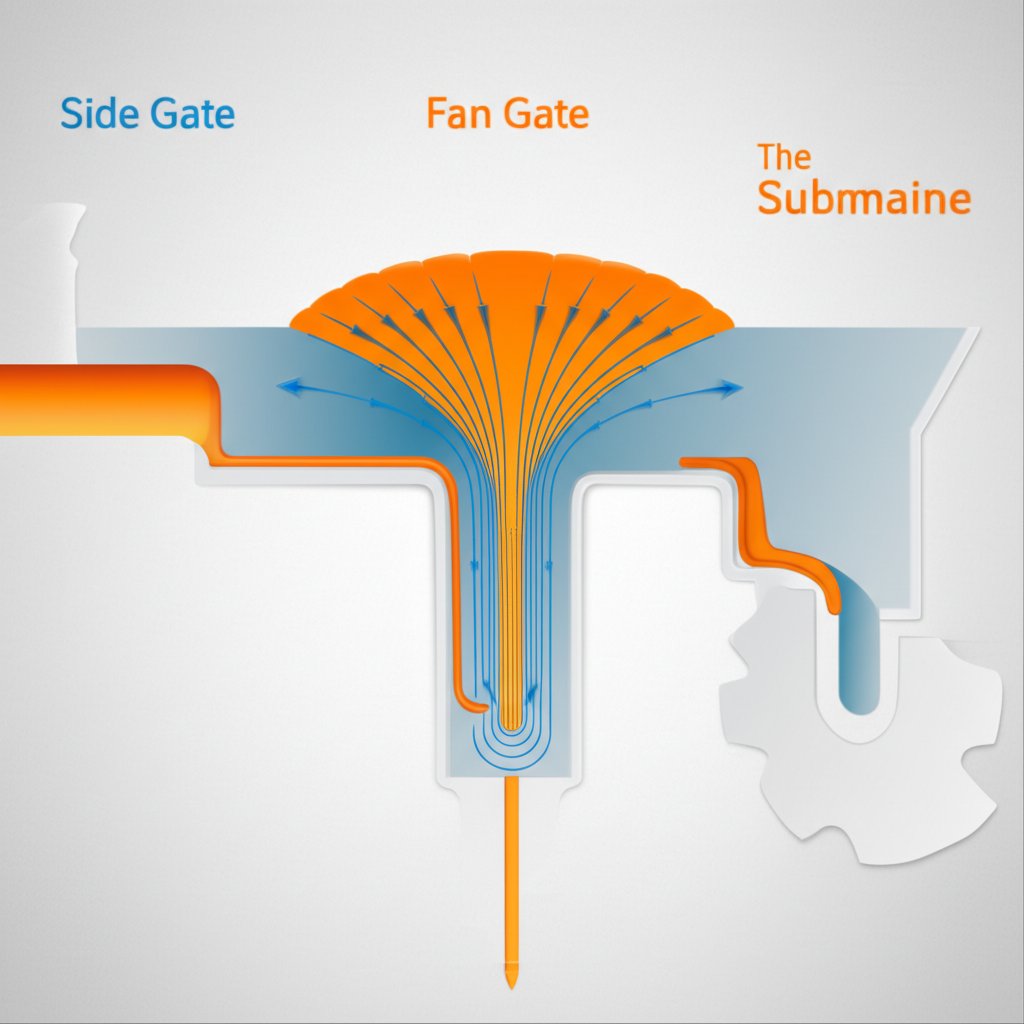
| Side/Edge Gate | Most common type; located on the parting line of the die. | Simple to design and manufacture; easy to remove. | Can cause turbulence if not properly designed; may not be ideal for complex geometries. |
| Fan Gate | A wide, thin gate that spreads the metal flow over a larger area. | Reduces metal velocity and turbulence; ideal for filling large, flat sections. | More difficult to remove; can be prone to freezing at the thin edges. |
| Submarine/Tunnel Gate | Located below the parting line, tapering to a small point at the cavity. | Automatically shears off during ejection, reducing secondary operations. | More complex to machine; limited to smaller parts and certain materials. |
Ultimately, achieving a robust final component depends on a deep understanding of material properties and process parameters. Expertise in high-performance metal forming, such as that demonstrated by Shaoyi (Ningbo) Metal Technology in their precision automotive forging, underscores the importance of rigorous process control. While die casting and forging are different processes, the shared goal is creating high-integrity parts through meticulous design and quality management. A checklist for die casting design should always include:
- Alloy Selection: Consider the fluidity, solidification range, and thermal properties of the metal.
- Part Geometry: Analyze wall thickness, complexity, and cosmetic requirements.
- Flow Simulation: Use software to predict metal flow, identify potential problem areas, and optimize the design before cutting steel.
- Machine Capabilities: Ensure the shot speed, pressure, and clamp tonnage are adequate for the part and gating design.
- Thermal Management: Plan for die cooling channels to control the solidification rate and prevent defects.
The Critical Role of Gate Location in Casting Quality
Beyond its size and shape, the strategic placement of the gate is one of the most critical decisions in die casting design. The location where molten metal enters the cavity dictates the entire filling pattern, influences the thermal gradient across the part, and ultimately determines the presence or absence of critical defects. A well-placed gate ensures a progressive, uniform fill, while a poorly placed one can doom a part from the start.
The primary rule, as noted in multiple engineering resources, is to position the gate at the thickest sections of the part. This principle ensures that these areas, which take the longest to solidify, are continuously fed with molten metal under pressure, preventing shrinkage porosity. Placing a gate at a thin section can cause the metal to freeze prematurely, blocking the flow and leading to a defect known as a cold shut, where two streams of metal fail to fuse properly.
Furthermore, the gate's location must be chosen to direct the flow of metal in a way that pushes air and gases ahead of it and out through vents and overflows. As explained by experts at Diecasting-mould, the gate should be positioned to avoid direct impingement on cores or delicate sections of the die, which can cause erosion of the tool and introduce turbulence. The flow should be directed along the walls of the cavity to promote a smooth, laminar fill.
Gate Location Scenarios: Good vs. Bad
-
Bad Location: Gating into a thin wall section far from the part's center of mass.
Resulting Defect: High risk of premature freezing, leading to incomplete fill (misrun) or cold shuts. The flow path is long and inefficient. -
Good Location: Gating into the thickest wall section of the part.
Benefit: Ensures the area with the highest material volume is fed last and under pressure, effectively counteracting shrinkage porosity and ensuring a dense, solid casting. -
Bad Location: Positioning the gate where it causes two flow fronts to collide head-on in a critical cosmetic area.
Resulting Defect: Creates a visible weld line, which is a structural weak point and a surface imperfection. -
Good Location: Placing the gate to encourage a single, continuous flow path that terminates at an overflow.
Benefit: Pushes air and contaminants ahead of the flow front and out of the cavity, resulting in a clean, dense part with minimal trapped gas.
In some cases, a single gate is insufficient for large or complex parts. A multi-gate system may be necessary to ensure complete filling. However, this adds complexity, as the gates must be balanced to fill their respective sections simultaneously to avoid creating internal weld lines where the flow fronts meet.
Troubleshooting: Common Defects Caused by Poor Gating System Design
A significant percentage of all die casting defects can be traced back to a suboptimal gating system. When engineers encounter issues like porosity, surface blemishes, or incomplete parts, the runner and gate design should be one of the first areas investigated. Understanding the direct link between a specific design flaw and the resulting defect is crucial for effective troubleshooting and process optimization.
For instance, porosity, the presence of small voids within the casting, is often caused by excessive turbulence. When molten metal churns violently within the runner or as it enters the gate, it traps air and other gases, which then become locked in the part as it solidifies. A gate that is too small for the required flow rate can act like a spray nozzle, atomizing the metal and exacerbating this issue. The solution often involves increasing the gate area, smoothing the runner path, or redesigning the gate's angle of entry to promote a less chaotic fill.
Another common issue is cold shuts or misruns, where the mold cavity does not fill completely. This typically occurs when the molten metal cools too quickly and loses its fluidity before reaching the farthest points of the cavity. This can be caused by a runner system that is too long, allowing excessive heat loss, or a gate that is too thin, restricting flow and causing the metal to freeze prematurely. Modifying the design to shorten the flow path or increase the gate thickness can often resolve this problem.
Gating System Troubleshooting Guide
| Defect Observed | Potential Gating System Cause | Recommended Design Modification |
|---|---|---|
| Gas Porosity | Excessive turbulence from high gate velocity; runners with sharp corners; poor gate location trapping air. | Increase gate area to reduce velocity; add radii to runner corners; relocate gate to push air toward overflows/vents. |
| Shrinkage Porosity | Gate freezes before the casting solidifies, preventing proper feeding of thick sections. | Increase gate thickness; relocate gate to the thickest section of the part. |
| Cold Shuts / Misruns | Low metal temperature at the gate due to a long runner; gate is too thin, causing premature freezing. | Shorten runner length; increase runner and gate cross-section; increase injection speed. |
| Flash | Excessive pressure caused by a gate that is too small, requiring higher injection pressure to fill. | Enlarge gate area to allow filling at a lower, more controlled pressure. |
| Surface Blisters | Trapped gas just below the surface, often caused by a turbulent fill pattern from a poorly directed gate. | Change gate angle and location to promote a smooth, laminar flow along the die walls. |
A systematic approach to diagnostics is key. When a defect appears, engineers should analyze the part to determine the defect's location and nature, then use flow simulation software or empirical analysis to correlate it with the gating design. Small, iterative changes to the runner or gate, followed by careful inspection of the results, are the most effective way to diagnose and solve these persistent manufacturing challenges.

Frequently Asked Questions
1. What is the gate and runner in casting?
In casting, the runner is a channel that transports molten material from the main sprue toward the part cavity. The gate is the specific opening between the end of the runner and the part cavity itself. The runner's job is distribution, while the gate's job is to control the final entry of the material, influencing its speed, direction, and flow pattern.
2. What is a runner in casting?
A runner is a channel machined into the die steel that serves as a pathway for molten metal. Its primary function is to distribute the metal from a central point (the sprue) to one or more gates that feed the mold cavities. A well-designed runner system maintains the metal's temperature and pressure while minimizing turbulence.
3. What is the gate in die casting?
The gate in die casting is the final, and often smallest, section of the channel system before the molten metal enters the actual part shape (the cavity). Its design is critical because it controls the velocity and flow characteristics of the metal as it fills the mold. The gate must be large enough to fill the part quickly but small enough to freeze off properly and be easily removed from the finished part.
4. What is a die runner?
A die runner is simply another term for the runner system within a die casting mold. It refers to the entire network of channels that guide the molten alloy from the sprue to the gates. The term emphasizes that these channels are an integral part of the die tool itself.