 Small batches, high standards. Our rapid prototyping service makes validation faster and easier —

Deep Draw Die Design Guidelines: 9 Essential Points For Flawless Parts
What Deep Draw Die Design Really Means for Precision Manufacturing
When you're tasked with producing seamless cylindrical cups, oxygen tanks, or automotive components with exceptional depth-to-diameter ratios, deep draw die design becomes your most critical success factor. Unlike conventional stamping where metal is cut or bent, the deep drawing process transforms flat sheet metal into hollow, three-dimensional shapes through controlled plastic flow. The die geometry you specify determines whether material compresses smoothly into form or tears under excessive stress.
Defining Deep Draw Die Design in Modern Manufacturing
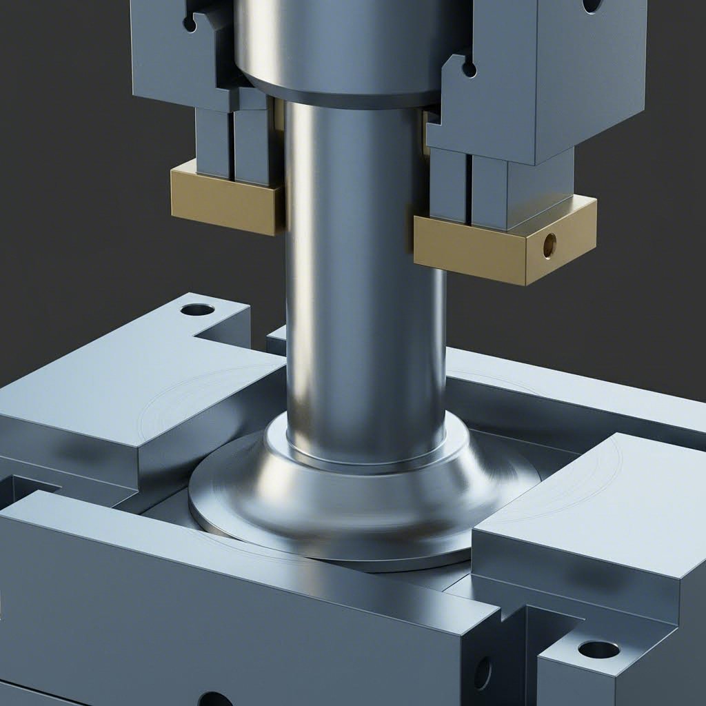
What is deep drawing, exactly? It's a metal forming operation where a punch forces a flat blank through a die cavity, creating depth that exceeds the part's diameter. According to The Fabricator, one of the biggest misconceptions is that metal stretches into shape. In reality, properly executed deep draw operations involve minimal stretching. The metal actually thickens through plastic flow as compressive forces push material inward toward the punch.
This distinction matters for your die design approach. You're engineering tooling that controls compression and flow, not stretch. Every radius, clearance, and surface finish specification influences how effectively metal transitions from a flat blank into your target geometry.
Why Die Design Determines Part Quality
Your die geometry directly controls three critical outcomes:
- Material flow patterns - Punch and die radii determine where metal compresses versus stretches
- Part geometry accuracy - Clearances and draft angles dictate dimensional consistency
- Production efficiency - Proper design minimizes draw stages and eliminates costly rework
The relationship between your punch position and blank edge is particularly crucial. Metal in compression resists flow. If your draw punch sits too far from the blank edge, the compressed zone becomes too large, flow resistance exceeds tensile strength, and tearing occurs near the punch nose.
The draw ratio - the relationship between blank diameter and punch diameter - is the fundamental principle governing deep draw success. Exceed your material's limiting draw ratio, and no amount of lubricant or press force adjustment will prevent failure.
This technical reference provides the specific parameters, formulas, and troubleshooting approaches you need for successful die design. Whether you're exploring deep drawing ideas for new product development or optimizing existing tooling, you'll find actionable guidelines backed by proven engineering principles. The sections ahead cover draw ratio limits by material, blank size calculations, radius specifications, multi-stage planning, and defect resolution strategies that transform your designs from theoretical concepts into production-ready tooling.
Draw Ratio Limits and Reduction Percentages by Material
You've established that draw ratio governs success in deep drawing operations. But what specific limits apply to deep drawing steel versus aluminum deep drawing or stainless steel deep drawing? Without precise numerical parameters, you're left guessing. This section provides the exact values you need to calculate staging requirements and prevent material failure.
Maximum Draw Ratios by Material Type
The limiting draw ratio (LDR) formula is straightforward:
LDR = D / d, where D equals blank diameter and d equals punch diameter (cup internal diameter)
This ratio indicates how large a blank can successfully form with a specific punch size. According to Toledo Metal Spinning, this formula serves as the starting point for determining how many draws are required. However, the critical insight is that LDR values differ significantly across materials.
When the stamping process of sheet metal pushes beyond these limits, circumferential compressive stress exceeds what the material can tolerate. As Macrodyne Press explains, if the reduction during a deep draw exceeds the material's limit, the blank will stretch or tear near the punch nose. Flow resistance simply overwhelms tensile strength.
Here's what you need to know about material-specific parameters:
| Material Type | First Draw Ratio Limit | Subsequent Draw Reduction % | Recommended Annealing Threshold |
|---|---|---|---|
| Low-Carbon Steel (deep drawing steel sheet) | 2.0 - 2.2 | 25% - 30% | After 40% cumulative reduction |
| Stainless Steel (304/316) | 1.8 - 2.0 | 20% - 25% | After 30% cumulative reduction |
| Aluminum Alloys (1100, 3003) | 1.9 - 2.1 | 20% - 25% | After 35% cumulative reduction |
| Copper Alloys (C11000, C26000) | 2.0 - 2.3 | 25% - 30% | After 45% cumulative reduction |
Notice that stainless steel deep drawing presents the most challenging parameters. Its work-hardening characteristics mean lower first-draw ratios and earlier annealing requirements compared to carbon steel or copper.
Calculating Reduction Percentages for Multi-Stage Operations
When your total reduction requirement exceeds what a single draw can achieve, you'll need multiple stages. The calculation process follows a systematic approach that The Fabricator describes as essential for avoiding splitting, wrinkling, and surface defects.
Here's how to determine your reduction percentage:
Reduction % = (1 - Dc/Db) × 100
Where Dc equals cup diameter and Db equals blank diameter.
Imagine you're producing a 4-inch diameter cup from a 10.58-inch blank. Your calculation shows approximately 62% total reduction needed. Since first-draw limits typically cap at 50% for most materials, you'll require multiple stages.
Consider this practical example from Macrodyne Press:
- First draw - Apply 50% reduction (LDR 2.0), reducing the 10.58-inch blank to a 5.29-inch intermediate diameter
- Second draw - Apply up to 30% reduction (LDR 1.5), achieving a 3.70-inch diameter
- Third draw - If needed, apply 20% reduction (LDR 1.25) for final dimensions
Since the target 4-inch diameter falls between the second-draw capability and the blank size, two stages complete the part successfully.
How Material Thickness Affects These Ratios
Thicker materials generally allow slightly higher draw ratios because they resist buckling more effectively. However, they also require greater blank holder force and more robust tooling. Thin-gauge deep drawing steel sheet may only achieve LDR values at the lower end of the published range.
The critical principle to remember: all surface area needed for the final part must exist in your first draw. As The Fabricator emphasizes, after the initial drawing station, surface area remains constant. You're redistributing existing material, not creating new material through subsequent operations.
With these draw ratio limits established, you'll next need precise blank size calculations to ensure adequate material for your target geometry.
Blank Size Calculation Methods and Formulas
You know your draw ratio limits. You understand reduction percentages. But how do you determine the exact blank diameter needed to produce your target cup or shell? Undersize your blank, and you'll run short of material. Oversize it, and you're wasting material while creating excess flange that complicates trimming. The process of deep drawing demands precision from the very first step.
The fundamental principle governing blank size calculation is volume constancy. As SMLease Design explains, the blank surface area must equal the finished part surface area. Metal doesn't disappear or appear during forming. It simply redistributes from a flat disc into your three-dimensional geometry.
Surface Area Method for Blank Development
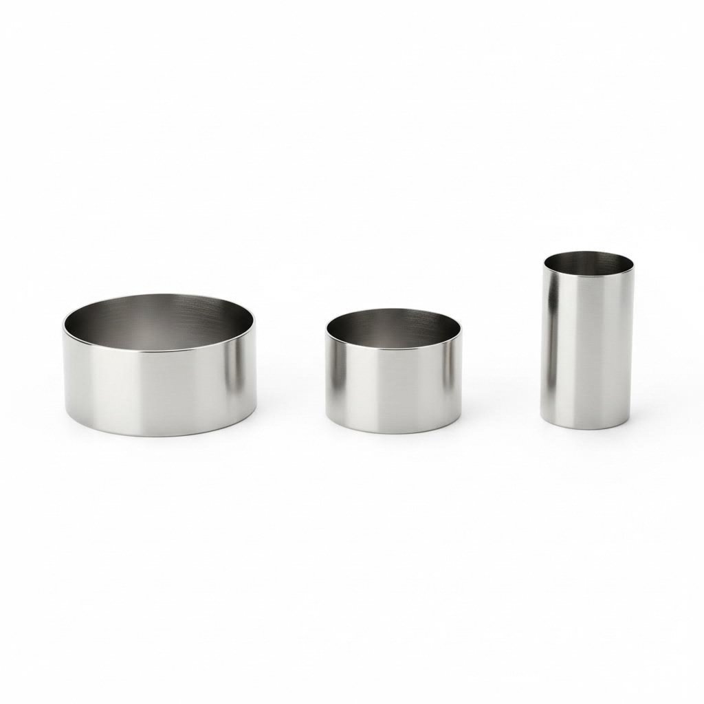
For cylindrical cups, the most common deep drawing sheet metal components, the mathematical approach is elegant. You're essentially equating two surface areas: the flat circular blank and the formed cup with its bottom and sidewall.
Consider a simple cylindrical cup with radius Rf and height Hf. The blank radius Rb can be calculated using this fundamental equation:
Rb = √[Rf × (Rf + 2Hf)]
This formula derives directly from setting the blank area (πRb²) equal to the cup area (πRf² + 2πRfHf). When you solve for Rb, you get the relationship shown above.
Let's walk through a practical example. Imagine you need to produce a cup with a 50mm diameter and 60mm depth. Following the drawing stamping calculation process:
- Cup radius (Rf) = 25mm
- Cup height (Hf) = 60mm
- Blank radius = √[25 × (25 + 120)] = √[25 × 145] = √3625 = 60.2mm
- Blank diameter = 60.2 × 2 = 120.4mm
This calculation gives you the theoretical minimum blank size. In practice, you'll need additional material for trimming and to compensate for thinning effects.
Accounting for Trim Allowance and Material Thinning
Real-world deep drawing manufacturing process requirements extend beyond the theoretical minimum. You need engineered scrap for clean trimming, plus compensation for wall thickness changes during forming.
Follow these sequential steps for production-ready blank dimensions:
- Calculate finished part surface area - Use geometry formulas for your specific shape. For cylinders: πd²/4 + πdh. For complex geometries, CAD software provides accurate surface area measurements.
- Add trim allowance - Industry practice recommends adding two times the metal thickness to the cup height before calculating. For a 0.010-inch material forming a 4-inch tall cup, your calculation height becomes 4.020 inches.
- Account for material thinning - Wall thinning of 10-15% typically occurs in the cup sidewall. Some practitioners add 3-5% to the calculated blank area as a thinning compensation factor.
- Determine final blank diameter - Apply the surface area formula with your adjusted dimensions, then round up to a practical cutting size.
According to The Fabricator, adding two times the metal thickness as extra trimming material represents good practice for ensuring clean final dimensions after forming.
When Simplified Formulas Fall Short
The equations above work beautifully for simple cylindrical cups. But what about stepped diameters, flanged parts, or irregular cross-sections? Complex geometries require different approaches.
You'll want to transition to CAD-based surface area calculations when:
- Your part includes multiple diameter changes or tapered sections
- Corner radii significantly affect surface area (the simple formula ignores punch nose radius)
- Non-axisymmetric shapes require developed blank patterns rather than circular blanks
- Tight tolerances demand precision beyond rule-of-thumb adjustments
For rectangular or irregular deep drawn parts, the blank shape itself may not be circular. These developed blanks require CAD analysis or finite element simulation to determine optimal starting geometry. Material anisotropy from rolling direction also influences blank shape optimization for non-round parts.
With your blank size calculated and material selected, the next critical design parameter involves punch and die radius specifications that control how smoothly metal flows during forming.
Punch and Die Radius Specifications for Optimal Material Flow
You've calculated your blank size and know your draw ratios. Now comes a parameter that can make or break your deep draw metal forming operation: tooling radii. The punch nose radius and die entry radius dictate how aggressively metal bends as it transitions from flange to sidewall. Get these specifications wrong, and you'll face either tearing from excessive stress concentration or wrinkling from inadequate material control.
Here's the core principle: metal flowing over sharp corners experiences localized strain that exceeds ductility limits. Conversely, radii that are too generous fail to guide material properly, allowing compressive buckling. Your job is finding the sweet spot for each material and thickness combination.
Punch Nose Radius Guidelines for Different Materials
The punch corner radius determines stress distribution at the most vulnerable location in your drawn part. According to Wikipedia's DFM analysis for deep drawing, the punch corner should be 4-10 times the sheet thickness. Maximum thickness reduction happens near the punch corner because metal flow decreases significantly in this region. Too sharp a corner results in cracks near the punch base.
Why does this location matter so much? During draw forming, material stretches over the punch nose while simultaneously being compressed circumferentially. This biaxial stress state concentrates at the radius transition. Insufficient radius creates a stress riser that initiates tearing before the draw completes.
Consider what happens with different radius values:
- Too small (below 4t) - Severe strain localization causes tearing at the punch nose, especially in work-hardening materials like stainless steel
- Optimal range (4-10t) - Stress distributes over a broader zone, allowing controlled thinning without failure
- Too large (above 10t) - Insufficient constraint allows the bottom to dome or wrinkle, and sidewall definition becomes poor
For deep drawing metal applications involving high-strength materials, err toward the larger end of this range. Softer materials like aluminum and copper can tolerate radii closer to 4t.
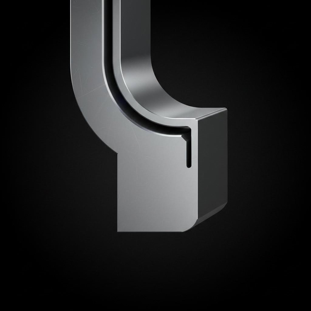
Die Entry Radius Specifications and Their Impact
The die corner radius controls how metal transitions from the horizontal flange region into the vertical die cavity. This is where compressive flange stresses convert to tensile wall stresses. As Wikipedia's deep drawing reference notes, the die corner radius should generally be 5-10 times the sheet thickness. If this radius is too small, wrinkling near the flange region becomes more prominent, and cracks develop due to sharp directional changes in metal flow.
The die radius presents a different challenge than the punch radius. Here, metal bends around an external corner while under compression from blank holder pressure. Insufficient radius causes:
- Excessive friction and heat generation
- Surface scoring and galling
- Localized tearing at the radius transition
- Increased drawing force requirements
Excessive die radius, however, reduces the effective blank holder contact area and allows premature material release from the flange zone, promoting wrinkling.
Radius Specifications by Material Thickness
The following table provides specific recommendations for deep draw forming operations across common material thickness ranges:
| Material Thickness Range | Recommended Punch Radius | Recommended Die Radius | Adjustment Notes |
|---|---|---|---|
| 0.010" - 0.030" (0.25-0.76mm) | 6-10 × thickness | 8-10 × thickness | Thin gauges need larger radii multiples to prevent tearing |
| 0.030" - 0.060" (0.76-1.52mm) | 5-8 × thickness | 6-10 × thickness | Standard range for most applications |
| 0.060" - 0.125" (1.52-3.18mm) | 4-6 × thickness | 5-8 × thickness | Thicker materials tolerate smaller multiples |
| 0.125" - 0.250" (3.18-6.35mm) | 4-5 × thickness | 5-6 × thickness | Heavy gauge; consider multiple draws for deep parts |
Material type also influences these specifications. Stainless steel typically requires radii at the upper end of each range due to its work-hardening behavior. Soft aluminum and copper can use values toward the lower end.
Die Clearance and Material Thickness Relationship
Beyond radii, the clearance between punch and die critically affects material flow. According to Wikipedia's DFM guidelines, clearance should be more than the metal thickness to avoid concentration of metal at the top of the die cavity. However, clearance should not be so large that metal flow becomes unrestricted, leading to wall wrinkling.
The practical guideline for draw forming clearance:
Clearance = Material Thickness + (10% to 20% of Material Thickness)
For a 0.040" material, your clearance would range from 0.044" to 0.048". This provides enough room for the naturally thickening sidewall while maintaining sufficient constraint to prevent buckling.
Some operations intentionally reduce clearance to "iron" the sidewall, producing more uniform thickness and better surface finish. As Hudson Technologies explains, tooling may be designed to intentionally thin or iron the sidewalls beyond natural tendency, adding dimensional stability and producing a more aesthetically pleasing case.
Corner Radius Considerations for Non-Cylindrical Parts
Rectangular and square deep drawn parts introduce additional complexity. The inside corner radii become the most critical design parameter. According to Hudson Technologies, the general rule is material thickness times two equals the smallest corner radius obtainable. Larger corner radii are desirable and may reduce the required number of draws.
Exceptions can be made with additional draw operations to further reduce corner radii, but caution is warranted. Increased material thinning and adjacent sidewall bow can occur when pushing corner radius limits.
For non-round parts, consider these guidelines:
- Minimum inside corner radius = 2 × material thickness (absolute minimum)
- Preferred inside corner radius = 3-4 × material thickness (reduces draw stages)
- Bottom corner radius = Follow punch radius guidelines (4-10 × thickness)
Radius Modifications for Subsequent Draw Operations
When your part requires multiple draw stages, radius specifications change between operations. First-draw tooling typically uses more generous radii to minimize work hardening and ensure successful material flow. Subsequent redraws can employ progressively tighter radii as the part approaches final dimensions.
A common progression:
- First draw - Die radius at 8-10 × thickness; punch radius at 6-8 × thickness
- Second draw - Die radius at 6-8 × thickness; punch radius at 5-6 × thickness
- Final draw - Die radius at 5-6 × thickness; punch radius at 4-5 × thickness
If annealing occurs between draws, you can reset to more aggressive radii since work hardening has been relieved. Without intermediate annealing, each successive draw operates on increasingly hardened material, requiring more conservative radii to prevent cracking.
With your tooling radii and clearances specified, the next consideration involves planning how many draw stages your part actually requires and sequencing reduction percentages across those operations.
Planning Multi-Stage Draw Operations and Reduction Sequences
You've determined your draw ratios, calculated blank sizes, and specified tooling radii. Now comes a question that separates successful deep draw stamping projects from costly failures: how many draw stages does your part actually require? Underestimate, and you'll tear material. Overestimate, and you're wasting tooling investment and cycle time.
The answer lies in systematic reduction planning. As The Library of Manufacturing explains, if the percent reduction exceeds 50%, you need to plan for redrawing operations. But that's just the starting point. Material properties, part geometry, and production requirements all influence your staging decisions.
Calculating Required Draw Stages
Your depth-to-diameter ratio provides the first indicator of staging complexity. Shallow parts with ratios below 0.5 typically form in a single draw. But what happens when you're producing deep cylindrical shells, battery casings, or pressure vessels with depth-to-diameter ratios exceeding 2.0?
Follow this systematic approach to determine your staging requirements:
- Determine total reduction required - Calculate the percentage reduction from blank diameter to final part diameter using the formula: Reduction % = (1 - Dp/Db) × 100. For example, a 10-inch blank forming a 4-inch diameter cup requires 60% total reduction.
- Apply material-specific reduction limits per stage - Reference your material's first-draw limit (typically 45-50% for steel, 40-45% for stainless). Subsequent draws allow progressively smaller reductions: 25-30% for second draws, 15-20% for third draws.
- Plan intermediate annealing if needed - When cumulative reduction exceeds your material's work-hardening threshold (30-45% depending on alloy), schedule stress-relief annealing between stages to restore ductility.
- Design progressive die stations - Map each reduction stage to a specific die station, accounting for material handling, lubrication requirements, and quality inspection points.
Consider a practical deep drawing operation example: you need a 3-inch diameter cup that's 6 inches deep from 0.040-inch low-carbon steel. Your depth-to-diameter ratio is 2.0, well beyond single-draw capability. Working backward from the finished dimensions, you might plan three stages with 48%, 28%, and 18% reductions respectively.
Reduction Planning Across Progressive Operations
Once you've determined the number of stages, sequencing the reductions properly becomes critical. The first draw does the heavy lifting, while subsequent draws refine geometry and achieve final dimensions.
Here's what successful deep drawing manufacturing operations consider for each stage:
- First draw - Establishes all surface area needed for the finished part. Maximum reduction occurs here (typically 45-50%). Tooling radii are most generous to minimize work hardening.
- Second draw (redraw) - Reduces diameter by 25-30% while increasing depth. Material has work-hardened from the first operation, so forces increase despite smaller reduction percentages.
- Third and subsequent draws - Further diameter reductions of 15-20% per stage. Evaluate whether annealing is necessary based on cumulative strain.
According to The Library of Manufacturing, when designing intermediate shapes, you should set the surface areas of the blank, intermediate parts, and final drawing to be equal. This volume constancy principle ensures you're redistributing existing material rather than attempting to create new surface area.
When Ironing Enters the Equation
Sometimes your deep draw manufacturing requirements call for wall thicknesses thinner than what standard drawing produces. This is where ironing comes into play. During standard deep drawing, sidewalls naturally thicken slightly as material compresses inward. Ironing reverses this by intentionally reducing clearance between punch and die to thin the walls.
Consider incorporating ironing when:
- Wall thickness uniformity is critical for your application
- You need walls thinner than the original blank thickness
- Surface finish requirements demand the burnishing effect ironing provides
- Dimensional consistency across production runs is paramount
Ironing typically occurs in the final draw stage or as a dedicated post-draw operation. The process adds dimensional stability and produces a more aesthetically pleasing surface, but requires additional tooling investment and careful force calculations.
Progressive Die Versus Transfer Die Configurations
Your staging plan must align with your press configuration. Two primary options exist for multi-stage deep drawing stamping: progressive dies and transfer dies. Each offers distinct advantages depending on your part geometry and production volume.
According to Die-Matic, progressive die stamping uses a continuous strip of metal fed through multiple stations where operations occur simultaneously. This approach excels for high-volume production of simpler geometries. The strip maintains part positioning automatically, reducing handling complexity.
Transfer die stamping, by contrast, moves individual blanks between stations using mechanical or hydraulic transfer systems. As Die-Matic explains, this method is best for complex parts requiring multiple forming operations or deep draws. The stop-and-go nature allows precise control over material flow at each station.
| Configuration | Best For | Limitations | Typical Applications |
|---|---|---|---|
| Progressive Die | High-volume, simpler geometries, thin materials | Limited draw depth, strip width constraints | Electronic components, small housings, shallow cups |
| Transfer Die | Complex parts, deep draws, tight tolerances | Slower cycle times, higher tooling complexity | Automotive panels, pressure vessels, deep cylindrical shells |
For deep draws with depth-to-diameter ratios exceeding 1.0, transfer die configurations typically provide better results. The ability to reposition blanks precisely at each station allows for the controlled material flow essential in multi-stage operations. Progressive dies work well when your first draw achieves most of the required depth and subsequent stations perform trimming, piercing, or minor forming operations.
With your staging plan and die configuration determined, the next critical factor involves calculating blank holder forces that prevent wrinkling while avoiding the excessive friction that causes tearing.
Blank Holder Force Requirements and Pressure Control
You've planned your draw stages and selected your die configuration. Now comes a parameter that demands precise calibration: blank holder force. Apply too little pressure, and compressive stresses buckle your flange into wrinkles. Apply too much, and friction prevents material flow, tearing your part near the punch nose. Finding the balance requires understanding both the physics involved and the variables you can control.
The blank holder serves one primary function: restraining the flange region while allowing controlled material flow into the die cavity. According to FACTON's deep drawing cost model, the blank holder area represents the material that must be held during deep drawing to avoid wrinkling. The pressure applied to this area, combined with friction, creates the resistance that controls how metal feeds into your forming operation.
Blank Holder Pressure Formulas and Variables
Calculating appropriate blank holder force isn't guesswork. The relationship between pressure, material properties, and geometry follows established principles. Here's the fundamental approach:
Blank Holder Force = Blank Holder Area × Blank Holder Pressure
Sounds simple? The complexity lies in determining the correct pressure value. Multiple factors influence your required blank holder pressure:
- Material strength - Higher tensile strength materials require greater holding force to control flow. As FACTON notes, tensile strength directly factors into blank holder pressure calculations.
- Blank diameter - Larger blanks create greater compressive forces in the flange zone, demanding proportionally higher restraint.
- Draw depth - Deeper draws require sustained pressure throughout a longer stroke, affecting both force magnitude and system design.
- Friction coefficient - Lubrication quality directly impacts how much force translates into material restraint versus heat generation.
- Drawing ratio - Higher ratios concentrate more compressive stress in the flange, requiring increased holding pressure.
A common starting formula for blank holder pressure ranges from 0.5 to 1.5 MPa for mild steel, with adjustments based on your specific material and geometry. Stainless steel typically requires pressures toward the higher end due to its work-hardening characteristics. Aluminum and copper alloys often work well at lower pressures.
The blank holder area calculation itself depends on your blank size and die geometry. You're essentially calculating the annular ring between your die opening and the blank edge. As the draw progresses, this area decreases, which explains why variable pressure systems offer advantages for deep draws.
Balancing Wrinkling Prevention with Tear Risk
According to research published in the CIRP Annals, the predominant failure modes in deep drawing are wrinkling and fracture, and in many cases these defects may be eliminated by appropriate control of Blank Holding Force. This finding underscores why BHF calibration represents such a critical design parameter.
Here's the physics at play: during deep drawn metal stamping, circumferential compressive stresses develop in the flange as material flows radially inward. Without adequate restraint, these stresses cause the flange to buckle upward, creating wrinkles. However, excessive restraint prevents the material from flowing at all, and tensile stresses near the punch exceed the material's strength, causing tears.
The research notes that wall wrinkling is particularly challenging because the sheet is unsupported by the tool in this region. Suppression of wall wrinkles through blank holder force control is more difficult than preventing flange wrinkles. This means your pressure settings must account for where defects are most likely to appear.
How do you know when your blank holder pressure is incorrect? Watch for these diagnostic indicators:
- Wrinkling patterns - Circumferential buckles in the flange zone indicate insufficient pressure; wall wrinkles suggest more complex flow control issues
- Edge tearing - Cracks initiating from the blank edge signal excessive friction from too-high pressure
- Uneven wall thickness - Asymmetric thinning patterns reveal non-uniform pressure distribution across the blank holder surface
- Surface scoring - Galling marks on the flange indicate excessive pressure combined with inadequate lubrication
- Punch nose tearing - Fractures near the cup bottom suggest material cannot flow freely enough to relieve tensile stress
If you're seeing wrinkles, your instinct might be to increase pressure dramatically. Resist this urge. Incremental adjustments of 10-15% allow you to approach optimal pressure without overshooting into tear-inducing territory.
Variable Blank Holder Pressure Systems
For complex deep draw metal parts, constant pressure throughout the stroke often proves inadequate. As The Fabricator explains, electronic shimming systems provide the most flexibility in blank and metal flow control for deep-drawing operations. These systems allow blank holder pressure adjustments to be made anywhere around the perimeter of the drawn shape at any point during the press stroke.
Why does variable pressure matter? Consider what happens during a draw:
- At stroke start, the full blank area requires restraint against wrinkling
- As material flows into the die, flange area decreases progressively
- Maintaining constant force on a shrinking area means effective pressure increases
- This rising pressure can prevent material from flowing during the critical final portion of the draw
Variable pressure systems address this by reducing force as the draw progresses, maintaining optimal pressure rather than optimal force. According to The Fabricator, these systems can also compensate for changes in metal thicknesses that occur during the drawing process, eliminating the need for a running spot on the blank holder.
Die Cushion Requirements and Nitrogen Spring Alternatives
Your blank holder force must come from somewhere. Three primary options exist, each with distinct characteristics for deep drawn metal stamping applications.
Press cushions represent the traditional approach. As The Fabricator notes, hydraulic cushions can exert the tremendous blank holder forces needed for stretch drawing parts such as automobile hoods and outer door panels. These systems supply force through air or cushion pins that transfer pressure evenly throughout the blank holder surface.
However, press cushions demand maintenance vigilance. The Fabricator warns that if air pins are damaged, bent, or uneven, binder deflection can occur, causing a poor fit between the die face and blank holder that may result in loss of metal control. Similarly, dented or dirty cushion surfaces compromise pressure uniformity regardless of pin accuracy.
Nitrogen springs offer a self-contained alternative that mounts directly in the die. These gas-charged cylinders provide consistent force throughout their stroke and require no external pressure supply. For metal forming coining and similar precision operations, nitrogen springs deliver repeatability that air systems sometimes cannot match.
Advantages of nitrogen springs include:
- Compact installation within die structure
- Consistent force output independent of press cushion condition
- Easy replacement and maintenance
- Predictable performance across production runs
The trade-off? Nitrogen springs provide fixed force characteristics. You cannot adjust pressure during the stroke without changing spring specifications. For parts requiring variable blank holder force profiles, press cushion systems with programmable control offer greater flexibility.
Stock lifter cylinders represent another option, particularly for progressive die applications. According to The Fabricator, these ready-to-install gas springs can absorb more side thrust and abuse than conventional cylinders. They come with pre-tapped holes for mounting stock rails, streamlining die construction.
When selecting your pressure system, match complexity to requirements. Don't invest in expensive electronic shimming systems when simple nitrogen springs will suffice. Conversely, don't expect to successfully draw complex geometries with basic urethane pressure systems that lack the force capacity and control precision needed for demanding applications.
With blank holder force properly calibrated, you're positioned to produce consistent parts. But what happens when defects still appear? The next section provides systematic troubleshooting approaches for diagnosing and correcting the wrinkling, tearing, and surface quality issues that challenge even well-designed tooling.
Deep Draw Defect Troubleshooting and Root Cause Analysis
You've calibrated your blank holder force, specified your tooling radii, and planned your reduction sequence. Yet defects still appear on your parts. What's going wrong? The answer lies in systematic diagnosis. Every wrinkle, tear, and surface imperfection tells a story about your process. Learning to read these failure patterns transforms frustrating scrap into actionable intelligence for die design improvements.
Deep drawn stamping defects fall into predictable categories, each with distinct visual signatures and root causes. According to Metal Stamping O, most deep draw stamping issues come from a combination of tooling and designing problems. By examining the finished product, the trained eye can tell a clear story regarding the quality of the process. Your task is developing that trained eye.
Diagnosing Wrinkling and Tearing Failures
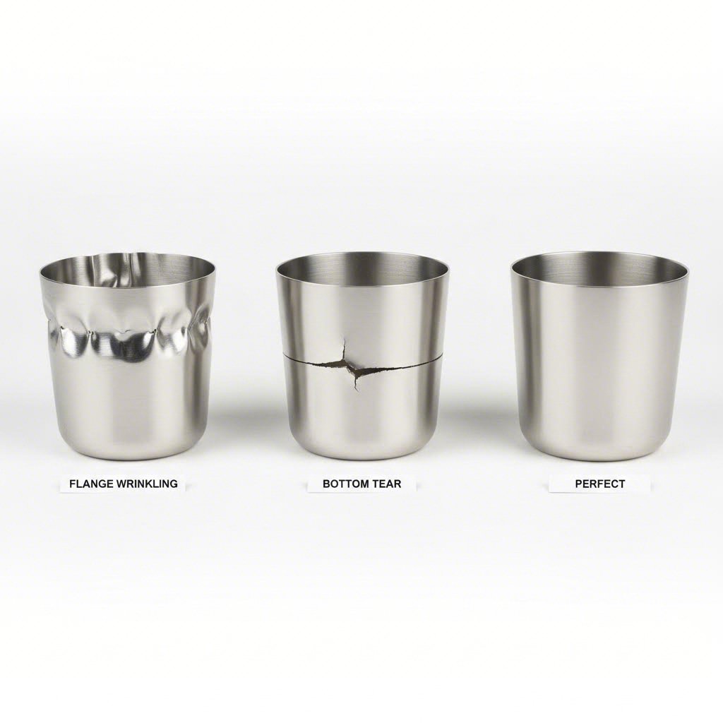
Wrinkling and tearing represent opposite ends of the material flow spectrum. Wrinkles indicate uncontrolled compression. Tears signal excessive tension. Understanding where each defect appears on your part points directly to the causative die design parameter.
Wrinkling diagnosis: Where do wrinkles form on your part? Flange wrinkles appearing at the blank edge typically indicate insufficient blank holder pressure. As Metal Stamping O explains, if the holder is unbalanced, too tight, or if the blank contains a burr on the holding edge, then the metal won't flow properly, forming tell-tale wrinkles across the upper edge. Wall wrinkles occurring in the unsupported region between blank holder and punch suggest excessive clearance or inadequate die radius.
Solutions for wrinkling defects:
- Increase blank holder pressure incrementally (10-15% adjustments)
- Check blank holder parallelism and correct any tilt
- Inspect blank edges for burrs that prevent proper seating
- Reduce die clearance to provide better wall support
- Verify uniform pressure distribution across the entire blank holder surface
- Consider draw beads to increase material restraint in problem areas
Tearing diagnosis: Tear location reveals the stress concentration source. Cracks near the punch nose indicate material cannot flow freely enough to relieve tensile stress. According to Breaking AC's sheet metal defect analysis, excessive metal-forming forces by punches result in over-deformation, tearing, and cracks in the stamped parts.
Edge tears originating from the blank periphery suggest different problems. Metal Stamping O notes that bottom cracks are mainly attributed to the status of the blank and blank holder. Nicking or galling of the surface can reduce the material flow into the die, resulting in cracks forming at the bottom of the cup.
Solutions for tearing defects:
- Reduce blank holder pressure to allow freer material flow
- Increase punch nose radius to distribute stress over a larger area
- Increase die entry radius to reduce friction during material transition
- Verify punch-die clearance isn't too tight for your material thickness
- Improve lubrication to reduce friction-induced tensile stress
- Consider annealing if work hardening from previous operations has reduced ductility
- Reduce draw ratio by adding additional draw stages
Solving Earing and Surface Quality Issues
Not all defects involve catastrophic failure. Earing creates uneven cup height that requires excessive trimming. Surface defects compromise appearance and may affect part function. Both trace back to controllable process variables.
Earing explained: When you examine a drawn cup and notice the rim height varies around the circumference, you're seeing earing. As Breaking AC explains, the earing defect refers to an uneven height around the rim of the drawn part. The main reason is neglecting the work and die materials compatibility.
However, material anisotropy plays the primary role. Sheet metal from rolling operations has directional properties. Grains elongate in the rolling direction, creating different mechanical properties at 0°, 45°, and 90° to that direction. During metal deep drawing, material flows more easily in some directions than others, creating the characteristic "ears" at predictable angular positions.
Mitigation strategies for earing:
- Select materials with low planar anisotropy values (r-value close to 1.0 in all directions)
- Use developed blank shapes that compensate for directional flow differences
- Increase trim allowance to accommodate expected ear height variation
- Consider cross-rolled materials for critical applications
- Adjust blank holder pressure to influence flow uniformity
Surface quality issues: Scratches, galling, orange peel texture, and die lines all indicate specific process problems. Galling occurs when insufficient lubrication allows metal-to-metal contact between blank and tooling. Orange peel texture suggests excessive grain growth from over-annealing or material with unsuitable grain structure for your draw depth.
Solutions for surface defects:
- Improve lubrication quality and coverage, especially in high-friction zones
- Polish die and punch surfaces to reduce friction and prevent material pickup
- Select appropriate tool steel and surface treatments for your material combination
- Verify material grain size is appropriate for your draw severity
- Check for debris or contamination on blank holder and die surfaces
- Consider protective films for parts requiring pristine surface finish
Comprehensive Defect Reference Table
The following table consolidates defect diagnosis into a quick-reference format for deep draw steel, stainless steel, and other common materials:
| Defect Type | Visual Indicators | Root Causes | Corrective Actions |
|---|---|---|---|
| Flange Wrinkling | Circumferential buckles at blank edge; wavy flange surface | Insufficient blank holder pressure; holder misalignment; burrs on blank edge | Increase BHF; check holder parallelism; deburr blanks; add draw beads |
| Wall Wrinkling | Buckles in cup sidewall between flange and punch nose | Excessive die clearance; inadequate die radius; thin material | Reduce clearance; increase die radius; consider ironing operation |
| Punch Nose Tearing | Cracks originating at cup bottom radius | Punch radius too small; draw ratio exceeded; excessive BHF; insufficient lubrication | Increase punch radius; add draw stage; reduce BHF; improve lubrication |
| Edge Tearing | Cracks initiating from blank periphery | Excessive BHF; burrs on blank edge; galling on blank holder | Reduce BHF; deburr blanks; polish blank holder; improve lubrication |
| Earing | Uneven cup rim height; peaks at 45° intervals typical | Material planar anisotropy; inconsistent blank holder pressure | Select isotropic material; use developed blanks; increase trim allowance |
| Uneven Wall Thickness | Localized thin spots; asymmetric thickness distribution | Punch-die misalignment; non-uniform BHF; material variation | Realign tooling; verify BHF uniformity; check material consistency |
| Galling/Scoring | Linear scratches; material pickup on tooling | Inadequate lubrication; incompatible tool material; excessive pressure | Improve lubricant; apply surface coatings; reduce contact pressure |
| Orange Peel | Rough, textured surface resembling citrus skin | Excessive grain size; over-annealing; severe deformation | Specify finer grain material; control annealing parameters |
| Springback | Part dimensions differ from die geometry; walls bow outward | Elastic recovery after forming; high-strength materials | Overbend tooling to compensate; increase holding time at bottom of stroke |
Systematic Diagnostic Approach
When defects appear in your deep drawing of steel or other materials, resist the urge to make multiple simultaneous adjustments. Instead, follow a methodical process:
- Inspect defect location precisely - Document exactly where on the part the defect occurs. Photograph the failure pattern for reference.
- Analyze failure pattern - Is it symmetric or localized? Does it occur at consistent angular positions? Does it appear at the same stroke position?
- Trace to die design parameter - Use the defect table above to identify likely root causes based on defect type and location.
- Make single-variable adjustments - Change one parameter at a time to isolate the effect. Document each adjustment and result.
- Verify correction stability - Run sufficient parts to confirm the fix works consistently across production, not just on a few samples.
According to Metal Stamping O, gaining insight into the deep draw method, along with understanding how to examine a finished part, is essential when it comes to the decision-making process. This diagnostic capability proves invaluable during both initial die development and ongoing production troubleshooting.
Remember that some defects interact. Increasing blank holder force to eliminate wrinkles may push your process toward tearing. The goal is finding the operating window where both failure modes are avoided. For challenging geometries, that window may be narrow, requiring precise control systems and consistent material properties.
With troubleshooting fundamentals established, modern die design increasingly relies on simulation tools to predict and prevent defects before cutting steel. The next section explores how CAE analysis validates your design decisions and accelerates the path to production-ready tooling.
CAE Simulation Integration for Modern Die Design Validation
You've mastered draw ratios, specified tooling radii, and developed troubleshooting expertise. But imagine predicting every defect before cutting a single piece of tool steel. That's precisely what CAE simulation delivers. Modern sheet metal stamping design has evolved beyond trial-and-error. Finite element analysis now validates your design decisions virtually, identifying wrinkling, tearing, and thinning problems while your die exists only as digital geometry.
Why does this matter for your deep draw projects? According to research published in the International Journal of Engineering Research & Technology, a reduction in the number of trials would directly influence the cycle time for development. A shorter cycle time can be planned with due utilization of software tools that would predict the trial results without actually conducting the same. The simulation offered during the stamping process lends important insights into modifications needed in the die and component design.
Integrating Simulation into Die Design Validation
Finite element analysis transforms your metal stamping die design workflow from reactive to predictive. Instead of building tooling, running trials, discovering defects, modifying steel, and repeating, you iterate digitally until the simulation confirms success. Only then do you commit to physical tooling.
The physics behind stamping design simulation involves discretizing your blank into thousands of elements, each tracking stress, strain, and displacement as the virtual punch advances. The software applies your material's mechanical properties, friction coefficients, and boundary conditions to calculate how every element deforms throughout the stroke.
What can simulation predict before you build anything?
- Material flow patterns - Visualize exactly how metal moves from flange into die cavity, identifying areas of excessive compression or tension
- Thinning distribution - Map thickness changes across your entire part, spotting potential failure zones before they cause scrap
- Wrinkling tendency - Detect compressive buckling in flanges and unsupported wall regions that would require tooling modifications
- Springback prediction - Calculate elastic recovery after forming to design compensation into your die geometry
- Blank holder force optimization - Determine ideal pressure profiles that prevent both wrinkling and tearing
- Draw bead effectiveness - Test restraint configurations virtually before committing to tooling changes
The research confirms this approach works. As the IJERT study notes, the virtual validation of the die using simulation software should address given problems during the design stage. While the die is manufactured, trials and testing address validation as the physical tool is tried out for checking component quality.
Understanding Forming Limit Diagrams
Among simulation outputs, the Forming Limit Diagram stands as your most powerful defect prediction tool. According to Stamping Simulation, the primary purpose of any forming simulation is to check how the material behaves prior to building the stamping tool. Originally a 1965 graduate research project, the FLD aimed to determine what triggers localized necking and splitting in sheet metal forming and whether splitting could be predicted in advance.
Here's how FLD analysis works: simulation calculates strain in two directions (major and minor axis) for every element in your formed part. These strain pairs plot as points on a graph. The Forming Limit Curve, unique to your specific material and thickness, divides safe territory from failure zones.
What does the FLD tell you about your deep draw presses setup?
- Points below the curve - Safe forming conditions with adequate margin
- Points approaching the curve - Risk zone requiring design attention
- Points above the curve - Failure is certain; splitting will occur at these locations
- Points in the compression zone - Wrinkling tendency that may require increased blank holder pressure
As the Stamping Simulation reference explains, the Forming Limit Curve is primarily determined by the n-value and thickness of a given material. Results illustrate calculated areas of material yielding, necking amounts, and compression zones where wrinkles and folds may form. With this information, countermeasures can be made to die face design before any steel is cut.
From CAE Analysis to Production-Ready Tooling
Simulation doesn't replace physical validation. It accelerates your path to successful physical validation. The workflow follows an iterative optimization loop:
- Create initial die design - Develop geometry based on your calculated draw ratios, radii specifications, and blank size
- Run forming simulation - Apply material properties, friction values, and process parameters
- Analyze results - Review FLD plots, thickness distribution maps, and wrinkling indicators
- Identify problem areas - Locate elements exceeding safe limits or approaching failure thresholds
- Modify design parameters - Adjust radii, clearances, blank holder pressure, or draw bead configuration
- Re-run simulation - Verify modifications resolved issues without creating new problems
- Iterate until acceptable - Continue optimization until all elements fall within safe forming limits
- Release for tooling manufacture - Commit to physical die construction with confidence
According to the IJERT research, the die would be considered validated upon inspecting physical trial components for presence and magnitude of defects. Low occurrence and consistency in desirable characteristics would be the basis for validation. Simulation dramatically reduces the iterations needed to reach this validation milestone.
Key Simulation Checkpoints in Your Design Process
Not every design decision requires full simulation analysis. However, certain checkpoints benefit substantially from virtual validation:
- Blank development verification - Confirm calculated blank size provides adequate material without excessive waste
- First-draw feasibility - Validate that your initial reduction stays within material limits
- Multi-stage transition analysis - Verify material condition between draw stages remains formable
- Corner radius evaluation - Check strain concentration at tight radii on non-cylindrical parts
- Springback compensation design - Calculate overbend required to achieve target dimensions
- Blank holder force optimization - Determine pressure profiles that maximize process window
- Draw bead placement - Test restraint configurations for complex geometries
The Stamping Simulation resource notes that virtual circle grid plots can be compared to actual circle grid experiments to determine simulation accuracy. This correlation between virtual and physical results builds confidence in simulation-guided design decisions.
Leveraging Professional Simulation-Integrated Services
While simulation software has become more accessible, extracting maximum value requires expertise in both the software capabilities and deep draw process fundamentals. Deep draw stamping companies increasingly differentiate themselves through simulation competency.
What should you look for in deep draw metal stamping manufacturers offering simulation-integrated services? First-pass approval rates provide a concrete metric. When a die design partner achieves 93% first-pass approval, you're seeing the tangible result of simulation-validated design. That percentage translates directly into reduced development time, lower tooling modification costs, and faster production ramp-up.
Quality certifications matter equally. IATF 16949 certification ensures that simulation validation integrates into a broader quality management system with documented procedures and consistent execution. The simulation itself is only valuable when performed correctly with realistic parameters.
For automotive applications and other demanding deep draw projects, professional die design services that leverage simulation before cutting steel represent a strategic advantage. Shaoyi's automotive stamping die solutions demonstrate this approach, combining advanced CAE simulation capabilities with rapid prototyping in as little as five days. Their engineering team delivers simulation-validated tooling tailored to OEM standards, reducing the costly iterations that plague traditional trial-and-error development.
The IJERT research concludes that simulation lends important insights into modifications needed in the die and component to effect a simplified and productive die. Normally, a forming die calls for refined design parameters for ensuring smooth passage through the trial phase. Simulation provides those refined parameters before you invest in physical tooling.
With simulation capabilities integrated into your die design workflow, you've addressed the most significant source of development delays and costs. The final piece of the puzzle involves selecting appropriate die materials and surface treatments that ensure your validated design delivers consistent performance across production volumes.
Die Material Selection and Surface Treatment Guidelines
You've validated your die design through simulation and optimized every forming parameter. Now comes a decision that determines whether your tooling delivers consistent results for thousands of parts or fails prematurely: die material selection. The punch, die, and blank holder materials you specify directly influence wear rates, surface finish quality, and ultimately your cost per part across production runs.
According to the ASM Handbook on Metalworking, the selection of material for a drawing die is aimed at the production of the desired quality and quantity of parts with the least possible tooling cost per part. This principle guides every material decision you'll make. The most wear-resistant option isn't always optimal. You're balancing initial cost, maintenance requirements, and expected production volume.
Tool Steel Selection for Deep Draw Die Components
Deep draw metal stamping operations subject tooling to severe conditions. Blank holders experience abrasive contact with every stroke. Punches endure compressive loading while maintaining precise geometry. Dies must guide material flow while resisting the galling that occurs when similar metals contact under pressure.
What factors should drive your tool steel selection? Consider these variables:
- Production volume - Low-volume prototype runs justify different materials than million-piece automotive programs
- Workpiece material - Deep drawing stainless steel creates more tooling wear than mild steel or aluminum
- Part complexity - Complex geometries concentrate stress at specific locations requiring enhanced wear resistance
- Surface finish requirements - Decorative parts demand tooling that maintains polish throughout production
- Maintenance capability - Some materials require specialized heat treatment or grinding equipment for refurbishment
The ASM Handbook on Press-Forming Dies reviews production variables that influence selection among ferrous, nonferrous, and even plastic die materials. For deep drawn metal applications, tool steels dominate, but the specific grade matters enormously.
| Die Material | Application | Hardness Range (HRC) | Wear Resistance | Best Use Cases |
|---|---|---|---|---|
| D2 Tool Steel | Dies, punches, blank holders | 58-62 | Excellent | High-volume production; abrasive materials; deep drawing steel sheet |
| A2 Tool Steel | Punches, moderate-wear dies | 57-62 | Good | Medium-volume production; good toughness for impact loading |
| M2 High-Speed Steel | Punches requiring hot hardness | 60-65 | Very Good | High-speed operations; elevated temperature applications |
| Carbide (Tungsten Carbide) | High-wear inserts, ironing rings | 75-80 (HRA equivalent) | Outstanding | Million-piece runs; stainless steel deep drawing; precision dimensions |
| O1 Tool Steel | Prototype dies, low-volume punches | 57-62 | Moderate | Short runs; easy machinability; bendable metal sheets for crafts applications |
Notice how production volume influences every selection. For prototype tooling or short runs involving bendable metal sheets for crafts or similar low-volume applications, O1 or even mild steel with surface hardening may suffice. For automotive production volumes, D2 or carbide inserts become economically justified despite higher initial costs.
Material Pairing Considerations Between Punch and Die
Selecting individual components isn't enough. How punch and die materials interact affects galling resistance, wear patterns, and overall tool life. According to the ASM Handbook, galling represents a typical cause of wear in deep-drawing tooling. When similar materials contact under the pressures and sliding conditions of metal stamping design, microscopic welding and tearing occur.
Consider these pairing principles:
- Avoid identical hardness - When punch and die share the same hardness, both wear rapidly. Specify 2-4 HRC difference between components.
- Harder component contacts workpiece critical surface - If part exterior appearance matters most, make the die harder. If interior surface is critical, harden the punch.
- Consider dissimilar materials - Bronze or aluminum bronze blank holders paired with tool steel dies reduce galling tendency when drawing aluminum alloys.
- Match expansion coefficients - For precision deep draw metal stamping, similar thermal expansion between punch and die maintains clearances during production runs.
- Account for coating compatibility - Some surface treatments perform better against specific die steel substrates.
Surface Treatments and Coatings for Extended Die Life
Even the best tool steel benefits from surface enhancement. According to the ASM Handbook, options include surface coatings such as chromium plating, and surface treatments such as carburizing or carbonitriding for low-alloy steels, or nitriding and physical vapor deposition coating for tool steels. Each treatment addresses specific wear mechanisms.
Nitriding diffuses nitrogen into the steel surface, creating a hard case without dimensional change. As AZoM explains, nitriding boosts wear resistance and hardness of the tool surface. It's particularly ideal for applications involving abrasive materials. For deep drawing dies, nitriding extends life significantly when forming coated steels or high-strength alloys.
Chromium plating deposits a hard, low-friction surface layer. According to AZoM, hard chromium plating boosts surface hardness considerably, realizing values up to 68 HRC. It's particularly useful when forming structural grade steels, copper, carbon steels, and brass. The smooth chrome surface also improves part release and reduces lubricant requirements.
Titanium nitride (TiN) coating applies via physical vapor deposition, creating a gold-colored ceramic layer. AZoM notes that high hardness integrated with low friction properties guarantees significantly longer service life. TiN reduces galling tendency dramatically, making it valuable for deep drawing stainless steel where adhesive wear challenges uncoated tooling.
Titanium carbonitride (TiCN) offers a harder, lower-friction alternative to TiN. According to AZoM, it has good wear resistance combined with toughness and hardness. For deep draw metal applications requiring both abrasion resistance and impact toughness, TiCN provides an excellent balance.
Titanium aluminum nitride (TiAlN) excels in demanding conditions. AZoM describes it as having high oxidation stability and toughness, suitable for higher speeds while enhancing tool life. For high-volume deep drawn metal production where heat generation is significant, TiAlN maintains performance where other coatings degrade.
When Carbide Inserts Justify Their Cost Premium
Carbide tooling costs significantly more than hardened tool steel. When does this investment pay off? Several scenarios make carbide the economically superior choice:
- Production volumes exceeding 500,000 pieces - Carbide's extended life amortizes initial cost across enough parts to reduce per-piece tooling expense
- Tight dimensional tolerances - Carbide's wear resistance maintains critical dimensions far longer than steel, reducing adjustment frequency
- Abrasive workpiece materials - High-strength low-alloy steels and stainless grades accelerate steel die wear dramatically
- Ironing operations - The severe sliding contact during wall ironing destroys steel tooling rapidly
- Downtime sensitivity - When production interruptions cost more than tooling, carbide's reliability justifies premium pricing
Steel-bonded carbides offer a middle ground. According to the ASM Handbook, steel-bonded carbides provide wear resistance approaching solid carbide with better toughness and machinability. For complex die geometries that would be prohibitively expensive in solid carbide, steel-bonded alternatives deliver excellent performance.
Production Volume and Material Selection Economics
Your expected production quantity fundamentally shapes material decisions. Consider this progression:
Prototype and low-volume (under 1,000 pieces): Soft tool materials like mild steel or aluminum work for initial trials. Even unhardened O1 tool steel may suffice. The goal is validating part design, not maximizing tool life.
Medium-volume (1,000-100,000 pieces): Hardened A2 or D2 tool steels become standard. Surface treatments like nitriding or chrome plating extend life without excessive initial investment.
High-volume (100,000-1,000,000 pieces): Premium D2 with PVD coatings or carbide inserts at critical wear locations. The cost of tooling modifications during production runs justifies higher initial material investment.
Mass production (over 1,000,000 pieces): Carbide inserts, multiple backup die sets, and comprehensive surface treatment programs. Tooling becomes a capital asset requiring life-cycle cost analysis.
Partnering for Comprehensive Die Material Solutions
Die material selection doesn't exist in isolation. It integrates with every other design decision: radii specifications, blank holder force, surface finish requirements, and production schedule. Experienced die design partners consider material selection as part of holistic tooling solutions, balancing initial cost against production performance.
What distinguishes capable partners? Look for engineering teams that address material selection during design development, not as an afterthought. Rapid prototyping capabilities in as little as five days demonstrate the manufacturing flexibility to evaluate material options practically. Cost-effective tooling tailored to OEM standards reflects the experience to match material investment with actual production requirements.
Shaoyi's comprehensive mold design and fabrication capabilities exemplify this integrated approach. Their IATF 16949 certification ensures material selection decisions follow documented quality procedures. Whether your application demands carbide inserts for million-piece stainless steel production or economical hardened steel for prototype validation, comprehensive die design services deliver appropriate material solutions matched to your specific requirements.
Die material selection completes your deep draw die design guidelines toolkit. From draw ratio calculations through simulation validation and now material specification, you have the technical foundation for developing tooling that produces flawless parts consistently across production volumes.
Frequently Asked Questions About Deep Draw Die Design
1. What is the proper die clearance for deep drawing operations?
Die clearance should be 10-20% greater than material thickness to prevent metal concentration at the die top while maintaining wall control. For 0.040" material, specify 0.044"-0.048" clearance. Tighter clearances intentionally iron sidewalls for uniform thickness, while excessive clearance causes wall wrinkling. Professional die designers like Shaoyi use CAE simulation to optimize clearance for specific materials and geometries, achieving 93% first-pass approval rates.
2. How do you calculate blank size for deep drawing?
Calculate blank size using the volume constancy principle: blank surface area equals finished part surface area. For cylindrical cups, use the formula Rb = √[Rf × (Rf + 2Hf)], where Rb is blank radius, Rf is cup radius, and Hf is cup height. Add 2× material thickness for trim allowance and 3-5% for thinning compensation. Complex geometries require CAD-based surface area calculations for accuracy.
3. What causes wrinkling and tearing in deep drawn parts?
Wrinkling results from insufficient blank holder pressure allowing compressive buckling in the flange zone. Tearing occurs when excessive holder pressure or inadequate tooling radii prevent material flow, causing tensile stress to exceed material strength near the punch nose. Solutions include adjusting blank holder force incrementally, increasing punch/die radii to 4-10× material thickness, and improving lubrication. Simulation-validated designs prevent these defects before tooling manufacture.
4. How many draw stages are needed for deep drawing?
Stage requirements depend on total reduction percentage. First draws achieve 45-50% reduction, subsequent draws 25-30% and 15-20% respectively. Calculate stages by determining total reduction needed (blank diameter to final diameter), then dividing by material-specific limits per stage. Parts with depth-to-diameter ratios exceeding 1.0 typically require multiple stages. Plan intermediate annealing when cumulative reduction exceeds 30-45% depending on material.
5. What are the recommended punch and die radius specifications?
Punch nose radius should be 4-10× material thickness to distribute stress and prevent tearing. Die entry radius requires 5-10× thickness for smooth material transition. Thinner gauges need larger radius multiples. For 0.030"-0.060" material, specify punch radius at 5-8× and die radius at 6-10× thickness. Non-cylindrical parts require minimum inside corner radii of 2× thickness, with 3-4× preferred to reduce draw stages.