 Small batches, high standards. Our rapid prototyping service makes validation faster and easier —

Why Your Blanking Die Clearance Calculation Fails And How To Fix It

Understanding Blanking Die Clearance Fundamentals
Ever wondered why some stamped parts come out perfectly clean while others have rough edges, excessive burrs, or premature tool wear? The answer often lies in one critical factor: die clearance. Getting this fundamental calculation right can mean the difference between a smooth production run and costly quality issues.
What Is Die Clearance and Why Does It Matter
Imagine you're cutting paper with scissors. If the blades are too loose, the paper tears unevenly. If they're too tight, you struggle to cut at all. The same principle applies to metal stamping—except the stakes are much higher.
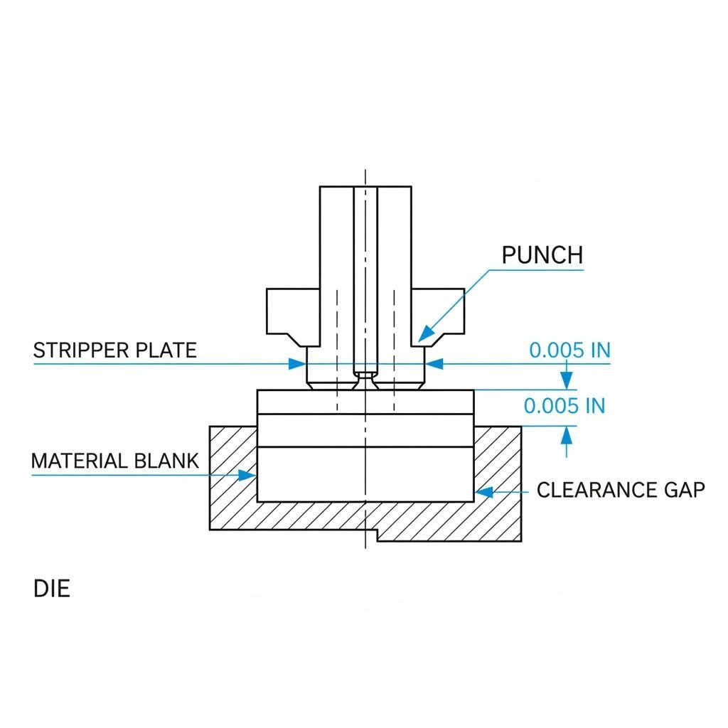
Die clearance is the gap between the punch and die edges during a blanking operation, typically expressed as a percentage of the material thickness per side. This precision gap directly determines how cleanly the material shears and separates during stamping.
When you're performing a blanking die operation, the punch pushes through the sheet metal while the die provides the cutting edge below. The clearance between these two components controls the fracture pattern, edge quality, and overall part dimensions. According to industry standards, this clearance generally ranges from 3% to 12% of material thickness per side, depending on the material being processed.
The Critical Gap Between Punch and Die
So what happens in that tiny gap? When the punch descends into the sheet metal, it creates a shearing action. The material first experiences penetration (where the punch pushes into the metal), followed by fracture (where the material breaks along the shear line). Proper clearance ensures these fracture lines from the punch and die meet cleanly in the middle of the material.
Here's why this matters for your operation:
- Part Quality: Correct clearance produces clean edges with minimal burr formation and consistent dimensions
- Tool Life: Optimal clearance reduces wear on your punch and die, potentially extending tool life by two-thirds compared to improper settings
- Production Efficiency: Proper clearance decreases stripping force requirements and reduces press load, allowing faster cycle times
- Cost Control: Fewer rejects, less tool replacement, and reduced downtime translate directly to your bottom line
Fundamentals of Blanking Die Clearance
Understanding clearance starts with recognizing it as a calculated specification—not a guess. The traditional "rule of thumb" of 5% per side, while historically common, no longer applies universally. With the emergence of higher strength steels and advanced materials in today's manufacturing environment, Dayton Progress notes that tensile strength and material thickness must both be considered when selecting clearance percentages.
The relationship works like this: as material tensile strength increases and sheet thickness grows, the load on your tooling increases significantly. A 10% clearance hole specification for soft aluminum will differ dramatically from what you'd need for high-strength steel of the same thickness.
Think of clearance selection as a balancing act. Too little clearance creates excessive tool wear, extreme stripping pressure, and oversized burrs. Too much clearance introduces vibration during piercing, potential quality inconsistencies, and increased roll-over on the cut edge. Just as engineers might use a creepage and clearance calculator for electrical safety spacing, precision die work demands equally careful calculation of mechanical clearances.
The good news? Once you understand the variables involved—material type, thickness, and desired edge quality—calculating proper clearance becomes a straightforward process. The sections ahead will walk you through the exact formulas and practical examples you need to get it right every time.
The Essential Clearance Calculation Formula
Now that you understand why clearance matters, let's tackle what most resources fail to provide: the actual mathematical methodology. Whether you're using a punch calculator for quick estimates or working through detailed die specifications, having the complete formula at your fingertips eliminates guesswork and ensures repeatable results.
The Complete Clearance Formula Explained
Ready for the formula that makes blanking die clearance calculation straightforward? Here it is:
Clearance (per side) = Material Thickness × Clearance Percentage
Sounds simple, right? It is—once you understand each component. For example, if you're working with 1.0 mm thick material and a 10% clearance percentage, your per-side clearance equals 0.10 mm. This means the gap between the punch edge and die edge measures 0.10 mm on each side of the cut.
But here's where many calculations go wrong: forgetting about total clearance. Since clearance exists on both sides of the punch, the total punch-to-die clearance equals twice the per-side value. Using our example above:
- Per-side clearance: 1.0 mm × 10% = 0.10 mm
- Total clearance: 0.10 mm × 2 = 0.20 mm
This distinction becomes critical when specifying punch and die dimensions. Miss it, and your tooling will be off by a factor of two.
Breaking Down the Calculation Variables
Every clearance calculator relies on the same core variables. Understanding each one ensures you select the right inputs for accurate results:
- Material Thickness (t): The actual gauge or thickness of your sheet metal workpiece, measured in millimeters or inches. This is your baseline measurement—every clearance calculation builds from it.
- Clearance Percentage (k): A coefficient typically ranging from 5% to 20%, determined by material properties and desired edge quality. Harder materials and production-focused applications use higher percentages; precision work demands lower values.
- Per-Side Clearance: The calculated gap at each cutting edge (t × k). This value applies to each side of the punch independently.
- Total Clearance: The complete gap between punch point and die opening (per-side clearance × 2). Use this when calculating final die dimensions.
When using a punch force calculator or die calculator, these same variables determine not just clearance but also the tonnage requirements and expected tool wear patterns. Getting them right from the start saves recalculation headaches later.
Per-Side vs Total Clearance Distinction
Why does this distinction trip up so many engineers? Because tooling suppliers, reference charts, and shop floor conversations often switch between per-side and total clearance without clarification.
Consider this practical example from Dayton Progress: with an engineered clearance of 10% on 1.0 mm thick material, you get a per-side clearance of 0.10 mm. If you're punching a 12.80 mm diameter hole, the die opening must be 13.00 mm—that's the punch size plus the total clearance (0.20 mm).
Here's a quick reference to keep the relationship clear:
| Clearance Type | Formula | Example (1.0 mm material, 10%) |
|---|---|---|
| Per-Side Clearance | Material Thickness × Clearance % | 1.0 × 0.10 = 0.10 mm |
| Total Clearance | Per-Side Clearance × 2 | 0.10 × 2 = 0.20 mm |
| Punch Size (blanking) | Part Size − Total Clearance | 13.00 − 0.20 = 12.80 mm |
| Die Size (piercing) | Hole Size + Total Clearance | 12.80 + 0.20 = 13.00 mm |
Notice how the application—blanking versus piercing—determines whether you subtract or add the clearance? Just as electrical engineers rely on a creepage clearance calculator to ensure proper isolation distances, die designers must apply clearance values correctly based on which tool surface defines the final dimension.
With the formula firmly in hand, the next critical step is selecting the right clearance percentage for your specific material. Different metals demand different approaches—and getting that percentage wrong undermines even the most careful calculations.
Material Properties and Clearance Percentage Selection
You've mastered the formula. You know the difference between per-side and total clearance. But here's where many calculations still fail: selecting the wrong clearance percentage for the material at hand. A 5% clearance that works beautifully for soft aluminum will destroy your tooling when applied to hardened steel. Understanding why different materials demand different percentages is the key to getting your die size calculator results right every time.
How Material Hardness Affects Clearance Selection
Think about what happens when your punch drives into sheet metal. The material doesn't simply split—it first deforms plastically, then fractures along shear planes. The critical question is: how much does your material resist that deformation before fracturing?
This resistance comes down to three interconnected properties:
- Hardness: Measures surface resistance to indentation. Harder materials fracture more abruptly, requiring larger clearances to accommodate the sudden separation.
- Tensile Strength: The maximum stress a material can withstand before breaking. According to MISUMI's technical guidance, workpiece materials with higher tensile strength require additional clearance to manage increased tooling loads.
- Ductility: How much a material can stretch before fracturing. Ductile materials like soft aluminum flow and deform easily, allowing tighter clearances. Brittle or hardened materials crack with minimal deformation, demanding more room to fracture cleanly.
Here's the practical takeaway: as material hardness and tensile strength increase, your clearance percentage must increase proportionally. Ignore this relationship, and you'll see excessive punch wear, poor edge quality, and potentially catastrophic tool failure.
Clearance Percentages for Common Sheet Metals
So what clearance percentage should you actually use? While standard die cutting tolerances provide general guidance, the specific material you're processing determines the optimal range. The table below summarizes recommended clearance percentages based on material type and hardness:
| Material Type | Typical Hardness (HRC/HB) | Tensile Strength Range | Recommended Clearance (% per side) |
|---|---|---|---|
| Soft Aluminum (1100, 3003) | <40 HB | 75-130 MPa | 3-5% |
| Hard Aluminum (6061, 7075) | 60-95 HB | 290-570 MPa | 5-7% |
| Mild Steel (1008, 1010) | 80-100 HB | 300-400 MPa | 5-8% |
| Medium Carbon Steel (1045) | 170-210 HB | 565-700 MPa | 8-10% |
| Stainless Steel (304, 316) | 150-200 HB | 515-620 MPa | 8-10% |
| High-Strength Steel (HSLA) | 200-250 HB | 550-700 MPa | 10-12% |
| Hardened Materials (Spring Steel) | 40-50 HRC | 1000+ MPa | 10-12% |
Notice the pattern? Soft materials cluster at 3-5%, while hardened materials push toward 10-12%. This isn't arbitrary—it reflects the fundamental physics of how these materials fracture under shear loading.
Matching Clearance to Material Properties
Selecting the right percentage requires more than just identifying your material type. Consider these practical factors when using a metal die punch setup:
- Material condition matters: Annealed aluminum behaves differently than work-hardened aluminum of the same alloy. Always verify your material's actual temper designation.
- Coating effects: Galvanized or coated steels may require slightly increased clearance to account for the coating thickness and its effect on fracture behavior.
- Thickness interactions: The clearance percentage remains relatively constant, but thicker materials amplify any errors in percentage selection. A 1% mistake on 3 mm steel creates three times the dimensional error compared to 1 mm stock.
- Edge quality requirements: If your application demands exceptional edge finish—similar to how a pcb clearance calculator might optimize for precise electrical spacing—you may reduce clearance slightly within the recommended range, accepting increased tool wear as a tradeoff.
Here's a real-world scenario: you're stamping brackets from 1.5 mm 304 stainless steel. The table suggests 8-10% clearance. Starting at 9% gives you:
- Per-side clearance: 1.5 mm × 9% = 0.135 mm
- Total clearance: 0.135 mm × 2 = 0.27 mm
If trial parts show excessive burr, you'd increase toward 10%. If edge rollover becomes problematic, you'd decrease toward 8%. The percentage ranges provide your starting point—production feedback fine-tunes the final value.
Modern manufacturing has evolved beyond the old "10% for everything" approach. As MISUMI's engineers note, fine-tuning with higher clearance values of 11-20% for certain applications can considerably reduce tooling strain and increase operational life. Just as specialized tools like a pcb clearance calculator help electronics engineers optimize their designs, understanding material-specific clearance percentages lets you optimize your size die specifications for both quality and longevity.
With material properties and clearance percentages now clear, there's one more critical distinction that trips up even experienced die designers: how to apply these calculations differently for blanking versus piercing operations.
Blanking Versus Piercing Clearance Differences
Here's where even experienced tooling engineers make costly mistakes. You've calculated your clearance percentage correctly. You know your material properties inside and out. But if you apply that clearance value to the wrong component, your parts will be consistently oversized or undersized—and you'll spend hours troubleshooting a problem that never existed in your math.
The critical distinction? Whether you're blanking or piercing determines which tool—the punch die or the die opening—gets sized to the final part dimension. Get this backwards, and every single part coming off your press will be wrong.
Blanking vs Piercing Clearance Application
Let's break down what actually happens in each operation:
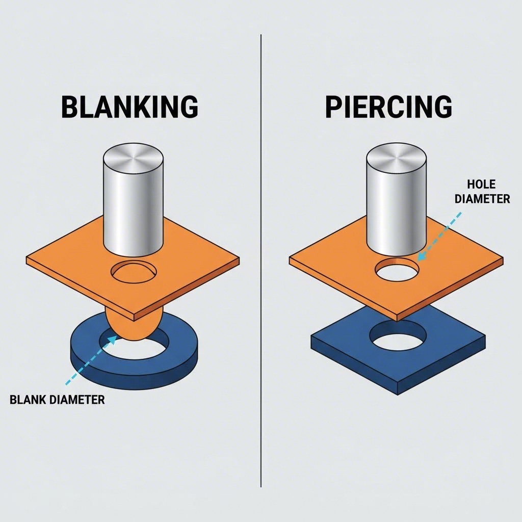
Blanking produces an external shape—the piece that falls through the die becomes your finished part. Think of stamping out circular discs, bracket outlines, or component blanks. The material surrounding your part is scrap.
Piercing creates an internal feature—you're punching a hole, slot, or cutout. The piece that falls through becomes scrap, while the surrounding material is your part.
This seemingly simple distinction completely changes how you apply clearance values. Why? Because the tool that contacts the final part surface must be sized to your target dimension. The other tool gets the clearance adjustment.
Which Tool Determines Final Dimensions
Imagine you're producing a 75 mm diameter blank from cold rolled steel. According to industry calculation standards, for a blanking operation the die diameter would be 75 mm (matching the required part size), while the punch diameter calculates to 74.70 mm after subtracting clearance.
Here's the logic:
- In blanking: The die cut punch creates the outer edge of your finished part. The die opening must match your target dimension exactly—it's the master reference. The punch is made smaller by the total clearance amount.
- In piercing: The punch creates the inner edge of your hole. The punch must match your target hole size exactly—it's the master reference. The die and punch opening is made larger by the total clearance amount.
Think of it this way: whatever surface the finished part retains contact with during the cut determines the critical dimension. In blanking, your part drops through the die—so the die sets the size. In piercing, your part surrounds the punch before it withdraws—so the punch sets the size.
Applying Clearance Correctly for Each Operation
Now for the formulas that make this practical. These are the calculations you'll use every time you specify punch and die tooling:
-
For Blanking Operations:
Die Size = Part Size (the die matches your target dimension)
Punch Size = Part Size − (2 × Per-Side Clearance) -
For Piercing Operations:
Punch Size = Hole Size (the punch matches your target dimension)
Die Size = Hole Size + (2 × Per-Side Clearance)
Let's apply this to a real scenario. You need to blank a 50 mm diameter disc from 1.5 mm mild steel (using 7% clearance per side):
- Per-side clearance: 1.5 mm × 7% = 0.105 mm
- Total clearance: 0.105 mm × 2 = 0.21 mm
- Die diameter: 50.00 mm (matches part requirement)
- Punch diameter: 50.00 − 0.21 = 49.79 mm
Now suppose you're piercing a 10 mm hole in that same part:
- Per-side clearance: 1.5 mm × 7% = 0.105 mm
- Total clearance: 0.105 mm × 2 = 0.21 mm
- Punch diameter: 10.00 mm (matches hole requirement)
- Die opening: 10.00 + 0.21 = 10.21 mm
Notice how the clearance calculation stays identical—only the application changes. The punch die relationship follows a consistent logic once you understand which tool defines your critical dimension.
Getting this distinction right from the start prevents the frustrating scenario of perfectly calculated clearances producing consistently wrong parts. With the formulas now clear, the next step is seeing them applied in complete worked examples—walking through entire calculations from material selection to final tooling dimensions.
Worked Calculation Examples in Metric and Imperial
Theory is valuable, but nothing solidifies understanding like working through complete examples from start to finish. Whether you're using a punch calculator for quick estimates or manually verifying critical tooling specifications, these step-by-step walkthroughs demonstrate exactly how to apply everything you've learned. Let's work through real-world scenarios using both measurement systems.
Step-by-Step Blanking Calculation Example
Before diving into numbers, here's the systematic approach that eliminates calculation errors every time:
- Identify your material and thickness - Know exactly what you're cutting and its gauge
- Select the appropriate clearance percentage - Match material properties to recommended ranges
- Calculate per-side clearance - Apply the core formula: thickness × percentage
- Determine punch and die dimensions - Apply clearance correctly based on operation type (blanking or piercing)
This structured approach works whether you're sizing sheet metal punches and dies for production runs or prototyping new components. The key is following each step in sequence—skipping ahead often introduces errors that compound through the final dimensions.
Metric Calculation Walkthrough
Let's work through a complete blanking example using metric measurements. You need to produce circular washers with a 40 mm outer diameter and a 20 mm center hole from 2.0 mm thick 304 stainless steel.
Step 1: Identify material and thickness
Material: 304 Stainless Steel
Thickness: 2.0 mm
Required blank diameter: 40 mm
Required hole diameter: 20 mm
Step 2: Select clearance percentage
From our material properties table, 304 stainless steel typically requires 8-10% clearance per side. We'll use 9% as our starting point—a balanced choice that provides good edge quality while protecting tooling.
Step 3: Calculate per-side clearance
Per-side clearance = Material Thickness × Clearance Percentage
Per-side clearance = 2.0 mm × 9% = 0.18 mm
Total clearance = 0.18 mm × 2 = 0.36 mm
Step 4: Determine punch and die dimensions
For the blanking operation (creating the 40 mm outer diameter):
- Die diameter = Part size = 40.00 mm
- Punch diameter = Part size − Total clearance = 40.00 − 0.36 = 39.64 mm
For the piercing operation (creating the 20 mm center hole):
- Punch diameter = Hole size = 20.00 mm
- Die opening = Hole size + Total clearance = 20.00 + 0.36 = 20.36 mm
Your complete tooling specification: 39.64 mm blanking punch, 40.00 mm blanking die, 20.00 mm piercing punch, and 20.36 mm piercing die opening. Using a standard calculation approach, you can verify these dimensions produce the exact finished part geometry required.
Imperial Measurement Example
Now let's tackle the same calculation methodology using imperial measurements—essential for shops working with U.S. material specifications and tooling standards.
Scenario: You're blanking rectangular brackets measuring 3.000" × 2.000" from 0.060" thick mild steel (1010 series).
Step 1: Identify material and thickness
Material: 1010 Mild Steel
Thickness: 0.060" (approximately 16 gauge)
Required blank dimensions: 3.000" × 2.000"
Step 2: Select clearance percentage
Mild steel typically requires 5-8% clearance per side. For standard production work, 6% provides an excellent balance between edge quality and tool life.
Step 3: Calculate per-side clearance
Per-side clearance = 0.060" × 6% = 0.0036"
Total clearance = 0.0036" × 2 = 0.0072"
Step 4: Determine punch and die dimensions
For this blanking operation:
- Die opening = Part size = 3.000" × 2.000"
- Punch size = Part size − Total clearance = 2.9928" × 1.9928"
When working with imperial fractions, you might encounter questions like whether 23/32 vs 5/8 represents a meaningful difference in clearance applications. In this example, our 0.0072" total clearance equals approximately 7/1000"—small but critical for proper shearing action. Similarly, understanding that comparisons like is 15/32 the same as 5/8 (they're not—15/32 equals 0.469" while 5/8 equals 0.625") helps prevent specification errors when converting between fractional and decimal dimensions.
According to The Fabricator's technical guidance, even small clearance variations of 0.001" to 0.002" can measurably affect hole size and punch withdrawal friction. This explains why precise calculation matters more than rough estimates—especially when specifying tooling for high-volume production.
Punching force consideration: While calculating clearance, many engineers also run a punching force calculator to verify press tonnage requirements. For our mild steel example, the cutting force would be approximately:
Force = Perimeter × Thickness × Shear Strength
Force = (3.0" + 3.0" + 2.0" + 2.0") × 0.060" × 40,000 psi ≈ 24,000 lbs
This confirms standard press capacity requirements while your clearance calculations ensure clean cuts at that force level.
With these worked examples as templates, you can confidently tackle any blanking die clearance calculation—whether metric or imperial, simple circles or complex geometries. But what happens when your calculations look perfect on paper yet trial parts still show quality issues? The next section addresses how clearance affects real-world part quality and what symptoms indicate when adjustments are needed.
Clearance Effects on Part Quality and Tool Life
Your calculations look perfect on paper. The formula is correct, the material percentage matches industry recommendations, and the punch and die dimensions check out mathematically. Yet trial parts come off the press with excessive burrs, rough edges, or signs of premature tool wear. What went wrong?
The answer often lies in understanding how clearance directly influences real-world outcomes—not just dimensional accuracy, but the entire quality profile of your stamped parts. Think of clearance as the invisible hand guiding how metal fractures, separates, and releases from your tooling. Get it right, and everything flows smoothly. Get it wrong, and the evidence shows up immediately on your parts.
How Clearance Impacts Burr Formation
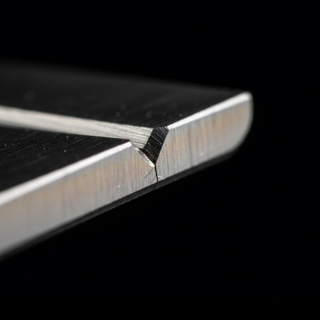
Burrs are perhaps the most visible symptom of clearance problems. These sharp raised edges along stamping edges form when the material doesn't shear cleanly—and their characteristics tell you exactly what's happening inside your die.
When clearance is too tight, something counterintuitive occurs. You might expect tighter gaps to produce cleaner cuts, but the opposite happens. According to Dayton Lamina's extensive testing, when die clearance is insufficient, the upper and lower fracture planes essentially miss each other. Instead of meeting cleanly in the middle of the material, they create secondary cracks and double breaks. The result? Larger, more irregular burrs that require additional deburring operations.
With optimal clearance, the fracture planes from the punch and die cutting edges connect precisely. This produces a consistent burnished land—typically about one-third of the material thickness—followed by an even fracture zone. Burr height minimizes naturally because the metal separates along its intended shear path.
Excessive clearance creates its own burr problems. While the fracture planes connect, the larger gap allows more material deformation before separation. This produces a rough fracture plane, smaller burnished area, and burrs that form from excessive rollover rather than incomplete shearing.
Edge Quality and Clearance Relationship
Beyond burrs, edge quality encompasses the entire cut surface—burnish zone, fracture zone, and any secondary shear marks. Metal punches and dies in optimal condition with correct clearance produce edges with predictable characteristics you can actually read like a diagnostic tool.
The slug—that piece of material punched out and dropped through the die—tells the complete story. As Dayton's technical research explains, slugs are mirror images of the hole quality. Examining your slugs reveals:
- Optimal clearance: Consistent burnished land (approximately 1/3 of thickness), even fracture plane aligned with the land, minimal burr
- Insufficient clearance: Irregular fracture plane, uneven burnished land, secondary shear marks, pronounced burr
- Excessive clearance: Rough fracture plane, small burnished area, excessive rollover on the hole edge
For applications requiring secondary operations—threading, press-fitting, or precision assembly—edge quality directly impacts downstream processes. Just as engineers might use a piston to valve clearance calculator to ensure proper engine component interaction, dies and punches must be specified with clearances that produce edges suitable for their intended function.
Extending Tool Life Through Proper Clearance
Here's where clearance calculations pay dividends over thousands of production cycles. Incorrect clearance doesn't just affect part quality—it dramatically accelerates tool wear and can lead to premature failure.
The mechanics work like this: with tight clearance, the material grabs the punch during withdrawal. This creates excessive stripping force that acts like sandpaper on your punch surface with every cycle. According to HARSLE's technical documentation, improper clearance significantly increases friction and tool stress, accelerating wear and potentially causing premature tool failure.
Dayton Lamina's research quantifies this dramatically. A regular 5% clearance can produce holes 0.0001" or smaller than the punch point, creating a press-fit condition during withdrawal. Their engineered clearance approach produces slightly larger holes, eliminating as much as two-thirds of punch wear. That translates directly to extended intervals between sharpening and replacement.
The table below summarizes how different clearance conditions affect every aspect of part quality and tool performance:
| Clearance Condition | Burr Formation | Edge Quality | Tool Wear | Stripping Force |
|---|---|---|---|---|
| Too Tight (<5%) | Large, irregular burrs from secondary shear | Uneven burnish, secondary fracture marks | Accelerated—punch grabbing increases abrasion | Excessive—material grips punch during withdrawal |
| Optimal (5-12% depending on material) | Minimal burr height | Consistent 1/3 burnish, clean fracture plane | Normal—clean separation reduces friction | Minimal—clean release from material |
| Too Loose (>12-15%) | Rollover-type burrs | Rough fracture, small burnish zone | Moderate—vibration can cause chipping | Low but with potential slug pulling issues |
Notice the interconnection between these factors. The clearance lab of your production floor provides constant feedback—if you know how to read it. Excessive stripping force shows up as punch coating wear or increased cycle times. Poor edge quality manifests as rejected parts or downstream assembly problems. Tool wear appears in maintenance logs and replacement costs.
The bottom line? Optimal clearance isn't just about hitting a target number—it's about achieving the balance that produces acceptable parts while maximizing the productive life of your tooling. When trial parts show symptoms of incorrect clearance, systematic troubleshooting helps identify whether your calculations need adjustment or other factors are at play.
Verification and Troubleshooting Your Calculations
So your blanking die clearance calculation is complete, your tooling is built to specification, and you've run your first trial parts. Now what? Even the most precise calculations require validation against real-world results. The gap between theoretical clearance values and actual production performance often reveals variables that formulas alone can't capture.
Think of verification as the final step that transforms calculations into production-ready specifications. Whether you're working with new punch and die tooling or evaluating existing dies from punch dies suppliers, systematic verification ensures your clearance values actually deliver the quality and tool life you expect.
Verifying Your Clearance Calculations
Before troubleshooting problems, confirm your calculated clearances match what's actually on the shop floor. This sounds obvious, but dimensional drift during manufacturing, improper grinding, or simple documentation errors can create gaps between specification and reality.
Here's a practical verification checklist:
- Measure punch diameter: Use calibrated micrometers to verify the punch measures within tolerance of your calculated dimension
- Measure die opening: Pin gauges or bore micrometers confirm die cavity dimensions match specifications
- Calculate actual clearance: Subtract measured punch diameter from measured die opening, then divide by two for per-side clearance
- Compare to specification: Document any deviation between calculated and measured values—even 0.01 mm differences affect results
- Check concentricity: Verify punch and die alignment using dial indicators or optical comparators
According to industry inspection guidelines, regularly inspecting tooling equipment has several challenges—above all it can be time consuming and expensive. However, the quality of your stamped parts depends directly on the quality of your tooling. Skipping verification to save time often creates larger problems downstream.
Interpreting Trial Run Results
Your trial parts speak volumes if you know how to listen. Each quality characteristic provides diagnostic information about whether your clearance values need adjustment—and in which direction.
Start by examining these key indicators:
- Burr height and location: Excessive burr on the die side suggests insufficient clearance; burr with excessive rollover indicates too much clearance
- Burnished zone ratio: A clean burnish covering roughly one-third of material thickness confirms optimal clearance. Smaller burnish zones signal excessive clearance; irregular or double burnish marks indicate tight clearance
- Slug appearance: The punched-out material mirrors hole quality. Examine slugs for consistent fracture planes and even edges
- Dimensional accuracy: Blanks oversize or holes undersize may indicate punch or die cut puncher wear rather than clearance issues
- Part flatness: Excessive distortion near cut edges can result from clearance-related material stress
As blanking process troubleshooting experts note, poor edge quality often results from incorrect clearance between punch and die, inconsistent material thickness or hardness, and punch and die wear. Distinguishing between these causes requires methodical analysis of multiple trial parts.
Making Incremental Clearance Adjustments
When trial results indicate clearance issues, resist the urge to make dramatic changes. Incremental adjustments—typically 1-2% of material thickness—allow you to isolate the effect of clearance from other variables.
Follow this systematic adjustment approach:
- Document baseline conditions: Record current clearance values, material batch information, press settings, and resulting part quality
- Adjust one variable: Modify only the clearance—keep material, speed, and lubrication constant
- Run sufficient samples: Collect at least 20-30 parts to establish statistical validity
- Evaluate results: Compare edge quality, burr formation, and dimensional stability against baseline
- Iterate if needed: Make additional incremental adjustments until quality targets are met
Compensating for spring-back: Some materials, particularly high-strength steels and stainless alloys, exhibit spring-back after blanking that affects dimensional accuracy. According to advanced die compensation methods, the formed part affected by springback is measured against a reference part, and the die is modified to counter the difference. While this applies primarily to forming operations, blanking dies cutting tight-tolerance parts may require similar compensation strategies—slightly oversizing or undersizing tooling to achieve target dimensions after material relaxation.
Compensating for material variation: Real-world material batches vary in thickness, hardness, and surface condition. If your calculated clearance works perfectly for one batch but produces problems with another, consider:
- Measuring incoming material properties and adjusting clearance calculations accordingly
- Specifying tighter material tolerances from suppliers
- Building adjustability into die design for quick clearance modifications
Fine-tuning based on production feedback: Production runs generate valuable data that trial runs cannot. Track metrics like:
- Parts between sharpening cycles
- Reject rate trends over time
- Stripping force measurements (if equipped)
- Tool wear patterns during maintenance
This production feedback loop transforms your initial calculations into optimized specifications. The goal isn't perfect first-time accuracy—it's establishing a systematic process that converges quickly on optimal clearance values for your specific combination of material, tooling, and quality requirements.
With verification complete and adjustments dialed in, many manufacturers seek additional optimization through advanced simulation and precision tooling solutions that can predict clearance performance before cutting steel.
Advanced Tools and Precision Die Solutions
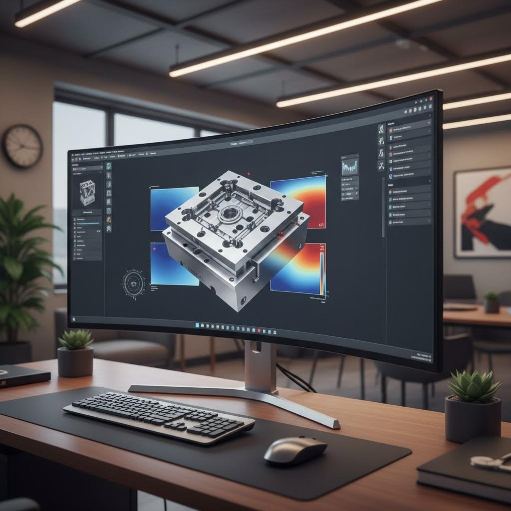
Manual calculations and trial-and-error adjustments have long been the backbone of blanking die clearance optimization. But what if you could predict clearance effects before cutting a single piece of steel? Modern CAE simulation and precision manufacturing technologies are transforming how engineers approach clearance optimization—reducing costs, accelerating development timelines, and eliminating the guesswork that traditionally plagued die development.
CAE Simulation for Clearance Optimization
Imagine testing dozens of clearance configurations without building a single prototype die. That's exactly what advanced finite element (FE) simulation enables. According to recent research published in Heliyon, numerical simulation of the blanking process allows engineers to study the influence of blanking clearance on punch force-displacement curves and cut edge quality before any physical tooling exists.
Here's what makes simulation so powerful for clearance optimization:
- Complete cycle prediction: Advanced FE models simulate the entire blanking cycle—sheet metal cutting, springback, punch penetration, and stripping phases—providing force curves at every stage
- Edge quality visualization: Simulation predicts burr formation, fracture plane characteristics, and burnished zone ratios for any clearance configuration
- Material response modeling: Different material properties can be tested virtually, eliminating expensive trial runs with multiple material batches
- Defect prevention: Wrinkles, splits, and other forming defects become visible in simulation long before they appear on production parts
As industry simulation experts note, every sheet metal part in the automotive industry is now developed and optimized using forming simulation. This approach has become the established method by default because of the ease of use of today's simulation software—it's no longer necessary to manufacture prototype tooling to determine the outcome of a proposed tool design.
The parameters feeding these simulations mirror your manual calculations: material properties, sheet thickness, tooling geometry, and clearance values. But simulation adds predictive capability that no formula can match, including visualization of stress distributions, material flow patterns, and localized strain concentrations that influence final part quality.
Precision Manufacturing for Calculated Results
Even perfect calculations become meaningless if manufacturing can't hold the required tolerances. The gap between your calculated 0.10 mm per-side clearance and what actually exists in your tooling determines whether parts meet specifications or become scrap.
Modern precision die manufacturing addresses this challenge through:
- Tight-tolerance machining: According to precision stamping standards, dimensional tolerances of ±0.05 mm for blanking operations are now achievable with high-quality tooling and CNC-controlled presses
- Die clearance control: Tight-tolerance dies with minimal clearance—typically 5-10% of material thickness—ensure accurate cuts and consistent edge quality across production runs
- Servo-controlled precision: High-end stamping presses offer repeatability within ±0.01-0.02 mm by adjusting stroke depth and velocity based on real-time feedback
The relationship between simulation and manufacturing precision creates a powerful feedback loop. Simulation predicts optimal clearance values; precision manufacturing delivers tooling that maintains those values across millions of cycles. This combination eliminates the traditional gap between calculated specifications and production reality.
When evaluating tooling partners, consider how their capabilities align with your clearance requirements. Just as engineers might use a clearance and creepage calculator for electrical safety specifications, die manufacturers must demonstrate the measurement and quality systems that verify calculated clearances translate into physical tooling performance.
From Calculation to Production-Ready Tooling
Bridging the gap between clearance calculations and production-ready tooling requires more than accurate formulas—it demands integrated engineering capabilities that connect simulation, manufacturing, and quality verification into a seamless workflow.
Shaoyi's precision stamping die solutions exemplify this integrated approach. Their engineering team leverages CAE simulation to optimize clearance configurations before tooling production begins, predicting defect-free results that reduce trial-and-error costs. With IATF 16949 certification ensuring consistent quality systems, calculated clearances translate reliably into manufactured tooling performance.
What sets advanced tooling partners apart?
- Rapid prototyping capabilities: Testing clearance configurations quickly matters when production deadlines loom. Shaoyi delivers prototypes in as little as 5 days, enabling fast iteration on clearance optimization
- First-pass success rates: Their 93% first-pass approval rate reflects the accuracy of simulation-driven tooling development—fewer iterations mean faster time to production
- OEM-standard engineering: Automotive-grade quality requirements demand precision that hobby-level tooling cannot achieve
For manufacturers seeking comprehensive mold design and fabrication capabilities, exploring Shaoyi's automotive stamping die solutions provides insight into how modern tooling partners integrate simulation, precision manufacturing, and quality systems to deliver production-ready results.
The evolution from manual calculations to simulation-optimized, precision-manufactured tooling represents the current state of blanking die development. While the fundamental formulas remain unchanged—clearance still equals material thickness times percentage—the tools available to verify, optimize, and manufacture those calculated values have transformed what's achievable in precision stamping.
Whether you're troubleshooting existing clearance issues or developing new tooling specifications, the combination of solid calculation fundamentals with advanced simulation and precision manufacturing capabilities positions your stamping operations for consistent, high-quality results.
Frequently Asked Questions About Blanking Die Clearance Calculation
1. What is the standard die clearance for blanking operations?
The industry standard die clearance ranges from 5% to 12% of material thickness per side, depending on the material type. Soft aluminum typically requires 3-5%, mild steel needs 5-8%, stainless steel demands 8-10%, and hardened materials require 10-12%. The traditional 5% rule of thumb no longer applies universally due to modern high-strength materials requiring adjusted clearances for optimal results.
2. How do you calculate punch and die clearance?
Calculate clearance using the formula: Per-side Clearance = Material Thickness × Clearance Percentage. For total clearance, multiply the per-side value by 2. For blanking, subtract total clearance from the part size to get punch diameter. For piercing, add total clearance to the hole size to get die opening. Example: 2mm stainless steel at 9% = 0.18mm per side or 0.36mm total clearance.
3. What is the difference between blanking and piercing clearance application?
In blanking, the die determines final part size, so the die matches the part dimension while the punch is made smaller by total clearance. In piercing, the punch determines hole size, so the punch matches the hole dimension while the die opening is made larger by total clearance. This distinction is critical—applying clearance to the wrong component produces consistently incorrect parts.
4. How does incorrect die clearance affect part quality?
Insufficient clearance causes large irregular burrs, uneven burnish marks, accelerated tool wear, and excessive stripping force. Excessive clearance produces rollover-type burrs, rough fracture planes, smaller burnish zones, and potential vibration during piercing. Optimal clearance creates minimal burr height, consistent one-third burnish ratio, normal tool wear, and clean material release.
5. How can CAE simulation improve blanking die clearance optimization?
CAE simulation predicts clearance effects before manufacturing tooling, testing multiple configurations virtually. It simulates the entire blanking cycle including punch force curves, edge quality, burr formation, and material response. This approach reduces trial-and-error costs, accelerates development timelines, and helps achieve first-pass approval rates exceeding 90% when combined with precision manufacturing capabilities.