 Small batches, high standards. Our rapid prototyping service makes validation faster and easier —

Cutting Steel Sheets Custom: Match Your Method To Your Metal
Understanding Custom Steel Sheet Cutting Fundamentals
When you need a steel plate or metal sheet shaped to exact dimensions for your project, you're entering the world of custom steel sheet cutting. Whether you're building industrial equipment, creating architectural elements, or working on a personal fabrication project, understanding how this process works can save you time, money, and frustration.
What Custom Steel Sheet Cutting Actually Means
Custom steel sheet cutting transforms flat metal sheets into precisely shaped components based on your specific design requirements. Unlike purchasing pre-cut standard sizes, a custom cut approach allows you to specify exact dimensions, complex geometries, and unique shapes that match your project's needs perfectly.
The metal fabrication process typically involves several coordinated steps. First, you'll provide design specifications—often through CAD files or detailed drawings. Then, fabricators select the appropriate cutting technology based on your material type, thickness, and precision requirements. Finally, the cutting equipment executes your design with controlled accuracy.
Understanding how to cut sheet metal efficiently matters because every cut affects your final product's quality. Advanced cutting methods like laser, plasma, and waterjet technologies have revolutionized what's possible, enabling intricate patterns and tight tolerances that manual cutting simply cannot achieve.
Why Precision Tolerances Matter for Your Project
Imagine ordering parts that don't fit together during assembly. That's what happens when tolerances aren't properly specified or maintained. Precision tolerances define the acceptable deviation from your target dimensions—typically measured in fractions of a millimeter for industrial applications.
For context, well-optimized cutting jobs should achieve 85-95% material utilization, according to industry standards from Herold Precision Manufacturing. Anything below that range often indicates poor nesting, inefficient cutting strategy, or design inefficiencies that waste both material and money.
Selecting the right cutting method for your metal plate can reduce material waste by up to 15% and significantly lower project costs—making method selection one of the most important decisions in your fabrication process.
Throughout this article, you'll discover how different cutting technologies work at a fundamental level, learn which steel grades pair best with specific methods, and understand how to prepare your design files for seamless custom orders. Whether you're evaluating laser cutting for intricate parts or considering plasma for thicker materials, this guide helps you make informed decisions before committing to any fabrication service.
Ready to match your method to your metal? Let's start by examining the cutting technologies that make precision possible.
Steel Cutting Methods and How Each Technology Works
Choosing the right metal cutter for your project isn't just about picking the fastest option—it's about understanding how each technology interacts with steel at a molecular level. When you grasp the underlying mechanics, you'll make better decisions about which method suits your specific materials and precision requirements.
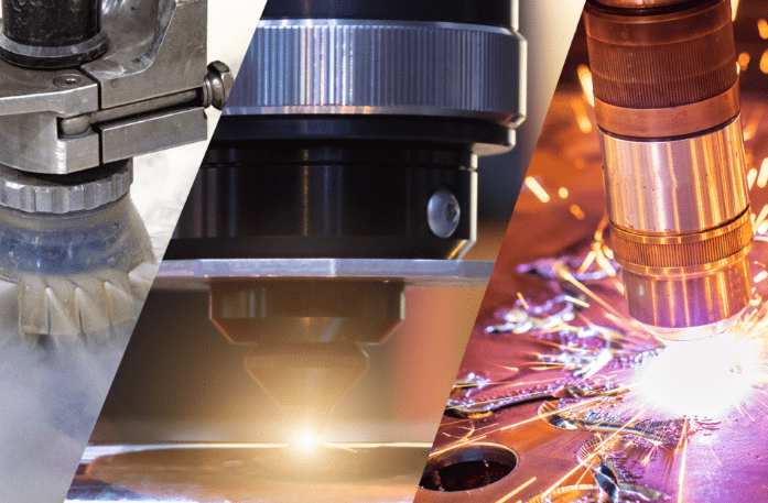
Four primary technologies dominate custom steel sheet cutting today: laser cutting, plasma cutting, waterjet cutting, and mechanical shearing. Each operates on fundamentally different principles, producing distinct results in edge quality, heat effects, and achievable tolerances. Let's examine how each actually works.
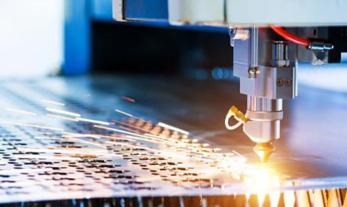
How Laser Cutting Achieves Precision Through Focused Light
Ever wondered how light can slice through steel? A laser cutter concentrates photons into an incredibly narrow beam—sometimes as thin as 0.1mm—that delivers enough energy to melt or vaporize metal almost instantaneously. This focused beam follows computer-controlled paths with remarkable accuracy, achieving tolerances as tight as ±0.13mm on thin materials.
The process works through three mechanisms depending on material and thickness:
- Fusion cutting: The laser melts the metal while assist gas (typically nitrogen) blows molten material away from the kerf—the narrow channel created by cutting
- Flame cutting: Oxygen reacts with heated steel, creating an exothermic reaction that accelerates cutting speed on carbon steels
- Vaporization cutting: Extremely high energy density instantly vaporizes material, ideal for very thin sheets
According to AAA Metals, laser cutting offers exceptional precision and accuracy while minimizing material contamination—making it the go-to choice for electronics, medical devices, and precision parts manufacturing. However, reflective metals like copper and brass can pose challenges since they may redirect laser energy back toward the equipment.
The kerf width in laser cutting remains remarkably consistent, typically between 0.1mm and 0.4mm depending on material thickness. This narrow kerf means less material waste and the ability to nest parts closer together on your sheet.
Plasma vs Waterjet Technology Explained
While laser cutting dominates thin-sheet precision work, plasma and waterjet technologies each carve out distinct advantages for specific applications.
Plasma Cutting: Electrical Arc Power
Plasma cutting creates a superheated channel of ionized gas—plasma—that reaches temperatures exceeding 20,000°C. Here's what happens: an electrical arc forms between the torch electrode and your workpiece, ionizing gas (typically air, nitrogen, or argon) flowing through the nozzle. This plasma jet melts the metal while the high-velocity gas stream blows molten material through the cut.
As noted in testing by Wurth Machinery, plasma cutting proves particularly efficient for thick conductive metals—cutting 1-inch steel approximately 3-4 times faster than waterjet, with roughly half the operating cost per foot. The trade-off? Larger heat-affected zones and wider kerf widths compared to laser cutting.
Waterjet Cutting: Cold Precision
Waterjet technology takes an entirely different approach—no heat involved. Ultra-high-pressure water (up to 90,000 PSI) streams through a tiny orifice, often mixed with abrasive particles like garnet. This abrasive waterjet erodes material rather than melting it, producing cuts without any heat-affected zone.
This cold cutting characteristic makes waterjet invaluable when thermal distortion must be avoided. The waterjet market is projected to reach over $2.39 billion by 2034, reflecting growing demand for heat-free cutting in aerospace, automotive, and precision manufacturing applications.
Mechanical Shearing: Direct Force
Shearing operates on the simplest principle: a moving upper blade descends against a stationary lower blade, with both slightly offset. The pressure deforms the metal until it fractures along the cut line. Unlike thermal methods, shearing generates virtually no waste chips and works quickly for straight cuts.
This method excels for high-volume production of simple shapes but cannot create curved or intricate geometries. It's best suited for flat sheets rather than hollow materials that might deform under pressure.
Cutting Method Comparison at a Glance
When evaluating these technologies, several factors determine which method matches your project requirements. Just as you might reference a drill bit size chart when selecting tooling, this comparison helps you select the appropriate cutting technology:
| Factor | Laser Cutting | Plasma Cutting | Waterjet Cutting | Mechanical Shearing |
|---|---|---|---|---|
| Precision Tolerance | ±0.13mm typical | ±0.5mm to ±1.5mm | ±0.13mm to ±0.25mm | ±0.25mm to ±0.5mm |
| Thickness Capacity (Steel) | Up to 25mm | Up to 150mm+ | Up to 150mm (6") | Up to 25mm typical |
| Edge Quality | Excellent, minimal finishing | Good, may need grinding | Excellent, smooth matte finish | Good for straight cuts |
| Heat-Affected Zone | Small (0.1-0.5mm) | Large (3-6mm) | None | None |
| Kerf Width | 0.1-0.4mm | 1.5-5mm | 0.5-1.5mm | Minimal material loss |
| Best Applications | Thin sheets, intricate details, tight tolerances | Thick steel, structural fabrication, speed priority | Heat-sensitive materials, mixed materials, thick precision cuts | High-volume straight cuts, sheet preparation |
| Relative Cost | Medium-High | Low-Medium | High | Low |
Understanding the difference between cutting technologies is similar to understanding mig vs tig welding—each method has optimal applications, and matching the right technique to your material and requirements determines success. Laser cutting and waterjet deliver precision comparable to spot welding positioning accuracy, while plasma offers speed advantages for heavy structural work.
The technology you choose directly impacts not just cut quality, but also downstream operations. Parts requiring precise assembly benefit from laser or waterjet's tight tolerances, while structural components destined for spot welding or heavy fabrication may tolerate plasma's wider margins.
With cutting technologies understood, the next critical decision involves your material itself—because steel grade selection dramatically affects which method will deliver optimal results.
Steel Material Selection and Cutting Compatibility
You've selected your cutting technology—but here's where many projects go wrong. The steel grade you choose dramatically affects which cutting method delivers optimal results. Different types of metal respond uniquely to heat, pressure, and abrasion, meaning a method that works beautifully on carbon steel might produce poor results on stainless.
Understanding this relationship between material and method prevents costly mistakes and ensures your finished parts meet specifications.
Matching Steel Grades to Cutting Methods
Each steel grade brings distinct properties that influence cutting behavior. Here's what you need to know about the most common options:
Carbon Steel (Mild Steel)
- Most economical and widely available option for fabrication projects
- Excellent compatibility with all cutting methods—laser, plasma, waterjet, and shearing
- Lower melting point allows faster laser and plasma cutting speeds
- Oxidizes when exposed to moisture, requiring protective coatings or paint after cutting
- Best for structural applications, frames, brackets, and general fabrication
304 Stainless Steel Sheet
- Most common stainless grade, offering good corrosion resistance and formability
- Higher thermal conductivity requires adjusted laser parameters to prevent edge discoloration
- Produces excellent results with waterjet cutting—no heat-affected zone concerns
- Work hardens during cutting, which can affect subsequent machining operations
- Ideal for food processing equipment, architectural elements, and kitchen applications
316 Stainless Steel
- Superior corrosion resistance compared to 304, especially against chlorides and marine environments
- Contains molybdenum, making it slightly more challenging to cut than 304 grades
- Laser cutting works well but requires nitrogen assist gas to prevent oxidation
- Waterjet cutting eliminates any heat-related concerns with this premium material
- Best for marine applications, chemical processing, and medical devices
When comparing 304 vs 316 stainless steel for your project, the decision often comes down to environment. If your parts will encounter saltwater, harsh chemicals, or require medical-grade corrosion resistance, 316 justifies its higher cost. For general-purpose applications, 304 delivers excellent performance at lower material expense.
Galvanized Steel and Coated Materials
- Zinc coating provides corrosion protection but creates cutting challenges
- Laser cutting vaporizes zinc, potentially producing hazardous fumes requiring proper ventilation
- Plasma cutting handles galvanized sheet metal effectively but may damage coating near edges
- Waterjet cutting preserves coating integrity better than thermal methods
- Shearing works well for straight cuts without affecting coating away from the cut edge
AR500 (Abrasion Resistant Steel)
- Hardened steel designed for extreme wear resistance—commonly used in shooting targets and wear plates
- High hardness (approximately 500 Brinell) makes cutting more demanding
- Plasma cutting works effectively but produces larger heat-affected zones that may reduce edge hardness
- Waterjet cutting maintains material hardness throughout—no thermal effects
- Laser cutting possible on thinner AR500 but requires slower speeds and higher power
A common question when selecting stainless grades: is stainless steel magnetic? The answer varies by type. Austenitic grades like 304 and 316 are generally non-magnetic in their annealed state, though cold working can induce slight magnetism. This matters for applications requiring non-magnetic properties or when using magnetic fixturing during fabrication.
When to Choose Stainless Over Carbon Steel
The stainless-versus-carbon decision impacts both your cutting approach and project success. Consider stainless steel sheet when:
- Corrosion resistance is essential—outdoor exposure, moisture contact, or chemical environments
- Aesthetic appearance matters—stainless maintains its finish without painting
- Food-safe or medical applications require non-reactive surfaces
- Long-term maintenance costs outweigh higher initial material investment
Carbon steel makes more sense when:
- Parts will be painted, powder coated, or otherwise protected from corrosion
- Budget constraints prioritize material cost over maintenance considerations
- Structural strength matters more than surface appearance
- Faster cutting speeds and lower fabrication costs are project priorities
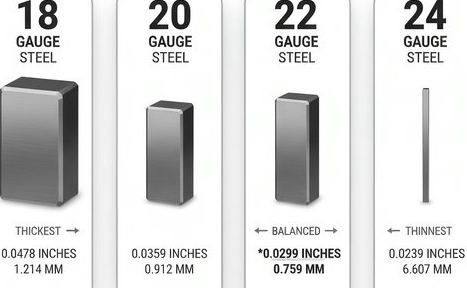
Understanding Gauge Measurements for Steel Sheets
Material thickness directly determines which cutting methods are viable and cost-effective. The gauge system—while counterintuitive—remains the standard for specifying steel sheet thickness.
Here's the key principle: lower gauge numbers mean thicker material. According to Qualitest's steel gauge reference, this inverse relationship often confuses first-time buyers.
| Gauge | Thickness (inches) | Thickness (mm) | Common Applications |
|---|---|---|---|
| 10 gauge | 0.1345" | 3.416 mm | Industrial flooring, trailers, heavy machinery |
| 11 gauge | 0.1196" | 3.038 mm | Truck beds, construction panels, weight-bearing walls |
| 12 gauge | 0.1046" | 2.657 mm | Security doors, brackets, structural components |
| 14 gauge | 0.0747" | 1.897 mm | Steel studs, fencing, cabinets, enclosures |
| 16 gauge | 0.0598" | 1.519 mm | HVAC systems, metal cabinets, automotive bodywork |
This thickness range—from 10 gauge at 3.4mm down to 16 gauge at 1.5mm—represents the sweet spot where laser cutting excels. Thinner gauges cut faster with less power, while 10-11 gauge material may require higher wattage lasers or alternative methods like plasma for efficient processing.
With your steel grade selected and thickness understood, the next step involves matching these specifications to cutting method capabilities—ensuring your chosen technology can handle your specific material requirements.
Thickness Capabilities and Method Limitations
Now that you understand steel grades and gauge measurements, here's the critical question: can your chosen cutting method actually handle your material thickness? Each technology has distinct sweet spots where it performs optimally—and limitations where quality or efficiency suffers dramatically.
Getting this match wrong means either poor edge quality, excessive costs, or outright cutting failures. Let's break down exactly what each method can handle.
Thickness Limits by Cutting Technology
Every cutting technology has an optimal operating range. Push beyond these limits, and you'll encounter slower speeds, rougher edges, or equipment that simply cannot complete the cut.
Laser Cutting Thickness Capabilities
Laser cutting dominates thin-sheet precision work. According to KF Laser's thickness chart, here's what different power levels can handle for steel:
- Thin sheets (0.5mm – 3mm): 1000W to 2000W lasers cut easily with minimal heat-affected zones
- Medium plates (4mm – 12mm): 2000W to 4000W lasers maintain precision through thicker material
- Thick plates (13mm – 20mm): 4000W to 6000W lasers required for deeper penetration
For stainless steel, similar power requirements apply, though cutting speeds decrease slightly due to the material's higher thermal conductivity. Beyond approximately 25mm, laser cutting becomes impractical for most applications—plasma or waterjet takes over.
Plasma Cutting Thickness Range
Where laser cutting ends, plasma truly shines. As noted by StarLab CNC, plasma excels on materials from 0.018" to 2" thick, with some systems capable of cutting beyond 6 inches on mild steel.
The optimal quality range falls between 1/4 inch (approximately 6mm) up to 1.5 inches (38mm). Within this range, you'll achieve:
- Clean cut surfaces requiring minimal secondary finishing
- Cutting speeds exceeding 100 inches per minute on 1/2" material
- Consistent edge quality with manageable dross
Below 1/4 inch, plasma can cut but laser typically delivers better precision. Above 1.5 inches, edge quality begins degrading, though the cut remains functional for structural applications.
Waterjet Thickness Capacity
Waterjet technology handles the broadest thickness range without quality degradation from heat. Practical limits extend to 6-8 inches of steel, though cutting time increases substantially at extreme thicknesses. The ESAB reference guide notes that waterjet stream divergence becomes problematic beyond this range.
For precision work, waterjet maintains ±0.13mm tolerances across its entire thickness range—something thermal methods cannot match on heavy plate.
Choosing Methods for Thin Sheet vs Heavy Plate
Your material thickness fundamentally determines the optimal cutting approach. Here's practical guidance for common gauge sizes:
For 16 gauge steel thickness (1.5mm)—laser cutting delivers unmatched precision and speed. The thin material cuts quickly with minimal heat input, producing edges that often require no secondary finishing. Plasma works but offers no advantage at this thickness.
For 14 gauge steel thickness (1.9mm)—laser remains the preferred choice. You'll achieve tolerances within ±0.13mm and excellent edge quality. This thickness represents the sweet spot for fiber laser efficiency.
For 12 gauge steel thickness (2.7mm)—laser cutting still excels, though slightly higher power settings become necessary. Both laser and plasma can handle this gauge effectively, with laser preferred for precision parts and plasma for high-volume structural work.
For 11 gauge steel thickness (3.0mm)—this marks the transition zone. Laser cutting remains viable with 2000W+ systems, while plasma starts offering competitive speed advantages. Your choice depends on whether precision or throughput matters more.
For heavy plate (12mm and above)—plasma or waterjet becomes necessary. Laser cutting slows dramatically and edge quality suffers. Plasma offers speed advantages, while waterjet provides precision without heat-affected zones.
Thickness and Edge Quality Relationships
Edge quality expectations shift significantly across thickness ranges. The table below shows what each method delivers for different steel types and thicknesses:
| Thickness Range | Steel Type | Laser Cutting | Plasma Cutting | Waterjet Cutting |
|---|---|---|---|---|
| 0.5mm – 3mm | Carbon Steel | Excellent edges, minimal HAZ | Good but overkill | Excellent, no HAZ |
| 0.5mm – 3mm | Stainless Steel | Excellent with nitrogen assist | Acceptable | Excellent, preserves finish |
| 4mm – 8mm | Carbon Steel | Very good, slight HAZ | Good, moderate dross | Excellent |
| 4mm – 8mm | Stainless Steel | Good, requires power increase | Good with proper gas | Excellent |
| 10mm – 20mm | Carbon Steel | Acceptable with high power | Good, cost-effective | Very good |
| 10mm – 20mm | Stainless Steel | Marginal, slow speeds | Good | Excellent |
| 25mm+ | Any Steel | Not recommended | Good for structural | Good, slow speed |
Heat-Affected Zone Considerations
Heat-affected zones (HAZ) deserve special attention because they can alter your steel's properties near cut edges. The HAZ represents material that didn't melt but experienced enough heat to change its microstructure.
On thin gauge material (16 gauge and thinner), laser cutting produces negligible HAZ—typically less than 0.2mm. As thickness increases toward 10-12mm, the HAZ expands to 0.3-0.5mm even with optimized parameters.
Plasma cutting generates substantially larger heat-affected zones—typically 3-6mm depending on amperage and cutting speed. For structural applications, this rarely matters. For precision assemblies requiring tight tolerances throughout, it can be problematic.
Waterjet cutting eliminates HAZ entirely. When working with AR500 or other hardened steels where edge hardness matters, waterjet preserves material properties right to the cut edge.
Understanding these thickness-method relationships helps you specify the right approach from the start. But even perfect method selection means nothing without properly prepared design files—the subject of our next section.
Preparing Your Design Files and Specifications
You've selected your cutting method and steel grade—now comes the step where many projects stumble. Poorly prepared design files cause delays, miscommunication, and costly rework. Yet most fabrication guides skip this entirely, leaving you guessing about file formats, dimension notation, and tolerance specifications.
Getting your custom cut steel sheet order right the first time requires understanding exactly what cutting services need from your design files. Let's walk through the complete preparation process.
Design File Formats That Cutting Services Accept
Not all file formats work equally well for sheet metal fabrication. According to Bendtech Group's laser cutting guidelines, vector files deliver the best results because they contain precise mathematical definitions of your cut paths rather than pixel-based approximations.
Here are the formats most cutting services prefer:
- DXF (Drawing Exchange Format): The industry standard for CAD-to-cutting machine communication. Nearly universal compatibility across all fabrication equipment.
- AI (Adobe Illustrator): Excellent for designs created in graphics software. Ensure all text is converted to outlines before submission.
- SVG (Scalable Vector Graphics): Works well for web-originated designs. Verify dimensions are accurate after conversion.
- PDF (Vector-based): Acceptable when exported from CAD software with vector data preserved. Avoid PDF files created from raster images.
Critical file preparation requirements include:
- Set all cut paths as hairline lines with approximately 0.1mm stroke width
- Use clear layer separation or color coding to distinguish cutting from engraving operations
- Maintain consistent units throughout—millimeters preferred for precision work
- Remove duplicate lines, overlapping paths, or tiny stray segments that slow cutting
If you've converted from a raster file (JPG, PNG, or similar), verify all dimensions carefully. As SendCutSend's guidelines recommend, printing your design at 100% scale helps confirm dimensions and scale match your intentions.
Avoiding Costly Specification Errors
Custom cut sheet metal projects fail most often due to preventable specification mistakes. Understanding these common errors—and how to avoid them—saves both time and money.
Tolerance Specification Mistakes
Specifying tolerances tighter than your cutting method can achieve creates immediate problems. Realistic tolerance expectations based on cutting technology:
- Laser cutting: ±0.1mm to ±0.13mm achievable on thin materials
- Plasma cutting: ±0.5mm to ±1.5mm depending on thickness
- Waterjet cutting: ±0.13mm to ±0.25mm typical range
When tolerances aren't explicitly specified, fabricators apply their standard shop tolerances—which may not match your assembly requirements. Always communicate critical dimensions clearly.
Geometry and Feature Errors
According to MetalsCut4U's fabrication guide, these sheet metal fabrication mistakes occur frequently:
- Holes too small: Minimum hole diameter should equal material thickness for steel 3mm or thinner. Thicker materials require larger ratios.
- Features too close together: Allow minimum spacing equal to material thickness between cut features to prevent heat distortion.
- Sharp internal corners: Laser beams create natural radii of 0.05-0.2mm. Design radiused corners instead of specifying impossible sharp angles.
- Text too thin: Use sans-serif fonts with minimum 3mm height and strokes no thinner than 0.5mm for legible cut text.
Kerf Allowance Oversight
The kerf—material removed during cutting—affects final dimensions. Laser cutting removes 0.1-0.3mm of material width. Failing to account for this in your design means parts come out slightly undersized or slots fit too loosely.
Your Custom Cutting Order Checklist
Before submitting your order for sheet metal cut to size, run through this step-by-step verification process:
- Verify file format compatibility: Confirm your file is in DXF, AI, SVG, or vector PDF format. Convert any raster elements to vector paths.
- Check dimension accuracy: Print at 100% scale or use CAD measurement tools to verify all critical dimensions match your requirements.
- Convert all text to outlines: Editable text causes errors. In Illustrator, use "Create Outlines"; in CAD software, use "Explode" or "Expand" commands.
- Clean geometry: Remove duplicate lines, overlapping paths, and stray points. These cause cutting hesitation and rough edges.
- Verify hole and feature minimums: Confirm all holes meet minimum diameter requirements for your material thickness.
- Account for kerf: Adjust dimensions for the 0.1-0.3mm material removal if tight fits are critical.
- Specify tolerances clearly: Note which dimensions are critical and what tolerance range is acceptable.
- Separate retained cutouts: Internal pieces you want to keep must be submitted as separate designs or include bridging tabs.
- Include material specifications: Clearly state steel grade, thickness (gauge or millimeters), and any finish requirements.
- Document special requirements: Note grain direction preferences, edge finish expectations, or secondary operation needs.
Communicating Special Requirements
Beyond standard dimensions and tolerances, custom metal shapes often require additional specifications that affect fabrication approach:
- Grain direction: If your parts will be bent, specify whether bends should run parallel or perpendicular to grain. Bending across the grain provides more flexibility and reduces cracking risk.
- Edge quality expectations: State whether edges require grinding, deburring, or are acceptable as-cut.
- Surface protection: Indicate if protective film should remain during cutting or if bare material is acceptable.
- Quantity and nesting preferences: For multiple parts, note if they can be nested together or require individual handling.
Proper file preparation transforms your custom sheet metal project from a source of potential problems into a smooth fabrication process. With your design files ready, the next consideration becomes understanding what your order will cost—and which factors most significantly impact pricing.
Cost Factors and Pricing Considerations
Your design files are ready—but how much will this custom metal cutting project actually cost? Unlike standard catalog parts with fixed prices, custom steel fabrication involves multiple variables that combine to determine your final quote. Understanding these factors helps you budget accurately and identify opportunities to reduce expenses without sacrificing quality.
Steel fabricators calculate pricing based on several interconnected elements. Some you control directly through design decisions. Others depend on market conditions and your project's specific requirements. Let's examine what drives costs so you can make informed choices.
What Drives Custom Cutting Costs
When steel fabricators prepare quotes, they evaluate your project across multiple dimensions. According to Metaltech's fabrication cost guide, these factors combine to determine your final price—listed here in order of typical impact on total project cost:
- Raw Material Costs (Often Largest Factor): Steel prices fluctuate with market conditions. The grade you select—carbon steel, 304 stainless, 316 stainless, or specialty alloys—dramatically affects material expense. Sheet thickness and total square footage multiply this base cost.
- Labor and Machine Time: The majority of a project's cost comes from skilled labor. Engineers assist with design review, fabricators operate cutting equipment, and quality inspectors verify results. Machine time—whether laser, plasma, or waterjet—adds per-hour operational costs.
- Cutting Method Selected: Different technologies carry different operational expenses. According to Xometry's comparison data, laser cutting typically averages around $20/hour operationally, while plasma cutting runs approximately $15/hour. Waterjet cutting generally costs more due to consumable abrasive expenses.
- Design Complexity: Simple rectangular shapes cost less than intricate geometries. Every cut, curve, and internal feature adds time. Tight tolerances requiring slower cutting speeds increase machine time. Complex part geometries may need specialized tooling or programming.
- Order Quantity: Single prototypes cost more per part than production runs. Machine setup only happens once regardless of quantity—spreading that fixed cost across more parts reduces individual piece pricing.
- Secondary Operations: Finishing processes like deburring, grinding, powder coating services, or assembly add labor and materials beyond the cutting operation itself.
Material costs deserve special attention because they can shift unexpectedly. Steel prices experienced dramatic volatility in recent years—hot-rolled steel reached $1,955 per ton in September 2021 before decreasing to more stable levels. When requesting quotes, understand that material pricing reflects current market conditions and may differ from estimates received weeks earlier.
Quantity Breaks and Volume Pricing
Sounds complex? The quantity-cost relationship is actually straightforward once you understand the underlying mechanics.
When you order larger volumes of custom cut components, the per-piece price drops for several reasons:
- Setup cost distribution: Programming the cutting machine, loading material, and configuring parameters happens once per job. Whether you cut 10 parts or 1,000, setup time remains similar—but costs spread across more pieces.
- Material efficiency: Larger orders allow better nesting optimization. Steel fabricators can arrange more parts on each sheet, reducing waste percentage and material costs per piece.
- Production flow: Once machines are running your job, maintaining continuous operation costs less than stopping, switching jobs, and restarting.
For single prototypes or small quantities, expect higher per-unit pricing. This doesn't mean metal fab shops are overcharging—it reflects the reality that setup costs represent a larger portion of small orders. If your project allows, consider ordering slightly larger quantities to capture volume pricing benefits.
Design Optimization Reduces Costs
Here's where your decisions directly impact project expense. Smart design choices can reduce fabrication costs by 15-30% without compromising part functionality.
Efficient Nesting Matters
Nesting—how parts arrange on raw sheets—significantly affects material utilization. According to Consac's optimization research, material costs typically represent 50-75% of total sheet metal production expenses. Even a 5% improvement in material efficiency can save thousands of dollars annually on recurring orders.
Modern nesting software evaluates thousands of arrangements in seconds, finding efficiencies impossible to calculate manually. Fabrication shops report 15-30% material savings after implementing automated nesting solutions.
Design Choices That Reduce Costs
- Use standard sheet sizes: Custom material dimensions cost more than standard stock sizes. Design parts to nest efficiently on commonly available sheets.
- Simplify geometries: Only include design elements—beveled edges, internal cutouts, complex curves—when functionally necessary. Simple angles and consistent features speed fabrication.
- Reserve tight tolerances: Apply precision tolerances only to surfaces critical for function. Specifying tight tolerances everywhere increases costs without adding value.
- Allow part rotation: Permitting your parts to rotate during nesting (rather than requiring fixed orientation) enables better material utilization.
- Consider common-line cutting: When possible, design adjacent parts to share cutting lines. This reduces both material waste and cutting time.
Understanding Your Quote
When you receive a quote from steel fabricators, look for line-item breakdowns showing material costs, cutting/labor charges, and finishing operations separately. This transparency helps you identify where costs concentrate and where optimization might provide savings.
If a quote seems high, ask the fabricator which factors are driving the price. Often, small design modifications—slightly larger internal radii, relaxed tolerances on non-critical features, or adjusted material thickness—can reduce costs meaningfully without affecting part performance.
Remember that the lowest quote doesn't always represent the best value. Quality issues, rework costs, and project delays from inexperienced fabricators often exceed initial savings from choosing the cheapest option.
With cost factors understood, you can make informed trade-offs between budget and requirements. But cutting is often just the beginning—the next section explores secondary operations and finishing options that transform raw cut parts into finished components.
Secondary Operations and Finishing Options
Your steel parts are cut to specification—but they're rarely ready for immediate use. Most custom steel projects require additional processing before components can serve their intended purpose. These secondary operations transform raw cut pieces into functional, durable, finished parts.
Planning for these operations during your initial design phase—rather than as afterthoughts—improves outcomes and often reduces overall project costs. When you understand what's possible, you can design smarter from the start.
Post-Cutting Operations That Add Value
According to D+M Metal Products, secondary processes refer to finishing, treatment, and refinement techniques applied after primary fabrication steps are complete. These processes enhance strength, environmental resistance, aesthetic appeal, and overall performance.
Secondary operations fall into three main categories—each addressing different project requirements:
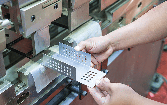
Forming Operations
- Bending: Transforms flat cut sheets into three-dimensional shapes using press brakes or roll forming equipment. Plan bend locations during design to ensure proper grain orientation and minimum bend radii for your material thickness.
- Rolling: Creates curved surfaces and cylindrical shapes from flat stock. Radius limitations depend on material thickness and grade.
- Stamping and pressing: Adds features like embossed logos, reinforcing ribs, or locating dimples through controlled deformation.
Joining Operations
- Welding: Permanently joins steel components through fusion. MIG and TIG welding work well for most steel fabrication, while spot welding creates discrete connection points ideal for sheet assemblies. Note that welding aluminum requires different techniques and filler materials than steel joining.
- Hardware insertion: Pre-installs fasteners, gaskets, or brackets during fabrication rather than requiring field assembly.
- Mechanical fastening: Riveting, clinching, or self-piercing connections provide alternatives when welding isn't suitable.
Surface Preparation
- Deburring and edge finishing: Removes sharp burrs left after cutting through grinding, tumbling, or abrasive brushing. This creates parts that are smooth and safe to handle.
- Polishing and buffing: Removes surface imperfections and increases reflectivity—especially valuable for food processing and medical applications where smooth surfaces matter.
- Heat treatment: Annealing, quenching, or tempering alters metal properties to improve strength, hardness, or flexibility for demanding applications.
Surface Finishing Options for Steel Parts
Surface finishes protect your steel components from corrosion and wear while enhancing visual appeal. Your choice depends on operating environment, aesthetic requirements, and budget.
Coating and Finishing Options
- Powder coat: A dry application process where electrostatically charged powder adheres to grounded metal parts, then cures in an oven to form a durable, uniform layer. According to Gabrian's finishing comparison, powder coating is environmentally friendly—no solvents are used—and produces very durable, attractive finishes in a wide variety of colors and textures.
- E-coating: Electrocoating applies paint through electrical current, providing excellent coverage on complex geometries and recessed areas.
- Plating: Applies materials like zinc, nickel, or chrome for corrosion protection or visual appeal. Galvanizing (zinc plating) offers economical rust protection for carbon steel.
- Painting: Traditional liquid coatings remain cost-effective for many applications, though durability typically falls below powder coating.
Understanding Anodizing for Aluminum Components
While this article focuses on steel, many projects combine steel cutting with aluminum elements. Anodized aluminum undergoes an electrochemical process that thickens the natural oxide layer, creating enhanced corrosion and wear resistance. Unlike coatings applied to steel, anodizing becomes part of the aluminum substrate rather than sitting on top of it.
Anodizing works only on aluminum and titanium—not steel. For mixed-material projects, coordinate finishing specifications for each material type separately.
Planning Secondary Operations During Design
Imagine designing a part, having it cut, then discovering the bend sequence is impossible because features interfere with tooling. This scenario happens when secondary operations aren't considered during initial design.
Smart planning involves:
- Bend allowance calculations: Account for material stretch and compression when flat patterns transform into bent shapes. Incorrect allowances mean parts don't fit during assembly.
- Weld access: Ensure welders can reach joint locations with proper torch angles. Cramped geometries increase defect rates and labor time.
- Coating considerations: Powder coat adds 2-4 mils of thickness. Account for this on mating surfaces and threaded features.
- Assembly sequence: Design for logical build order. Some operations must happen before others—planning this flow prevents rework.
Integrated Manufacturing Advantages
Working with fabricators who offer integrated services—cutting through finished assembly under one roof—streamlines production significantly. As noted by Integrated Metal Products, comprehensive capabilities including processing, machining, fabrication, welding, coatings, and assembly eliminate the coordination burden of managing multiple vendors.
Benefits of integrated manufacturing include:
- Reduced lead times: Parts move directly between operations without shipping delays between facilities
- Quality consistency: Single-source responsibility for all operations simplifies accountability
- Design feedback: Fabricators who handle all operations can suggest improvements that benefit multiple production stages
- Lower total cost: Eliminating markup, shipping, and coordination between multiple vendors often reduces overall project expense
When secondary operations require outsourcing—powder coating to trusted vendors, for example—integrated fabricators often maintain established relationships that ensure quality and timing. You receive finished products without having to shop around and send parts to multiple facilities.
Understanding these post-cutting possibilities helps you design complete parts rather than just cut shapes. With your finishing requirements defined, the final step involves selecting a fabrication partner capable of delivering quality results—the focus of our next section.
Choosing a Custom Steel Cutting Partner
You've defined your material, prepared your design files, and understand what secondary operations you need. Now comes a decision that determines whether your project succeeds or stumbles: selecting the right fabrication partner. When you search for sheet metal fabrication near me or metal fabricators near me, dozens of options appear—but how do you distinguish capable partners from shops that will cause headaches?
The difference between a smooth project and a frustrating experience often comes down to factors that aren't immediately visible. Quality certifications, technical support capabilities, and communication practices matter as much as cutting equipment. Let's examine what separates reliable partners from risky choices.
Quality Certifications That Matter for Steel Cutting
Certifications aren't just wall decorations—they represent verified systems for producing consistent, reliable results. When evaluating fabrication shops near me, understanding what certifications mean helps you assess actual capabilities rather than marketing claims.
ISO 9001: The Foundation
ISO 9001 certification indicates a company follows documented quality management systems. According to OGS Industries, this standard centers on customer satisfaction through monitored and measured processes that maximize productivity and deliver consistent outcomes.
For general fabrication work, ISO 9001 provides reasonable quality assurance. However, demanding applications require more rigorous standards.
IATF 16949: Automotive-Grade Quality
If your steel cutting project involves automotive components—or any application requiring exceptional precision and reliability—IATF 16949 certification represents the gold standard. This certification builds upon ISO 9001 requirements while adding specific provisions for:
- Lean manufacturing practices: Streamlined processes that eliminate waste and improve efficiency
- Defect prevention systems: Proactive measures that catch problems before they reach customers
- Reduced product variation: Reviewed manufacturing processes ensuring components consistently meet specifications
- Supply chain reliability: Internationally recognized benchmarks for sourcing and supplier management
As OGS Industries explains, IATF 16949-certified manufacturers have proven their metal fabrication, production, welding, and finishing processes meet stringent product safety requirements while minimizing defects. For chassis, suspension, and structural components where failure isn't an option, this certification provides meaningful assurance.
Manufacturers like Shaoyi (Ningbo) Metal Technology maintain IATF 16949 certification specifically because automotive and precision manufacturing customers require verified quality systems. When evaluating partners for demanding applications, this certification should be a baseline requirement—not an optional bonus.
Evaluating Turnaround and Support Capabilities
Beyond certifications, practical capabilities determine whether a fabricator can actually deliver your project successfully. TMCO's fabrication partner guide identifies several critical factors to evaluate:
In-House Capabilities Matter
Not all fabrication shops offer comprehensive services. Some only cut metal, outsourcing machining, finishing, or assembly—creating delays, communication gaps, and quality inconsistencies. Full-service facilities streamline the entire process under one roof, providing tighter control over production and faster turnaround times.
Key capabilities to verify include:
- Multiple cutting technologies (laser, plasma, waterjet) for material flexibility
- CNC machining and precision forming capabilities
- Welding services (TIG, MIG, robotic options)
- Finishing operations (powder coating, plating, assembly)
- Quality inspection equipment and documented processes
Engineering and DFM Support
Successful fabrication doesn't begin at the cutting machine—it begins with engineering review. According to Design for Manufacturability (DFM) best practices, early collaboration between designers and manufacturers identifies potential issues before they become expensive problems.
DFM support typically reduces total project costs by 15-30% through multiple mechanisms: decreased material waste, optimized cutting patterns, simplified geometries, and appropriate tolerance specifications. Look for partners offering:
- CAD/CAM support and file review
- Prototype testing capabilities
- Material and design recommendations
- Engineering consultation for complex assemblies
Partners like Shaoyi provide comprehensive DFM support that helps optimize designs for manufacturing—catching issues during design review rather than discovering them during production.
Response Time and Quote Turnaround
How quickly a fabricator responds to inquiries reveals their operational efficiency. Fast quote turnaround—some manufacturers offer 12-hour response times—indicates streamlined processes and customer focus. Slow responses often predict slow production.
For projects requiring speed, look for rapid prototyping capabilities. Some manufacturers deliver prototype parts within 5 days, allowing you to validate designs before committing to production volumes. This capability proves invaluable when development timelines are tight.
Key Evaluation Criteria Checklist
When comparing potential fabrication partners, systematically evaluate these factors:
- Experience and industry knowledge: Years in business, familiarity with your application, and relevant case studies or references
- Quality certifications: ISO 9001 minimum; IATF 16949 for automotive or precision applications
- In-house capabilities: Comprehensive services versus outsourced operations
- Engineering support: DFM review, CAD assistance, and design optimization guidance
- Communication practices: Quote responsiveness, project updates, and transparent timelines
- Scalability: Ability to handle prototypes through production volumes without quality degradation
- Inspection and testing: First-article inspection, in-process checks, and final verification procedures
- Lead time reliability: Track record for on-time delivery and realistic scheduling
Beyond Cutting: What Full-Service Partners Offer
While searching for sheet metal near me might lead you to shops focused solely on cutting, the best partners offer integrated capabilities from design through finished assembly. This matters because coordination between multiple vendors adds complexity, cost, and opportunities for miscommunication.
Consider whether your project involves custom metal signs, architectural elements, or precision components—each application benefits from partners who understand the complete workflow. A fabricator experienced in your industry anticipates challenges specific to your application and provides relevant guidance.
The right partner doesn't just build parts—they support your goals, improve your product, and help position your project for success. With evaluation criteria defined, you're ready to make your final decision about cutting methods and partners.
Making Your Custom Steel Cutting Decision
You've explored cutting technologies, steel grades, thickness limitations, file preparation, cost factors, and partner selection criteria. Now it's time to synthesize everything into a clear decision framework. Knowing how to cut steel sheet effectively means matching your specific project characteristics to the right method—and the right manufacturing partner.
Whether you're working with stainless steel sheet metal for food processing equipment, aluminum sheet metal for lightweight enclosures, or heavy steel plates for structural applications, this final section helps you move from research to action.
Matching Your Project to the Right Cutting Approach
Every project has unique requirements that point toward specific cutting methods. Rather than defaulting to whatever a fabricator recommends, use this decision matrix to identify your optimal approach based on your actual needs:
| Project Characteristic | Recommended Method | Why This Works |
|---|---|---|
| Thin sheets (under 6mm), intricate details required | Laser Cutting | Achieves ±0.13mm tolerances with minimal heat-affected zone |
| Thick steel plates (12mm+), structural applications | Plasma Cutting | Fast cutting speeds, cost-effective for heavy material |
| Heat-sensitive materials, hardened steels like AR500 | Waterjet Cutting | No thermal effects, preserves material properties throughout |
| High-volume straight cuts, simple geometries | Mechanical Shearing | Fastest method for basic shapes, lowest per-piece cost |
| Stainless steel sheets requiring pristine edges | Laser (with nitrogen) or Waterjet | Prevents oxidation discoloration on cut surfaces |
| Mixed materials in single project | Waterjet Cutting | Handles steel, aluminum, composites without equipment changes |
| Prototype parts with fast turnaround needs | Laser Cutting | Quick setup, minimal material waste for small quantities |
| Custom steel plate for machinery, heavy equipment | Plasma or Waterjet | Handles thick materials efficiently with acceptable tolerances |
When your project spans multiple categories—perhaps requiring both precision tolerances and thick metal sheets—you may need multi-process cutting. Many fabricators combine methods strategically, using laser for intricate features and plasma for heavy structural cuts on the same assembly.
Next Steps for Your Custom Steel Project
Ready to move forward? Follow this action sequence to transform your project from concept to completed parts:
- Finalize your material specification: Confirm steel grade, thickness, and any special requirements based on your application environment.
- Prepare your design files: Export clean DXF or vector files with proper tolerancing and dimensioning. Remove duplicate lines and convert all text to outlines.
- Request quotes from qualified partners: Submit your files to 2-3 fabricators with relevant certifications. For automotive or precision needs, prioritize IATF 16949-certified manufacturers.
- Evaluate quotes holistically: Compare not just price, but capabilities, lead times, DFM support, and quality systems. The lowest quote rarely represents best value.
- Start with prototypes when possible: Validate fit and function before committing to production volumes. Manufacturers offering 5-day rapid prototyping can accelerate this validation significantly.
- Plan secondary operations upfront: Communicate bending, welding, and finishing requirements during quoting to receive accurate total project costs.
For readers with automotive or precision manufacturing needs, specialized manufacturers with rapid prototyping capabilities can accelerate project timelines dramatically—from concept to production-ready parts in days rather than weeks. Partners like Shaoyi (Ningbo) Metal Technology combine IATF 16949-certified quality systems with 12-hour quote turnaround and comprehensive DFM support, helping optimize your manufacturing from the earliest design stages.
The right cutting method matched to the right material—executed by a capable partner—transforms your custom steel project from potential headache to precision-manufactured reality.
Your fabrication success depends on informed decisions at every stage: understanding how each cutting technology works, selecting appropriate steel grades, preparing accurate design files, and partnering with manufacturers who share your quality standards. With this knowledge, you're equipped to confidently specify your next custom steel cutting project—matching your method to your metal for optimal results.
Frequently Asked Questions About Custom Steel Sheet Cutting
1. What is the best method for cutting custom steel sheets?
The best cutting method depends on your material thickness, precision requirements, and budget. Laser cutting excels for thin sheets under 6mm requiring tight tolerances (±0.13mm). Plasma cutting works best for thick steel plates over 12mm in structural applications. Waterjet cutting is ideal when heat-affected zones must be avoided, such as with hardened AR500 steel. For high-volume straight cuts, mechanical shearing offers the lowest per-piece cost. IATF 16949-certified manufacturers like Shaoyi can help determine the optimal method for your specific application.
2. How much does custom cut steel sheet cost?
Custom steel cutting costs depend on several factors: raw material costs (typically 50-75% of total expense), cutting method selected (laser averages $20/hour, plasma $15/hour), design complexity, order quantity, and secondary operations like bending or powder coating. Single prototypes cost more per part than production runs due to fixed setup costs. Design optimization through efficient nesting can reduce material waste by 15-30%. Request quotes from multiple fabricators and look for line-item breakdowns to identify cost drivers.
3. What file formats do custom steel cutting services accept?
Most cutting services prefer vector file formats including DXF (industry standard), AI (Adobe Illustrator), SVG, and vector-based PDF files. Set all cut paths as hairline lines with approximately 0.1mm stroke width. Convert all text to outlines before submission, remove duplicate lines and overlapping paths, and maintain consistent units (millimeters preferred). Avoid raster files like JPG or PNG as they lack precise mathematical definitions for cut paths. Print your design at 100% scale to verify dimensions before ordering.
4. What is the difference between laser cutting and plasma cutting for steel?
Laser cutting uses focused light beams achieving tolerances as tight as ±0.13mm with minimal heat-affected zones (0.1-0.5mm). It works best for thin sheets up to 25mm with intricate details. Plasma cutting uses superheated ionized gas at 20,000°C, handling material up to 150mm+ thickness at faster speeds but with larger heat-affected zones (3-6mm) and tolerances of ±0.5mm to ±1.5mm. Laser costs more but delivers superior edge quality on thin materials, while plasma offers cost-effective speed for heavy structural work.
5. How do I choose between 304 and 316 stainless steel for custom cutting?
Choose 316 stainless steel when parts will encounter saltwater, harsh chemicals, or require medical-grade corrosion resistance—it contains molybdenum for superior chloride resistance. Select 304 stainless for general-purpose applications like food processing equipment, architectural elements, and kitchen applications where good corrosion resistance at lower cost is acceptable. Both grades work well with laser cutting (using nitrogen assist gas) and waterjet cutting. Manufacturers with DFM support can recommend the optimal grade based on your specific operating environment.