 Small batches, high standards. Our rapid prototyping service makes validation faster and easier —

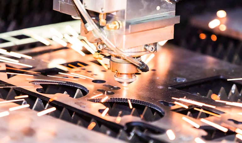
Custom Cut Metal Plate Secrets: From Raw Stock To Finished Part
What Makes Custom Cut Metal Plate Different From Sheet Metal
When you're sourcing materials for a structural project, have you ever wondered why some suppliers quote "plate" while others offer "sheet"? The distinction isn't just semantics—it fundamentally affects your project's performance, cost, and manufacturing approach. Understanding this difference is your first step toward making informed decisions about custom cut metal plate specifications.
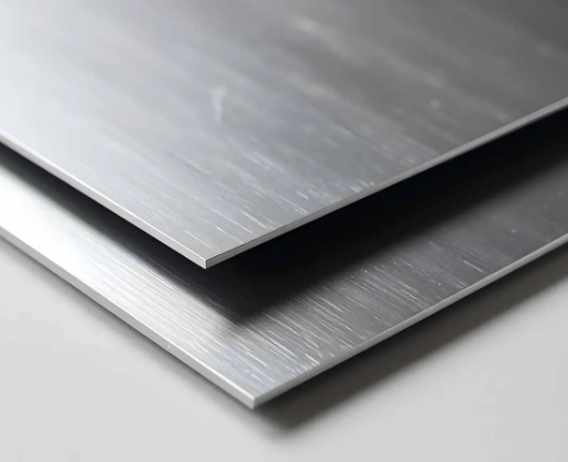
What Defines a Metal Plate vs Sheet Metal
The critical threshold separating a steel plate from sheet metal lies at 3/16 inch (4.76mm) thickness. According to industry standards, any flat-rolled steel product at or above this measurement qualifies as plate, while thinner materials fall into the sheet category. This isn't an arbitrary line—it reflects genuine differences in how these materials perform under stress, how they're manufactured, and what applications they serve best.
Stainless steel sheet metal, for example, typically ranges from very thin gauges up to just under that 3/16-inch mark. These thinner materials excel in applications requiring formability, lighter weight, or decorative finishes. In contrast, metal plate brings the structural integrity needed for load-bearing components, heavy equipment, and demanding industrial environments.
When exploring the various types of metal available for your project, this thickness classification becomes your starting point. Whether you're working with carbon steel, aluminum, or specialty alloys, the plate-versus-sheet distinction applies across the board and influences everything from cutting method selection to final application suitability.
Understanding Thickness Classifications in Metal Fabrication
Metal fabrication projects demand precise thickness specifications. While sheet metal fabrication often uses gauge numbers, plate-thickness materials are typically specified in fractional inches or millimeters. Here are the most commonly ordered plate thicknesses you'll encounter:
- 1/4 inch (6.35mm) — Entry-level plate thickness ideal for moderate structural applications and equipment mounting
- 3/8 inch (9.53mm) — Popular for industrial machine bases and reinforcement brackets
- 1/2 inch (12.7mm) — Standard choice for heavy-duty structural components and wear applications
- 3/4 inch (19.05mm) — Used in demanding load-bearing situations and pressure vessel construction
- 1 inch (25.4mm) — Heavy plate for maximum strength requirements in construction and defense applications
Why does this matter for your project? A metal plate at these thicknesses provides the tensile strength and rigidity that structural applications demand. As noted by Steel Warehouse, steel plate is commonly used in applications requiring strong, durable material—from heavy equipment and bridge construction to pressure vessels and military vehicles.
The distinction also affects your supplier options and manufacturing approach. Discrete plate is produced on reversing mills to achieve specific dimensions, while plate cut from coil offers advantages including smoother finishes, custom lengths that minimize waste, and often better pricing for thicknesses up to 1 inch. Understanding these production methods helps you optimize both quality and cost when ordering custom-cut components for your metal fabrication project.
Choosing the Right Metal Material for Your Custom Plate Project
Now that you understand the thickness classifications that define plate materials, how do you decide which metal actually belongs in your project? This is where many fabrication projects go wrong—selecting materials based on price alone without considering the properties of metals that determine real-world performance. Let's break down the selection criteria that separate successful projects from costly mistakes.
Steel Plate Grades and Their Ideal Applications
Carbon steel remains the workhorse of custom cut metal plate applications, offering an excellent balance of strength, weldability, and cost. However, not all steel grades perform equally in every environment. Understanding grade-specific characteristics helps you match material properties to your project's demands.
For general structural applications, A36 carbon steel provides reliable tensile strength (58,000-80,000 PSI) at the lowest cost point. When your project involves outdoor exposure, galvanized steel and hot-dip zinc coatings protect against corrosion without the premium pricing of stainless alternatives. This makes galvanized plate ideal for agricultural equipment, outdoor signage brackets, and utility applications.
The debate between 304 vs 316 stainless steel often confuses buyers who see both listed without context. Here's the practical difference: 304 stainless steel sheet works perfectly for indoor food processing equipment, architectural trim, and general corrosion resistance needs. However, 316 stainless steel contains molybdenum, which dramatically improves resistance to chlorides and saltwater. If your custom plates will encounter marine environments, chemical processing, or coastal installations, the additional investment in 316 pays dividends through extended service life.
For extreme wear applications, AR500 steel delivers exceptional hardness (470-500 Brinell) that outperforms standard carbon steel by a significant margin. According to Metal Zenith, AR500 is primarily used in environments where durability is paramount, including mining equipment, armor plating, and material handling systems. However, this hardness creates trade-offs—AR500 requires careful welding procedures with preheating and post-weld heat treatment to prevent cracking.
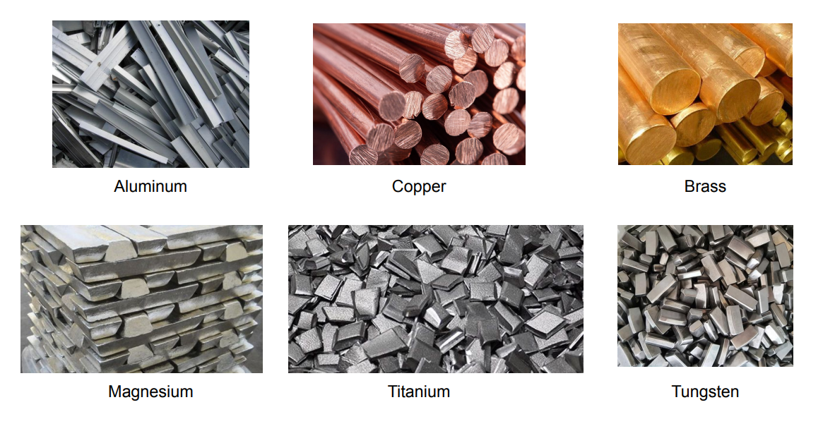
When Aluminum Outperforms Steel for Custom Plates
Imagine you're designing a component where every pound matters—transportation equipment, aerospace assemblies, or portable machinery. This is where aluminum sheet metal demonstrates its value proposition. While steel is approximately 2.5 times denser than aluminum, the lighter metal often provides adequate tensile strength at a fraction of the weight.
According to Industrial Metal Service, aluminum's strength-to-weight ratio allows structural components to weigh significantly less than stainless steel alternatives while still meeting many application requirements. Aircraft and spacecraft can consist of up to 90% aluminum alloys, demonstrating the metal's proven performance in demanding environments.
Aluminum also forms a natural oxide layer that protects against corrosion without additional coatings—a significant advantage over carbon steel in outdoor applications. For projects requiring detailed bending and forming, aluminum's malleability enables intricate geometries that would be difficult or impossible with harder steel grades.
| Material Type | Typical Applications | Corrosion Resistance | Weldability | Relative Cost | Weight Consideration |
|---|---|---|---|---|---|
| Carbon Steel (A36) | Structural frames, mounting plates, general fabrication | Low (requires coating) | Excellent | Lowest | Heavy (0.28 lb/in³) |
| 304 Stainless Steel | Food equipment, architectural, indoor corrosion resistance | Good | Good | Moderate-High | Heavy (0.29 lb/in³) |
| 316 Stainless Steel | Marine hardware, chemical processing, coastal installations | Excellent (chloride resistant) | Good | High | Heavy (0.29 lb/in³) |
| Aluminum Alloys (6061) | Transportation, aerospace, lightweight structures | Excellent (natural oxide layer) | Moderate (requires skill) | Moderate | Light (0.1 lb/in³) |
| AR500 | Wear plates, armor, mining equipment, impact zones | Low (requires coating) | Challenging (special procedures) | Moderate-High | Heavy (0.28 lb/in³) |
When evaluating these options for your custom plate project, consider the complete lifecycle—not just initial material cost. A stainless steel sheet that costs more upfront may eliminate painting, replacement, and maintenance expenses over time. Conversely, carbon steel with proper coating often delivers the best value for indoor structural applications where corrosion isn't a primary concern.
With your material selection criteria established, the next critical decision involves how your custom plates will be cut. Different cutting technologies offer distinct advantages depending on your thickness requirements, tolerance needs, and material type.
Metal Plate Cutting Methods Explained
You've selected your material and specified your thickness—but how will your custom cut metal plate actually be shaped? The cutting method you choose directly impacts edge quality, dimensional accuracy, and even material properties. Yet most suppliers list cutting options without explaining when each technology makes sense. Let's change that by examining the real selection criteria that determine which metal cutter fits your project.
Laser Cutting Precision for Intricate Metal Plate Designs
When your design features tight tolerances, small holes, or intricate patterns, a laser cutter delivers unmatched precision. The focused light beam creates exceptionally clean edges with minimal post-processing, making it ideal for parts that need to fit together precisely or present a finished appearance.
According to testing data from Okdor's fabrication analysis, laser cutting typically achieves ±0.05-0.1mm tolerances for most materials up to 25mm thick. For thinner plates under 10mm, precision tightens even further—reaching ±0.05mm accuracy that satisfies demanding applications in electronics, medical devices, and precision assemblies.
However, laser cutting has practical limitations. The technology excels with thin to medium materials but struggles beyond 25-30mm thickness depending on the metal type. Heat accumulation in thicker sections causes the tolerance to drift toward ±0.1mm or looser, with kerf width variations becoming more pronounced. If your custom plate exceeds this range, alternative methods become necessary.
Interestingly, while laser technology dominates metal cutting discussions, the same precision principles apply to other materials. If you've ever wondered how to cut plexiglass cleanly, laser systems handle acrylic and similar plastics with comparable accuracy—though different power settings and speeds apply.
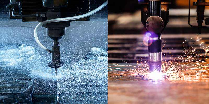
When Plasma or Waterjet Cutting Makes More Sense
Sounds complex? The decision tree is actually straightforward once you understand each technology's sweet spot.
Plasma cutting dominates thick conductive metals where cost efficiency matters more than precision. When you're cutting 1/2-inch steel plate or thicker, plasma offers the best speed-to-cost ratio in the industry. According to Wurth Machinery's technology comparison, plasma cutting through 1-inch steel runs approximately 3-4 times faster than waterjet, with operating costs roughly half as much per foot. The trade-off? Tolerances range from ±0.5-1.5mm—acceptable for structural applications but insufficient for precision assemblies.
Waterjet cutting enters the picture when heat becomes your enemy. The cold-cutting process uses high-pressure water mixed with abrasive to slice through virtually any material without thermal distortion, warping, or heat-affected zones. This makes waterjet essential for:
- Heat-treated materials where you need to preserve hardness properties
- Titanium and exotic alloys prone to work-hardening during thermal cutting
- Thick sections up to 200mm where laser technology cannot reach
- Maximum precision requirements achieving ±0.03-0.08mm tolerances
The waterjet market reflects this demand, projected to reach over $2.39 billion by 2034 as manufacturers recognize its unique capabilities. While slower than plasma and often more expensive than laser cutting, waterjet delivers consistent precision regardless of material thickness—a critical advantage for aerospace and medical components.
CNC routing serves a different niche, primarily handling softer materials and non-metals where traditional cutting methods prove impractical. Similar to how a die cut machine creates shapes through mechanical force, CNC routers use spinning bits to remove material progressively—useful for wood, plastics, and composite panels but rarely the first choice for steel or aluminum plate.
Cutting Method Comparison: Making the Right Choice
The following table summarizes key selection criteria across all four cutting technologies:
| Cutting Method | Maximum Thickness | Edge Quality | Heat-Affected Zone | Material Compatibility | Precision Tolerance |
|---|---|---|---|---|---|
| Laser Cutting | 25-30mm (material dependent) | Excellent—minimal burr | Present (0.2mm typical) | Most metals, some plastics | ±0.05-0.1mm |
| Plasma Cutting | 100mm+ on conductive metals | Good—may need finishing | Significant | Conductive metals only | ±0.5-1.5mm |
| Waterjet Cutting | 200mm (all materials) | Excellent—smooth finish | None (cold cutting) | Any material | ±0.03-0.08mm |
| CNC Routing | Variable by material | Good—tool marks possible | Minimal | Wood, plastics, composites | ±0.1-0.25mm |
Understanding kerf width—the material removed by the cutting process—becomes critical for tight-tolerance parts. Laser cutting produces the narrowest kerf (typically 0.1-0.3mm), allowing parts to nest closely together and minimizing material waste. Plasma kerf runs wider (3-5mm), requiring greater spacing between parts and more stock material. Waterjet kerf falls in between (0.5-1.5mm depending on nozzle size and abrasive flow).
For your custom plate project, start with thickness and tolerance requirements to narrow your options, then factor in material type and budget constraints. Many fabrication shops offer multiple technologies precisely because no single method serves all applications optimally.
With cutting methods clarified, the next challenge involves understanding thickness specifications—particularly the confusing relationship between gauge numbers and actual measurements that affects how you communicate requirements to suppliers.
Understanding Metal Plate Thickness and Gauge Specifications
Ever looked at a material spec sheet and wondered why 10 gauge steel is thicker than 16 gauge? The gauge system confuses even experienced fabricators because it works backward from intuition. Understanding this measurement system—and knowing when to abandon it entirely for plate-thickness materials—saves ordering mistakes and ensures your custom cut metal plate meets actual project requirements.
Reading Steel Gauge Charts for Plate Thickness
The gauge system originated in the British wire industry before standardized measurements existed. Manufacturers measured wire by counting how many times it passed through drawing dies—more passes meant thinner wire and higher gauge numbers. This historical quirk explains why steel gauge thickness works inversely: lower gauge numbers indicate thicker material.
Here's where confusion multiplies: different metals use different gauge charts. According to Stepcraft's reference documentation, 14 gauge steel measures 0.0747 inches (1.897mm), while 14 gauge aluminum is only 0.06408 inches (1.628mm). That's a 0.033-inch difference—well outside acceptable tolerances for most precision applications. Using the wrong gauge chart can derail your entire project.
The following table displays common metal gauge thickness conversions for mild steel, the most frequently ordered material for custom plate fabrication:
| Gauge Number | Thickness (Inches) | Thickness (MM) | Common Applications |
|---|---|---|---|
| 10 Gauge | 0.1345" | 3.416mm | Equipment enclosures, heavy brackets |
| 11 Gauge | 0.1196" | 3.038mm | Industrial shelving, machine guards |
| 12 Gauge | 0.1046" | 2.656mm | Automotive panels, trailer components |
| 14 Gauge | 0.0747" | 1.897mm | HVAC ductwork, light structural work |
| 16 Gauge | 0.0598" | 1.518mm | Decorative panels, light enclosures |
Notice how 11 gauge steel thickness (0.1196") sits just below the 3/16-inch plate threshold discussed earlier. This makes 10 gauge the thickest material commonly specified using the gauge system—anything heavier typically transitions to fractional inch or millimeter specifications.
Converting Between Gauge Numbers and Actual Measurements
When should you use gauge numbers versus direct measurements? The industry convention is straightforward: gauge specifications work for sheet metal applications, while plate-thickness materials (3/16 inch and above) use fractional inches or millimeters. As SendCutSend's material guide notes, metals beyond 1/4 inch thickness are considered plate metal and measured with decimal or fractional thickness rather than gauge numbers.
This distinction matters for communication accuracy. When you specify 12 gauge steel thickness (0.1046") to a supplier, they understand you want sheet-category material. Specifying "1/4 inch A36 plate" signals structural-grade material processed differently at the mill. Mixing terminology creates confusion and potential ordering errors.
For practical conversions, remember these key reference points:
- 16 gauge steel thickness (0.0598") approximates 1/16 inch—useful for lightweight fabrication
- 14 gauge steel thickness (0.0747") falls between 1/16 and 1/8 inch—the workhorse sheet thickness
- 10 gauge (0.1345") approaches 1/8 inch—transitional zone toward plate
- 3/16 inch (0.1875") marks the official plate threshold
Selecting Thickness for Your Application
Beyond understanding the gauge size chart, you need practical guidance for matching thickness to project demands. Three factors drive this decision: load requirements, welding considerations, and cost optimization.
Load requirements dictate minimum thickness. Structural engineers calculate deflection and stress concentrations to determine appropriate plate gauge for load-bearing applications. For non-engineered projects, a general rule applies: double the thickness when loads or spans increase significantly. A mounting bracket supporting 50 pounds might work fine in 14 gauge steel, but scaling to 200 pounds likely demands 3/8-inch plate.
Welding considerations influence thickness selection because thinner materials require more careful heat control to prevent burn-through and distortion. Materials thinner than 16 gauge often need specialized techniques like pulse welding or TIG processes. Conversely, very thick plate (over 1/2 inch) may require preheating and multi-pass welds that increase fabrication time and cost.
Cost optimization involves balancing material weight against processing requirements. Thicker materials cost more per square foot but may reduce fabrication complexity—eliminating reinforcement pieces or secondary stiffening operations. For large production runs, even small thickness optimizations compound into significant savings.
Different cutting technologies also impose thickness limitations. Laser cutting excels up to approximately 25mm (1 inch), while plasma handles thicker sections more economically. Waterjet cuts virtually any thickness but at slower speeds. Your gauge size selection should align with available cutting capabilities to avoid processing delays or quality compromises.
With thickness specifications clearly understood, the next step involves translating your project requirements into a properly documented order—a process where clear communication prevents costly mistakes.
How to Specify and Order Custom Cut Metal Plates
You've determined your material, understood thickness specifications, and selected an appropriate cutting method. Now comes the step where projects often derail—translating those decisions into a properly documented order. Whether you're ordering sheet metal cut to size for a one-off prototype or scheduling production runs for hundreds of custom metal plates, clear specifications prevent costly mistakes and delays.
Preparing Your Custom Metal Plate Specifications
Think of your order specifications as a communication bridge between your design intent and the fabricator's production floor. Missing information forces suppliers to make assumptions—sometimes correctly, often not. Follow this step-by-step process to ensure your custom cut metal requirements translate accurately:
- Determine material type and grade. Specify both the base metal (carbon steel, stainless steel, aluminum) and the exact grade (A36, 304, 6061-T6). As discussed in earlier sections, grade-specific properties affect everything from weldability to corrosion resistance. Simply ordering "stainless steel" without specifying 304 versus 316 leaves critical decisions to someone unfamiliar with your application.
- Specify exact dimensions with tolerances. Include length, width, and thickness using consistent units—mixing inches and millimeters creates conversion errors. For metal cut to size applications, communicate acceptable variation using industry-standard notation: ±0.005" for precision parts or ±0.030" for general fabrication. According to Protolabs' fabrication guidelines, tolerance specifications directly impact processing methods and pricing.
- Choose cutting method based on requirements. If your tolerances or material dictate a specific technology, state it explicitly. Otherwise, indicate "fabricator's choice" to allow cost optimization. Remember that laser cutting delivers ±0.05-0.1mm precision while plasma tolerances run ±0.5-1.5mm—a significant difference for assemblies requiring precise fit.
- Select edge finish and secondary operations. Raw cut edges may have burrs, dross, or slight taper depending on cutting method. Specify if you need deburred edges for safe handling, ground surfaces for welding preparation, or specific edge profiles. Protolabs notes that minimum flange length on formed parts must be at least 4 times the material thickness—a detail easily overlooked during initial ordering.
- Specify quantity and delivery timeline. Production scheduling depends on order size and urgency. Rush orders typically carry premium pricing, while larger quantities may unlock volume discounts. Be realistic about lead times—custom cut stainless steel often requires longer processing than standard carbon steel due to material handling requirements.
File Format Requirements for Custom Shapes
When your project involves complex geometries rather than simple rectangles, digital files become essential. According to SendCutSend's drawing guidelines, fabricators accept specific formats for production-ready parts:
- 2D vector files: DXF, DWG, EPS, or AI (Adobe Illustrator) format—these define flat patterns for laser, plasma, and waterjet cutting
- 3D files: STEP or STP format for parts requiring bending or forming operations
- Avoid: Mesh files, image files (JPEG, PNG, PDF), and assembly files containing multiple parts
Critical file preparation requirements include ensuring all cut paths form closed shapes, removing stray points and duplicate lines, converting text to outlines, and building files at 1:1 scale in inch or millimeter units. Open entities—cut paths that don't form complete loops—will cause processing errors and delay your order.
Common Ordering Mistakes and How to Avoid Them
Even experienced buyers make specification errors that create production delays, rejected parts, or unexpected costs. Here are the most frequent pitfalls:
- Ignoring minimum feature sizes. Holes and cutouts must meet technology-specific minimums. Laser cut parts require holes at least 50% of material thickness. Waterjet cut parts need minimum 0.070" features, while CNC routed parts require 0.125" minimum. Specifying smaller features than your cutting method can produce forces redesign mid-order.
- Overlooking hole-to-edge distance. According to Protolabs' guidelines, holes in material 0.036" or thinner should sit at least 0.062" from edges; thicker materials require 0.125" minimum spacing to prevent distortion during cutting.
- Forgetting tolerance stack-up. When multiple custom metal cutting operations combine—cutting plus bending plus hardware insertion—tolerances accumulate. A part holding ±0.010" on each of three operations could vary ±0.030" total. Design your assemblies with appropriate clearances.
- Submitting nested files without proper spacing. If you're nesting multiple parts in a single file to optimize material usage, ensure parts don't share cut paths or overlap. Each part needs independent closed contours with appropriate spacing for the cutting technology's kerf width.
The Value of Design for Manufacturing Review
Before committing to production quantities, request a DFM (Design for Manufacturing) review from your fabrication partner. This engineering evaluation identifies potential issues before they become expensive problems:
- Features too small or too close for reliable cutting
- Material choices that complicate processing without adding value
- Design modifications that reduce cost without compromising function
- Tolerance specifications tighter than your application actually requires
A thorough DFM review transforms your design intent into production-optimized specifications. Minor adjustments—moving a hole slightly, opening a tolerance marginally, or adjusting a bend radius to match standard tooling—can reduce costs significantly while maintaining functional performance.
With your specifications properly documented and files prepared, you're ready to place an order with confidence. The next consideration involves understanding how different industries apply these custom cut plates—and how application-specific requirements might influence your own project decisions.
Common Applications for Custom Cut Metal Plates
What will your custom cut metal plate actually become? Understanding how different industries apply these materials helps you make smarter decisions about specifications, material selection, and processing requirements. From load-bearing structural components to decorative architectural elements, each application category brings unique demands that influence every upstream choice you've already made.
Structural and Industrial Metal Plate Applications
Structural steel fabrication represents the largest demand category for custom plates, where material integrity directly affects safety and performance. According to Continental Steel, metal plates serve applications including structural components for buildings and bridges, vehicle underframes, and heavy equipment foundations. Steel fabricators rely on precise specifications because these components bear loads, resist impacts, and maintain dimensional stability over decades of service.
Here are the primary structural and industrial applications organized by category:
-
Structural Fabrication:
- Base plates for column connections (typically 1/2" to 1" A36 steel)
- Mounting brackets for machinery and equipment (3/8" to 3/4" depending on load)
- Reinforcement gussets for beam connections
- Bridge bearing plates and splice plates
-
Industrial Equipment:
- Machine guards protecting operators from moving parts (10-14 gauge steel or aluminum)
- Wear plates lining chutes and hoppers (AR500 for abrasion resistance)
- Equipment housings and electrical enclosures (12-16 gauge stainless for corrosion resistance)
- Conveyor components and material handling systems
-
Automotive Components:
- Chassis reinforcement plates (3/16" to 1/4" high-strength steel)
- Suspension mounting brackets requiring precise tolerances
- Skid plates and underbody protection (aluminum for weight savings)
- Custom brackets for aftermarket modifications
Material recommendations vary significantly across these categories. Structural applications typically demand carbon steel for its weldability and cost-effectiveness—A36 remains the standard choice for general construction. Industrial wear applications often justify AR500's higher cost through extended service life. Automotive components increasingly specify aluminum to reduce vehicle weight, though aluminum welding requires specialized techniques and equipment that not all metal fab shops offer.
Weldability becomes critical for fabricated assemblies where multiple steel plates join together. Carbon steel welds readily using standard MIG and stick processes, making it ideal for field assembly. Stainless steel requires cleaner preparation and often TIG welding for optimal results. As noted by Fictiv's fabrication guide, techniques like MIG, TIG, and spot welding assemble multiple components into single parts, offering precision and strong bonds essential for structural integrity.
Custom Plates for Prototyping and Small-Batch Production
Imagine you're developing a new product and need to validate your design before committing thousands of dollars to production tooling. This is where rapid prototyping capabilities transform the development process. Modern sheet metal prototyping enables engineers to test and refine designs quickly, with prototype parts produced within days rather than weeks.
According to Fictiv's analysis, prototype fabrication uses standard production techniques—bending, cutting, punching, and welding—resulting in functional parts that replicate key attributes of the final design. This approach supports real-world testing for performance, durability, and assembly fit before committing to mass production.
Key advantages of prototyping with actual production materials include:
- Functional validation: Testing with production-grade materials reveals actual mechanical behavior, thermal characteristics, and assembly fit
- Design iteration speed: Digital workflows enable rapid design changes—modify a CAD file, receive updated parts in days
- Cost-effective low-volume production: No expensive tooling required, making small batches economically viable
- Risk reduction: Identify design flaws before committing to full-scale manufacturing
The prototyping approach works particularly well for custom metal signs and decorative applications where visual appearance matters as much as structural function. Fabricators can produce single pieces for client approval before cutting production quantities—eliminating the expensive "discover problems during installation" scenario.
Decorative and Architectural Applications
Beyond purely functional uses, custom plates create striking visual elements in architectural and commercial settings. Custom metal signs represent a growing market segment where laser-cut precision enables intricate logos, lettering, and artistic designs impossible with traditional fabrication methods.
-
Decorative Projects:
- Custom metal signs for businesses and wayfinding
- Architectural wall panels and facade elements
- Artistic installations and sculptures
- Furniture components and decorative hardware
-
Recommended Materials:
- Aluminum for lightweight outdoor installations (natural corrosion resistance)
- Stainless steel for modern aesthetic and durability
- Weathering steel (Corten) for rustic architectural features
- Brass and copper for traditional or accent applications
Thickness selection for decorative applications balances visual impact with practical handling. Thinner materials (14-16 gauge) work well for wall-mounted signs and panels, while freestanding elements often require 3/16" to 1/4" plate for rigidity. Steel fabricators experienced in architectural work understand how thickness affects perceived quality—too thin looks flimsy, while excessive thickness adds unnecessary weight and cost.
Surface finishing becomes especially important for decorative applications. Powder coating provides durable color options, brushed finishes create contemporary aesthetics, and clear coatings preserve natural metal patina. These finishing considerations—explored in detail in the following section—often determine whether a custom plate project achieves its intended visual impact.
Understanding Custom Metal Plate Pricing Factors
Ever received a custom cut metal plate quote and wondered how the fabricator arrived at that number? Pricing transparency remains one of the biggest gaps in the metal fabrication industry. While competitors list services and capabilities, few explain what actually drives costs—leaving buyers guessing whether they're getting fair value. Let's demystify the pricing equation so you can make informed decisions and optimize your budget.
What Drives Custom Metal Plate Pricing
According to Metaltech's fabrication cost analysis, shop estimators calculate pricing based on material, design complexity, labor, and finishing processes. Understanding these factors helps you anticipate costs before requesting quotes—and identify opportunities to optimize without sacrificing quality.
Here are the primary cost factors that determine your final price:
- Material type and grade: Raw material costs vary significantly between metals. Carbon steel costs less than stainless steel, while aluminum falls somewhere in between. Within each category, specialty grades command premium pricing—316 stainless costs more than 304, and AR500 exceeds standard structural steel. Market fluctuations also affect pricing; as Metaltech notes, hot-rolled steel prices swung from $1,080 to $1,955 per ton during recent supply chain disruptions.
- Plate thickness: Thicker metal sheets cost more per square foot and require longer processing times. Standard gauge sizes cost less than custom thicknesses because mills produce them in higher volumes with established processes.
- Total square footage: Larger projects benefit from material efficiency gains, but also require more cutting time and handling. The relationship isn't strictly linear—setup costs get distributed across more parts in larger orders.
- Cutting complexity: Simple rectangles cost less than intricate patterns. Every cut, curve, and interior feature adds machine time and programming complexity. Tight tolerances require slower cutting speeds and more careful quality control.
- Quantity: Larger orders reduce per-piece costs because machine setup happens only once. Programming a laser cutter or plasma table takes the same time whether you're cutting one piece or one hundred—that fixed cost gets distributed across all parts.
- Secondary operations: Bending, welding, and finishing add value but increase cost. A flat cut plate costs less than one requiring CNC bending into a bracket. Spot welding multiple components into an assembly adds labor time. Each additional operation requires handling, setup, and quality verification.
- Turnaround time: Rush orders carry premium pricing because they disrupt production schedules and may require overtime labor. Standard lead times typically offer the best value.
Design complexity deserves special attention because it compounds across multiple factors. According to Metaltech's analysis, every cut, bend, weld, and punch adds time and labor. Intricate geometries with tight tolerances take longer to design, program, and produce—plus they may require specialized tooling that adds setup costs.
How Nesting Optimization Reduces Material Waste
When you're ordering multiple parts, how they're arranged on the raw material dramatically affects your cost. Nesting optimization—strategically positioning parts to minimize waste—can deliver substantial savings that go directly to your bottom line.
According to Consac's nesting analysis, material costs typically represent 50-75% of total sheet metal production expenses. Even a 5% improvement in material efficiency can save thousands of dollars annually. Fabrication shops using automated nesting solutions report 15-30% material savings compared to manual layout methods.
Effective nesting strategies include:
- Mixed-part nesting: Combining different part types on the same sheet fills odd-shaped spaces with smaller components, dramatically reducing waste
- Common-line cutting: Positioning parts to share cutting lines reduces both material waste and cutting time—one cut instead of two where parts share edges
- Part rotation: Allowing parts to rotate at various angles (not just 90-degree increments) finds more efficient arrangements
- Remnant management: Tracking and reusing leftover pieces for smaller jobs rather than scrapping them
The measurable benefits are significant: optimized nesting typically delivers 15-25% material savings, 30% less scrap requiring disposal, and 20% faster production through efficient cutting paths. Most shops recover nesting software costs within 3-6 months through material savings alone.
Strategies to Optimize Your Metal Cutting Budget
How do you balance quality requirements with budget constraints? Start by understanding where flexibility exists in your specifications—and where it doesn't.
Order quantity trade-offs: Single-piece orders offer maximum flexibility but carry higher per-unit costs because setup time can't be distributed. Larger production runs reduce per-piece pricing significantly—but require upfront commitment and storage for finished parts. For prototyping, single pieces make sense despite higher unit costs. For production components, batching orders strategically optimizes the cost curve.
Material selection optimization: Choose materials appropriate for your application rather than over-specifying. Carbon steel with proper coating often delivers equivalent performance to stainless steel at lower material cost—though coating adds a secondary operation. Standard thicknesses and sizes cost less than custom dimensions because they require no special mill processing.
Design for manufacturability: Simplify designs where possible without compromising function. As Metaltech advises, only include features like blind holes and beveled edges if necessary. Simple angles and consistent bends make fabrication more effective, reducing lead times and costs. Reserve tight tolerances for surfaces critical to part function—looser tolerances elsewhere reduce processing time.
Surface Finishing Costs: Powder Coat and Anodizing Considerations
Secondary finishing operations protect your custom plates and enhance appearance—but they add measurable cost to every project. Understanding these options helps you specify appropriately.
Powder coating uses electrically charged pigmented resins to create durable, attractive finishes. According to Metaltech, powder-coated finishes resist run-off and drips while lasting many years under proper conditions. You can customize color, gloss, and texture—but each finishing option adds cost to your project estimate. Powder coat makes sense for parts requiring corrosion protection, consistent color, or professional appearance.
Anodizing applies primarily to aluminum, creating an oxide layer that becomes integral to the substrate rather than sitting on top. Unlike coatings that can chip or peel, anodic oxide finishes become one with the aluminum, providing excellent corrosion resistance and durability. The process costs more than powder coating but offers superior performance for aluminum components in demanding environments.
For assemblies requiring welding aluminum components, consider finishing requirements carefully. Anodizing and powder coating typically happen after welding—but welding previously finished surfaces requires stripping and refinishing. Planning your process sequence avoids expensive rework.
When budgets are tight, prioritize finishing on exposed surfaces while leaving hidden areas uncoated. Interior brackets hidden inside assemblies rarely justify the same finish quality as visible exterior panels. This selective approach maintains appearance where it matters while optimizing overall project cost.
With pricing factors understood, you're better equipped to evaluate quotes and optimize specifications. The next consideration involves understanding secondary operations—bending, forming, and finishing processes that transform flat cut plates into finished components ready for installation or assembly.
Secondary Operations and Finishing for Metal Plates
Your custom cut metal plate arrives precisely shaped—but is it ready for installation? For most applications, the answer is no. Raw cut plates require secondary operations that transform flat stock into functional components with proper edges, formed shapes, and protective finishes. Understanding these post-cutting processes helps you specify complete parts rather than intermediates that need additional work.
Bending and Forming Custom Metal Plates
Imagine transforming a flat steel plate into a three-dimensional bracket, enclosure, or structural component—all without welding separate pieces together. CNC press brake forming makes this possible by applying controlled force along precise lines to create predetermined angles and complex geometries.
According to North Shore Steel's fabrication analysis, press brake forming has evolved from manually operated processes to computer-controlled systems that deliver exceptional accuracy. CNC press brakes support precise, repeatable bends as well as multi-step bends and complex geometries through computer-controlled programming. This flexibility reduces setup times, increases production speed, and enables different bend sequences without tooling changes.
Three primary bending techniques serve different precision requirements:
- Air bending: The most common method using three contact points, allowing flexibility in angle variation—ideal for general fabrication where tolerances of ±0.5-1 degree are acceptable
- Bottoming: Higher force presses steel into the die for more accurate angles—suitable when tighter tolerances matter
- Coining: Maximum pressure stamps permanent bends with the tightest tolerances—reserved for critical applications where precision justifies additional cost
Material thickness directly affects bending capabilities. Depending on the machine's tonnage and configuration, press brakes accommodate everything from light-gauge sheet to heavy plate steel over an inch thick. However, thicker materials require larger minimum bend radii to prevent cracking—a constraint that influences design decisions early in the project.
For automotive structural components like chassis reinforcements and suspension mounts, the combination of precision cutting with expert forming becomes critical. IATF 16949-certified manufacturers like Shaoyi Metal Technology combine precision cutting with stamping and assembly capabilities, offering comprehensive DFM support to optimize complex fabricated parts from initial design through production.
Surface Finishing Options for Durability and Aesthetics
What happens when bare steel or aluminum meets the real world? Without protective finishing, oxidation begins immediately—visually degrading your components and eventually compromising structural integrity. Selecting appropriate surface treatments extends service life while achieving desired aesthetics.
Here are the primary finishing options available for custom metal plates:
- Powder coating for durability: According to Protolabs' finishing guide, powder coating works by spraying polymer-based colored powder through a special gun that charges particles as they pass, making them stick to the surface. The coated part then cures in a hot oven. Powder coating is thicker than traditional wet paint, more durable, and fade-resistant—ideal for industrial equipment, outdoor installations, and any application requiring consistent color and corrosion protection.
- Anodizing for aluminum: Unlike coatings that sit on top of material, anodized aluminum incorporates the protective oxide layer into the substrate itself. Parts are usually sealed immediately after anodizing in a bath of nickel acetate or hot deionized water, closing off microscopic pores and generating different performance characteristics including improved bonding and lubricity.
- Galvanizing for outdoor steel: Hot-dip zinc coatings protect carbon steel in harsh outdoor environments at lower cost than stainless steel alternatives. Galvanized sheet metal works well for agricultural equipment, utility structures, and any steel application facing weather exposure.
- Brushed or polished finishes: Decorative applications often demand aesthetic surface treatments. Brushed finishes create contemporary appearances suitable for architectural elements, while polished surfaces deliver mirror-like reflections for high-end installations.
For stainless steel sheets, passivation provides additional protection by converting the outer surface to an exceedingly thin oxide layer. This process removes stray iron from machining operations and further reduces corrosion potential—particularly important for food processing equipment and medical applications.
When working with tig welded aluminum components, finishing sequence matters significantly. Welding after anodizing destroys the protective layer and requires complete refinishing. Plan your process so welding completes before any surface treatment begins.
Assembly Services and Welding Operations
Many projects require more than individual cut and formed plates—they need complete fabricated assemblies. Spot welding and other joining methods combine multiple components into single functional units ready for installation.
Spot welding creates localized fusion points that join overlapping sheets without continuous weld beads. This technique works particularly well for:
- Enclosure assemblies where structural strength matters more than watertight seams
- Automotive brackets and mounting components
- High-volume production where weld speed affects overall cost
- Applications where visible weld lines would detract from appearance
For structural assemblies requiring full-penetration welds, MIG and TIG processes create continuous bonds that develop complete strength across joined surfaces. Material selection influences welding approach—carbon steel welds readily using standard processes, while stainless steel and aluminum require specialized techniques and filler materials.
Deburring and Edge Finishing for Safe Handling
Every cutting process leaves some edge condition that may require attention. Laser cutting typically produces minimal burr, while plasma cutting often leaves dross requiring removal. Even clean-cut edges can be sharp enough to cause handling injuries without proper finishing.
Edge treatment options include:
- Deburring: Removing raised edges and sharp projections for safe handling
- Edge rounding: Creating consistent radii that eliminate sharp corners
- Chamfering: Beveling edges at specific angles for welding preparation or aesthetic purposes
- Grinding: Smoothing cut surfaces for tight-tolerance assembly fit
For parts entering assembly operations, proper edge preparation directly affects weld quality. Clean, properly prepared edges ensure consistent penetration and reduce defect rates in finished assemblies.
Tolerance Considerations When Combining Operations
Here's a critical consideration many buyers overlook: tolerances accumulate across multiple operations. A plate cut to ±0.1mm that's then bent to ±0.5 degrees and punched with holes at ±0.1mm may show total variation exceeding any single specification.
According to North Shore Steel's analysis, CNC-controlled press brakes typically offer the best accuracy and repeatability, but achieving tight final tolerances requires coordination across all operations. When specifying complex parts, consider:
- Process sequence: Some operations should happen before others to maintain critical dimensions
- Reference surfaces: Identify which features must maintain tight relationships and communicate these priorities
- Inspection points: Define where measurements verify compliance—after cutting, after bending, or only on finished parts
- Acceptable variation: Recognize that tighter tolerances cost more and specify only where function demands precision
Working with fabricators who offer comprehensive DFM support helps identify potential tolerance issues before production begins. Shaoyi Metal Technology's 5-day rapid prototyping capability enables design validation for complex automotive and industrial components—catching tolerance stack-up problems before committing to mass production.
With secondary operations and finishing options understood, you're equipped to specify complete components rather than intermediate parts requiring additional work. The final step involves synthesizing all these considerations into a coherent decision framework that matches your specific project requirements to the right solutions.
Making Informed Decisions for Your Custom Metal Plate Project
You've now explored every critical aspect of custom cut metal plate fabrication—from understanding thickness classifications to selecting materials, choosing cutting methods, and specifying secondary operations. But how do you synthesize all this knowledge into actionable decisions for your specific project? The answer lies in a structured decision framework that matches your requirements to the right solutions.
Matching Your Project Requirements to the Right Solution
Every successful custom steel plate project starts with one fundamental question: what does your application actually demand? Before searching for metal fabrication near me or requesting quotes from fabrication shops near me, establish clear answers to these core requirements.
Understanding your application requirements drives every subsequent decision—from material selection to cutting method to finishing specifications. Start with function, not features.
Here's how to match your project type to the optimal solution path:
- Structural applications demand appropriate thickness (typically 1/4" to 1" plate) and weldable grades like A36 carbon steel. Prioritize material integrity and reliable weld characteristics over tight tolerances. Plasma cutting often provides the best cost-to-quality balance for thicker structural components.
- Precision parts require laser cutting with ±0.05-0.1mm tolerances. Specify exact dimensions with proper tolerance notation and provide production-ready CAD files. These applications justify higher per-piece costs because accuracy prevents assembly problems downstream.
- Cost-sensitive projects benefit from material optimization and efficient nesting strategies. Consider standard thicknesses over custom dimensions, simplify geometries where function permits, and batch orders to distribute setup costs across more parts.
- Corrosion-critical applications demand appropriate material selection from the start. Stainless steel, galvanized carbon steel, or aluminum with anodizing—choose based on environment severity rather than defaulting to the cheapest option.
- Weight-sensitive applications often justify aluminum's premium pricing through downstream benefits. Transportation, portable equipment, and aerospace applications gain measurable value from every pound eliminated.
According to fabrication experts at TMCO, choosing the right metal fabrication partner is a critical decision that affects cost, performance, quality, and long-term reliability. The true value lies in craftsmanship, technology, scalability, and a proven commitment to quality—not just the lowest quoted price.
Getting Started With Your Custom Metal Plate Order
Ready to move from planning to production? Follow this streamlined approach to ensure your custom cut metals order proceeds smoothly from quote to delivery.
Step 1: Document your specifications completely. Before contacting any supplier, prepare a specification package including material type and grade, exact dimensions with tolerances, required thickness, cutting method preference (or "fabricator's choice"), edge finish requirements, quantity needed, and delivery timeline. Missing information delays quotes and introduces assumption errors.
Step 2: Prepare production-ready files. For custom shapes, provide 2D vector files (DXF, DWG, or AI format) with all cut paths forming closed shapes. Remove stray points, convert text to outlines, and build files at 1:1 scale. For parts requiring bending, include 3D STEP files showing final formed geometry.
Step 3: Request DFM review before production. As noted by IMS Manufacturing, partnering closely with your fabricator makes a significant difference. Sharing CAD files, discussing potential challenges, and being open to feedback improves design and streamlines manufacturing. Minor design modifications can reduce costs substantially while maintaining functional performance.
Step 4: Validate with prototypes when stakes are high. For new designs, complex assemblies, or high-volume production runs, prototype validation catches problems before they become expensive. Rapid prototyping capabilities enable testing with production-grade materials—revealing actual mechanical behavior and assembly fit before committing to full quantities.
Step 5: Evaluate partners on more than price. Experience, in-house capabilities, engineering support, quality certifications, and communication transparency matter as much as quoted pricing. According to TMCO's analysis, a trusted fabrication partner doesn't just build parts—they support your goals, improve your product, and help position your project for long-term success.
Partnering for Success
The complexity of custom metal plate projects—spanning material science, cutting technology, forming operations, and finishing processes—rewards partnerships with full-service fabricators who understand your end application.
For automotive and industrial applications requiring precision metal components, manufacturers like Shaoyi Metal Technology demonstrate what comprehensive support looks like in practice. Their 5-day rapid prototyping capability enables design validation before production commitment, while their 12-hour quote turnaround accelerates project planning. IATF 16949 certification confirms quality systems appropriate for chassis, suspension, and structural components where reliability is non-negotiable.
Whether you're fabricating structural steel for construction, precision brackets for industrial equipment, or custom cut steel plate for specialized applications, the decision framework remains consistent: define requirements clearly, specify materials and processes appropriately, validate designs before volume production, and partner with fabricators whose capabilities match your project demands.
Your custom cut metal plate project deserves more than guesswork. Armed with the knowledge from this guide, you're equipped to make informed decisions that optimize cost, quality, and performance—transforming raw stock into finished parts that perform exactly as intended.
Frequently Asked Questions About Custom Cut Metal Plates
1. How much does custom sheet metal fabrication cost?
Custom sheet metal fabrication costs vary based on material type, thickness, cutting complexity, quantity, and secondary operations like bending or powder coating. Material costs typically represent 50-75% of total production expenses. Carbon steel costs less than stainless steel or aluminum. Simple rectangles cost less than intricate patterns, and larger orders reduce per-piece costs since setup happens only once. Rush orders carry premium pricing. For accurate pricing, provide complete specifications including material grade, exact dimensions with tolerances, and finishing requirements when requesting quotes.
2. How to cut a metal plate at home?
For thin sheet metal (under 16 gauge), tin snips work for straight cuts. Thicker metal plates require power tools like angle grinders with cut-off wheels, reciprocating saws with metal blades, or plasma cutters for heavy sections. However, professional laser, plasma, or waterjet cutting delivers superior edge quality and precision that home methods cannot match. Professional cutting achieves tolerances of ±0.05-0.1mm versus rough cuts from hand tools, making it worthwhile for parts requiring accurate dimensions or clean edges for welding.
3. How much does metal laser cutting cost?
Laser cutting steel generally costs $13-$20 per hour of machine time. Actual project costs depend on cutting length, material thickness, and complexity. For example, 15,000 inches of cutting at 70 inches per minute translates to approximately 3.57 hours of active cutting. Additional factors include material cost, nesting efficiency, edge finishing requirements, and quantity. Laser cutting offers the best precision (±0.05-0.1mm) for thin to medium materials up to 25-30mm, while plasma cutting handles thicker sections more economically at looser tolerances.
4. What is the difference between metal plate and sheet metal?
The critical threshold separating plate from sheet metal is 3/16 inch (4.76mm) thickness. Materials at or above this measurement qualify as plate, while thinner materials fall into the sheet category. This distinction reflects genuine differences in performance, manufacturing, and applications. Sheet metal excels in applications requiring formability and lighter weight, while plate provides structural integrity for load-bearing components and heavy equipment. Plate materials use fractional inch or millimeter specifications rather than gauge numbers common for sheet metal.
5. What file formats do fabricators accept for custom metal cutting?
Professional fabricators accept specific production-ready formats. For 2D flat patterns, provide DXF, DWG, EPS, or AI (Adobe Illustrator) files with closed cut paths. For 3D parts requiring bending, submit STEP or STP files showing final formed geometry. Avoid mesh files, image files (JPEG, PNG, PDF), and assembly files. Ensure all cut paths form closed shapes, remove duplicate lines and stray points, convert text to outlines, and build files at 1:1 scale in consistent units (inches or millimeters).