 Small batches, high standards. Our rapid prototyping service makes validation faster and easier —
  EN
EN


Copper Plating Services: Why Your RFQ Keeps Missing Critical Specs

What Copper Plating Services Deliver
Some buyers treat copper as a simple finish callout. In real production, it can serve very different purposes, and that difference shapes the entire RFQ.
Copper plating services are controlled processes that apply a copper layer onto a prepared substrate through electrochemical or chemical copper deposition. That copper layer may remain as the final working surface for conductivity, solderability, or dimensional build-up, or it may act as an underplate beneath finishes such as nickel, tin, silver, or gold.
What Copper Plating Services Actually Include
At its core, copper plating means depositing copper onto another material, usually metal and sometimes plastic, after the surface has been properly cleaned and activated. When copper is the final finish, the exposed layer does the job directly. When it is buried under another coating, its role is different. It may improve leveling, support adhesion, or provide a conductive base for the next plated layer.
Why Engineers Choose Copper Plating
- High electrical conductivity for connectors, shielding, and other current-carrying parts.
- Useful solderability in many electronic and microelectronic applications.
- Good leveling characteristics that can help smooth minor surface imperfections.
- Strong value as an intermediate layer in multilayer plating systems.
Common industry references such as Dorsetware and Powder Metallurgy describe these uses in electronics, EMI and RFI shielding, and base layers for nickel, silver, gold, and tin.
Where Copper Works Best and Where It Does Not
- Exposed copper can oxidize or tarnish, so it is not always the best outer finish for harsh environments or appearance-critical parts.
- Wear resistance and long-term cosmetic stability may be better served by another topcoat.
- Some substrates need special preparation or an intermediate layer to achieve reliable adhesion.
Common industrial uses include:
- Printed circuit boards and electrical components
- EMI and RFI shielding applications
- Underplates for nickel, chrome, silver, gold, or tin
- Dimensional build-up or surface smoothing before a final finish
The copper itself is only part of the story. Surface condition, masking, bath choice, and inspection criteria often decide whether the finished part matches the drawing.

How the Copper Plating Process Works
A drawing may call out copper, but the finished result depends on much more than tank time. In practice, the copper plating process starts long before metal deposits on the part, and small decisions at the front end often determine adhesion, coverage, and rework risk.
Surface Preparation Before Copper Plating
Most job shops begin with a quote and part review. That review checks the substrate, geometry, masking zones, thickness targets, and whether the copper will be the final finish or an underplate. From there, preparation becomes critical. Both Powder Metallurgy and Clarwe note that poor cleaning or incomplete activation can lead to blistering, peeling, roughness, or uneven deposition.
- RFQ and part evaluation - Review material, drawing revision, plating intent, masking, and inspection needs.
- Cleaning - Remove oils, dust, and shop soils with chemical cleaning.
- Activation - Use an acid dip or micro-etch to remove oxides and expose a reactive surface.
- Strike layer if needed - Apply a thin starting layer on difficult substrates or before a heavier build.
- Plate copper - Deposit copper by electrolysis, or by electroless chemistry when the application requires it.
- Rinse and dry - Prevent bath carryover, staining, and contamination between steps.
- Post-treatment - Add polishing or anti-tarnish treatment if the specification calls for it.
- Inspection, packaging, and delivery - Verify the release criteria, protect the surface, and ship by lot.
What Happens During the Copper Plating Process
When electroplating copper, the workpiece acts as the cathode and the copper anode helps replenish copper ions in the bath. A DC power supply drives deposition, while bath chemistry, agitation, temperature, current density, and time influence thickness and surface quality. Clarwe highlights current density, pH, temperature, and agitation as core process variables, and Powder Metallurgy also points to bath composition and current control as major factors in deposit quality.
Racking and masking matter just as much. Rack contacts affect current flow. Barrel loading changes part movement and edge contact. Masking determines where metal must not deposit. Even the best bath cannot compensate for poor fixturing or unclear inspection criteria.
Inspection Packaging and Delivery Expectations
| Stage | Purpose | Typical risks | Buyer confirmation |
|---|---|---|---|
| Quote review | Match process to part and drawing | Wrong assumptions on substrate or finish role | Material, revision, final finish vs underplate |
| Cleaning and activation | Prepare an adherent surface | Residual oils, oxides, immersion deposits | Required prep steps for the base metal |
| Strike and plating | Build the specified copper layer | Poor adhesion, pits, edge buildup, thin recesses | Bath family, masking, rack or barrel method |
| Rinse and post-treatment | Prevent carryover and protect fresh copper | Staining, tarnish, contamination | Any anti-tarnish or appearance requirement |
| Inspection and packing | Verify release and protect parts in transit | Damage, mix-ups, unverified thickness | Inspection method, sampling, packaging needs |
That workflow is the baseline. The harder question is which copper method fits the part best, because acid baths, alkaline systems, electroless deposition, and strike layers do not solve the same problems.
Choosing the Right Copper Plating Method
Not all copper processes solve the same problem. In real sourcing work, the best choice depends on what the copper layer must do first: stick, build thickness, reach deep features, restore a worn spot, or create conductivity on a surface that could not be plated conventionally.
A simple screening logic helps buyers and engineers narrow the field:
- If the part needs a thick, highly conductive build, acid copper is often the workhorse.
- If the substrate is active metal and adhesion is the first concern, an alkaline copper start or copper strike may be required.
- If the surface is nonconductive, or the geometry has deep holes and complex recesses, electroless copper plating may be the better fit.
- If only one damaged or functional area needs copper, a selective brush method can be more practical than full immersion.
Acid and Alkaline Copper Plating Compared
Technical guidance on acid copper and alkaline copper describes them as complementary, not interchangeable. In copper electroplating, acid copper is commonly used for fast build-up plating. It produces a bright, ductile, conductive deposit and is well suited when the part already has a compatible surface. Buyers sometimes describe this family as copper plating with copper sulfate, since copper sulfate is the primary copper source in acid copper baths.
Alkaline copper serves a different role. It is commonly used as a thin, adherent first layer on active metals such as steel, zinc die cast, stainless steel, or aluminum, where acid copper can create a weak immersion deposit instead of a reliable plated layer. It is slower and more complex, but much better when adhesion comes before thickness.
When Electroless Copper Plating Makes Sense
Electroless plating becomes attractive when current distribution is the problem. Because it does not rely on external current in the same way as tank electroplating, it can provide more uniform coverage on complex shapes, internal cavities, threads, and deep holes. It is also a practical route for metallizing nonconductive surfaces after proper activation. For some parts, electroless copper plating acts as the first conductive layer before later electroplating builds thickness.
The trade-off is straightforward: it is generally slower, more chemistry-intensive, and not usually the first choice when a thick, low-cost production build is the goal.
How to Choose a Copper Strike or Selective Process
A copper strike is best viewed as a starter layer, not the main event. Use it when the part needs a thin, reliable base that prepares the surface for heavier copper, nickel, or another downstream finish. By contrast, brush copper plating is a localized method. It is useful for touch-up, repair, anti-galling areas, or selective dimensional restoration where full-tank plating would add cost, handling, or unnecessary coverage.
| Process option | Preferred use case | Key strengths | Main limitations |
|---|---|---|---|
| Acid copper electroplating | Heavy build, conductive layers, leveling over a suitable base | Fast deposition, bright and ductile deposit, good conductivity | Not suitable as a direct first layer on active metals |
| Alkaline copper electroplating | First adherent layer on steel, zinc, stainless steel, or aluminum | Better adhesion on active substrates, good micro-coverage | Slower, more complex bath control, often thinner use |
| Electroless copper plating | Nonconductive parts, deep recesses, uniform coverage needs | No edge effect in the same way as electroplating, useful for complex geometry | Higher cost and slower build, less attractive for heavy thickness |
| Copper strike layer | Thin starting layer before further plating | Improves adhesion and creates a reliable base | Usually not intended as the final full-build copper layer |
| Selective brush or touch-up copper | Repair zones, tight local tolerances, on-site or partial-area plating | Localized control, portable setup, avoids plating the whole part | Not ideal for high-volume full-surface production |
Method selection and finish intent are tightly linked. A process that works well for an underplate may be the wrong choice for exposed service, which is exactly why buyers need to separate copper as a foundation layer from copper as the final finish.
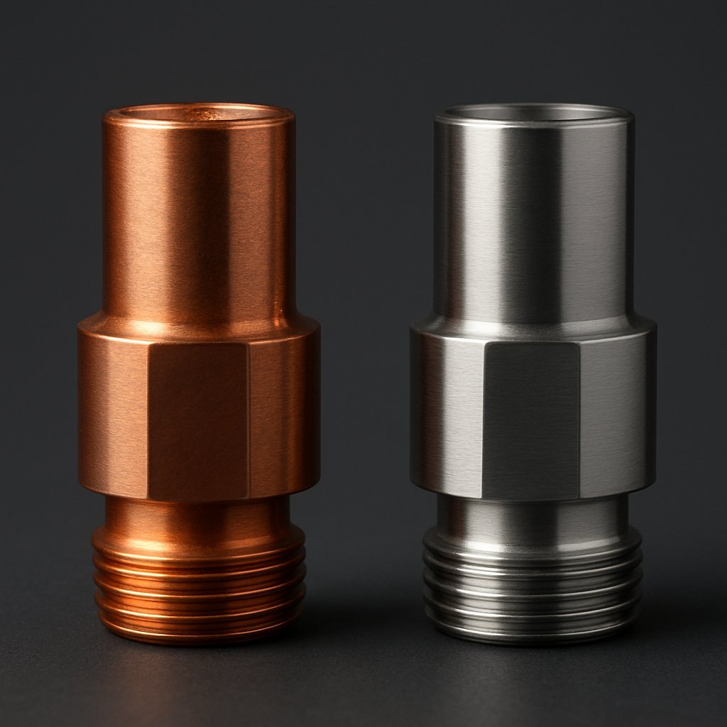
Copper as an Underplate or Final Finish
A copper coated part can mean two very different things on a drawing. Sometimes copper is the working surface the customer will actually use. Just as often, it is a buried layer that helps the next finish do its job.
Copper as an Underplate Layer
In multilayer plating, copper is commonly placed beneath nickel, tin, silver, or gold. Guidance from American Electro describes copper underplates as highly conductive, good at leveling, and useful for uniform deposition and build-up on slightly undersized parts. Techmetals likewise notes that copper can serve either as a final finish or as an underplate in functional and heavy-build applications.
That hidden role matters because the exposed layer may need properties copper does not provide well by itself. Nickel is often chosen for corrosion protection. Tin is a common outer finish where solderability and cost matter. Silver is attractive for high-current contacts. Gold is preferred when long-term contact stability and corrosion resistance are more important. In those stacks, plating copper is less about appearance and more about creating a conductive, level base that supports the rest of the finish system.
When Copper Is Used as the Final Finish
Exposed copper still has valid uses. It can make sense when conductivity, ductility, dimensional build-up, or cost are the main priorities. Techmetals presents copper as an economical finish with excellent conductivity, and not just a hidden intermediate layer. The catch is surface stability. Cooper Plating notes that copper is relatively corrosion resistant, but it can tarnish and stain rapidly in air, which is why it is rarely used alone for long-term exposed service.
That is the practical dividing line. If the part must stay bright, resist a harsh environment, or hold cosmetic appearance over time, another outer finish may be the safer choice. If the job is mainly electrical, dimensional, or temporary in exposure, copper may remain exposed, sometimes with an anti-tarnish post-treatment if the process source supports it. Even search terms like copper plated buckshot point to niche exposed-copper products, but those specialty cases should not be treated as a default rule for industrial hardware.
Copper Compared With Nickel Tin Silver and Gold
This quick comparison reflects finish characteristics summarized by American Electro and Cooper Plating:
| Finish | Conductivity focus | Tarnish or corrosion tendency | Why buyers choose it exposed | Relationship to copper |
|---|---|---|---|---|
| Copper | Very high | Prone to tarnish and staining if left unprotected | Low-cost conductive surface, leveling, build-up, ductility | Used as final finish or underplate |
| Nickel | Usually chosen more for protection than peak conductivity | Often selected for corrosion protection | Barrier or protective outer layer | Frequently used over copper in a stack |
| Tin | Functional for many contact uses | Forms an oxide film in air | Excellent solderability and lower cost | Often specified over copper when joining matters |
| Silver | Highest electrical and thermal conductivity | Tarnishes over time | High-current contact applications | Often paired with an underplate in plated systems |
| Gold | Stable electrical performance over time | Very resistant to corrosion and tarnish | Harsh environments and critical low-current contacts | Common top finish above an underplate |
The finish stack may look settled at this stage, but the base metal still changes the answer. Steel, brass, zinc die cast, aluminum, and plastics do not prepare the same way, and that is where many RFQs start drifting off spec.
Matching Copper Plating to the Base Material
The phrase copper plating metal sounds simple, but the substrate underneath changes almost everything. A copper plated steel bracket and a brass terminal can share the same thickness note and still need different cleaning, activation, and risk controls. That is why copper plating services ask about base metal before quoting thickness, masking, or lead time. Work on substrate effects shows that conductivity, oxide films, alloy chemistry, and porosity all influence adhesion and deposit quality.
Copper Plating on Steel Brass and Zinc Die Cast
Steel is common and often workable after thorough cleaning and activation, especially in lower-carbon grades. Alloy content can still change surface behavior, and higher-strength steels may need extra controls because plating can raise hydrogen embrittlement risk. Brass is conductive and usually more straightforward, yet its zinc content can affect surface stability, appearance, or later adhesion if preparation is inconsistent. Zinc die cast needs the most caution in this group. Cast porosity can trap oils, cleaners, or plating solutions that may later bleed out and cause blistering, staining, or local bond failure. For RFQs, it helps to state whether the surface is as-cast, machined, polished, or previously sealed.
What Changes With Aluminum and Plastics
Aluminum forms a persistent oxide layer very quickly. If that film is not removed and replaced with the right activation or strike sequence, copper may not bond reliably. Many shops therefore consider an intermediate layer instead of building copper directly onto bare aluminum. Plastics are different again. Because they are nonconductive, they need surface treatment and activation before the first conductive deposit can form. Resin family, fillers, molded texture, and cosmetic requirements should be disclosed early, since not every supplier supports the same route for plating onto plastic.
Mixed Material Parts and Copper Plated Electrical Components
Assemblies with inserts, fasteners, weldments, or dissimilar sections are harder to quote than single-material parts. One area may activate quickly while another resists plating or builds thickness differently. In service, mixed metals can also create galvanic corrosion when there is electrical contact, dissimilar materials, and an electrolyte such as condensation or road salt. That matters for housings, connectors, and copper plated electrical components. In those cases, masking, isolation, or a barrier layer may be just as important as the copper itself.
| Base material | Common plating objective | Preparation challenge | Special RFQ notes for masking or coverage |
|---|---|---|---|
| Steel | Conductive layer, underplate, dimensional build | Oxides, shop soils, alloy-dependent activation | State steel grade and strength level, especially for critical or hardened parts |
| Brass | Conductive finish or base for later plating | Zinc in the alloy can affect adhesion or appearance | Identify cosmetic areas and any concern about discoloration |
| Zinc die cast | Functional or decorative base layer | Porosity, trapped residues, local blister risk | Mark as-cast areas, machined areas, and any no-plate zones |
| Aluminum | Conductive layer or starter layer for a finish stack | Rapid oxide formation, activation-sensitive adhesion | Ask whether a strike or intermediate layer is required on critical features |
| Plastics | EMI or RFI shielding, conductive surface | Nonconductive surface needs activation before deposition | Provide resin type, fillers, cosmetic class, and selective coverage needs |
| Mixed-material assemblies | Localized conductivity or plated functional surfaces | Different substrates respond differently to prep and plating | Call out inserts, fasteners, insulated zones, and exposure to moisture or salts |
Picking the right substrate strategy keeps the finish attached. Fit and function still depend on where that copper actually builds, because edges, threads, recesses, and broad flats rarely plate the same way.
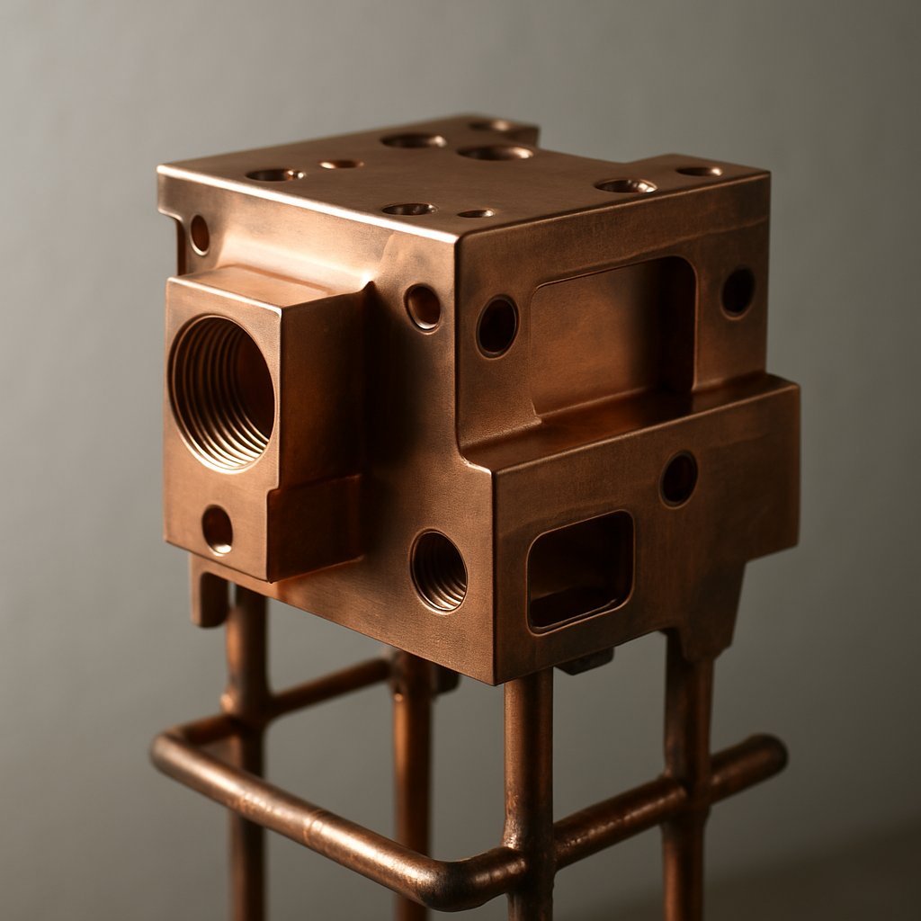
Copper Plating Thickness and Coverage Design Rules
Fit problems often start with a perfectly reasonable drawing note. The note says to plate copper to a target thickness, but the part geometry quietly changes how that deposit actually builds. When you copper electroplate a part, the coating adds dimension, and that added metal rarely lands evenly across every face, edge, recess, and thread.
Plan copper plating thickness into the part tolerance stack from the start. If plating is treated as an afterthought, tight fits, threads, and critical diameters can drift out of spec even when the shop meets the plating callout.
Planning Copper Thickness for Fit and Function
Guidance on design affects finishing thickness makes one point clear: almost every finish changes part dimensions, sometimes enough to matter a great deal. Electroplating theory says deposited metal rises with amp-minutes, but that relationship is only a guideline. Bath efficiency, part shape, and current distribution still change the real result, which is why trial runs and thickness testing are often needed on critical parts.
That matters most on features with little tolerance room. A broad flat surface may accept the deposit with no functional issue. A close-fitting shaft, a threaded hole, or a mating electrical face may not. The same nominal thickness target can behave very differently on a sharp corner than on a recessed wall.
Geometry Risks That Cause Uneven Copper Deposition
Electroplating current does not spread uniformly. The same source notes that shape, racking method, anode placement, and distance from the anode can shift local current density dramatically. In practice, high-current areas such as sharp edges, protrusions, and stud ends build thicker deposits. Low-current areas such as inside corners, grooves, blind holes, and long internal surfaces tend to plate thinner.
Hole behavior can be especially tricky. Through-holes may plate enough to affect fit, while blind holes can trap solution and fail to build as intended. Threads follow the same logic. If the threaded feature must remain functional after plating, the print should make that clear before the lot is released. Local current density matters too. Pushed too high, deposits can become burnt, powdery, dull, or frosty. Too low, and the finish may stay dull or may not form properly.
Masking Rack Points and Selective Coverage Considerations
Electroplating masking becomes essential when some areas must stay bare. Threads, screw holes, and certain contact zones may need protection to preserve fit or function. Good masking also helps prevent bleed under edges and unwanted build-up in no-plate zones. For selective copper plating, clean boundary lines and protected features should be defined before tooling and fixturing are chosen.
- Put copper plating thickness into the drawing tolerance stack, not into a late process note.
- Identify critical surfaces and where minimum thickness must actually be achieved.
- Expect heavier build on edges, corners, stud tips, and other exposed high-current areas.
- Expect lighter coverage in recesses, blind holes, inside corners, grooves, and long bores.
- Flag threads, holes, and tight-fit diameters for masking, oversize machining, or selective copper plating.
- Review rack orientation and contact-point locations on any functional face, because fixturing affects current flow.
- Run trials on unfamiliar geometry before locking production dimensions.
A copper callout becomes much more reliable when it also defines where thickness matters and how coverage will be judged. Without that detail, sourcing teams and platers can both believe they are right and still disagree at inspection.
Copper Plating Standards, Inspection, and Quality Control
A thickness note can be perfectly reasonable and still create trouble if the referenced document is vague, old, or misunderstood. In copper plating services, ASTM, MIL, and AMS callouts only work when the buyer, drawing owner, and plater are all reading the same requirement in the same way.
How to Read ASTM, MIL, and AMS Copper Callouts
Start with plain questions. What document is actually controlling the part. Which revision is active. Is copper the final finish or only an underplate. Is there a class, thickness range, or special inspection note on the drawing. PMPA points out that a complete plating note should state whether dimensions apply before or after plate, define minimum and maximum thickness, identify where thickness will be checked, list required tests, and clarify finish appearance when it matters. The same guidance also warns that blind holes and rack contact locations should be called out when they affect acceptance.
Legacy references deserve extra caution. If a print mentions astm b700 or mil-c-15726, do not assume everyone interprets those notes the same way. Confirm the exact document scope, revision status, and any customer-specific overrides before release. For aerospace-style copper callouts such as AMS 2418, published summaries emphasize thickness, adhesion, surface finish, and purity. MIL-C-14550 summaries similarly highlight thickness class, adhesion, finish quality, and documentation.
Inspection Checks That Matter Before Shipment
Inspection should follow the drawing, not shop habit. The AMS 2418 material describes non-destructive thickness checks such as eddy current or beta backscatter. MIL-C-14550 guidance also identifies XRF as a common thickness verification method and describes adhesion checks such as peel or bend style testing, depending on part requirements. Visual review still matters. Pits, scratches, roughness, uneven deposit, staining, or exposed base metal can trigger rejection even when thickness passes. Some programs may also require corrosion, conductivity, hardness, or surface-finish checks if the governing document or end use calls for them.
| Standard reference | What the buyer should confirm | Why it matters |
|---|---|---|
| Customer drawing and any ASTM callout | Exact document title, active revision, finish type, class or thickness, and sampling method | Prevents quoting and inspecting to the wrong requirement |
| AMS 2418 | Substrate, thickness requirement, adhesion criteria, finish expectation, and inspection method | Aligns aerospace-oriented process control with release criteria |
| MIL-C-14550 | Thickness class, measurement locations, defect limits, test method, and certification needs | Reduces mismatch between military-style callouts and supplier capability |
| Legacy notes such as astm b700 or mil-c-15726 | Whether the callout is still current, how the customer interprets it, and whether an internal spec supersedes it | Avoids sourcing delays, rework, and disputes over obsolete or inherited notes |
Avoiding Specification Mismatch in Copper Plating
One practical habit helps more than any single test: ask the plater to review the drawing note line by line before the PO is released. That conversation should cover scope, revision, thickness location, adhesion check, appearance standard, and evidence required at shipment, such as inspection data or a certificate of compliance. On paper, that looks like quality control. In production, it quickly becomes a supplier-selection issue, because prototype support and full-rate manufacturing do not manage documentation and repeatability in the same way.

Prototype vs Production Copper Plating Services
A shop that handles one urgent sample well may still be the wrong fit for a controlled launch. That gap matters in copper plating services because the same finish note can support very different goals depending on whether the part is still being learned or already approved for use.
Prototype Priorities in Copper Electroplating Services
Early builds are usually meant to answer questions. Prototype parts are used for design validation, fit checks, and functional testing, often with quick-turn methods and flexible setups. In prototype copper plating, buyers usually need speed, practical masking options, and feedback that helps engineering judge whether the requested finish can scale. If a supplier points out that a sample will show rack marks on a non-critical face, or that a temporary substrate is not production-intent, that is valuable manufacturability input.
What Changes When Programs Move to Production
Production parts serve end use, so expectations tighten. The same reference contrasts them with prototypes by emphasizing final-grade materials, larger volumes, stronger quality assurance, and traceability. In automotive work, IATF 16949 supports a system built around continuous improvement, defect prevention, and core tools such as APQP, PPAP, FMEA, MSA, and SPC. That changes what production copper plating looks like in practice: more stable fixturing, documented inspection, controlled revisions, formal change management, and repeatable throughput. A shortcut that is acceptable on ten samples may not be acceptable on saleable vehicle parts under APQP and PPAP.
How to Evaluate an Integrated Copper Plating Services Partner
Supplier structure changes the workload on your team. If the part still needs stamping, machining, surface treatment coordination, and launch planning, a single-source model can reduce handoff risk. For automotive components, Shaoyi is one resource worth reviewing because it combines high-precision stamping, CNC machining, custom surface treatments, rapid prototyping, and high-volume production for automakers and Tier 1 suppliers, backed by 15 years of experience and an IATF 16949 quality framework. Buyers should still confirm substrate compatibility, finish stack, validation needs, and exact process fit for their own parts.
| Service model | Upstream part making | Surface treatment coordination | Quality systems | Prototype support | Scale-up readiness |
|---|---|---|---|---|---|
| Shaoyi, integrated automotive partner | Supports stamping and CNC machining in one source | Coordinates custom surface treatments with part manufacturing flow | Operates under an IATF 16949 framework for automotive work | Offers rapid prototyping and early manufacturability feedback | Can support movement from samples to high-volume programs, subject to part and process fit |
| Plating-only supplier | Usually depends on buyer-supplied parts or outside fabrication | Often focused on the plating step rather than full part workflow | Capability varies by shop, industry focus, and documentation depth | Can be effective for short-run finish trials when the base part is already defined | May require added supplier coordination for launch, traceability, and volume ramp |
Those differences are not just operational details. They shape what information belongs in the RFQ, which is why vague sample requests often become expensive production problems later.
Building a Better Copper Plating RFQ
Many quote delays have nothing to do with price. They happen because the supplier is forced to guess what the copper layer is meant to do. A solid copper plating RFQ gives process intent, inspection intent, and handling intent in one package.
What to Include in a Copper Plating RFQ
- Base material - List the exact substrate, alloy, or resin, not just "metal".
- Drawing revision - Send the active print and any customer-specific notes.
- Required specification - Name the governing document and revision. If the print still calls out MIL-C-14550, note that DLA Quick Search lists it as canceled and superseded by SAE AMS2418. If legacy notes such as mil-t-10727 appear, ask the supplier how they will interpret them before release.
- Finish role - State whether copper is the final finish or an underplate below nickel, tin, silver, or gold.
- Thickness requirement - Give the target thickness and the critical measurement locations.
- Masking needs - Mark no-plate areas, threads, holes, rack-sensitive faces, and selective zones.
- Quantity - Clarify sample, pilot, service, or production volume.
- Program stage - Say whether the job is prototype or production, because fixturing, sampling, and documentation can change.
- End-use environment - Describe exposure to moisture, heat, vibration, current, or corrosive media.
- Inspection and paperwork - Define thickness method, adhesion check, appearance acceptance, and any certification needs.
- Packaging expectations - Call out separation, anti-tarnish needs, labeling, and transit protection.
Which Variables Change Scope Lead Time and Cost
- Complex geometry, recesses, and mixed-thickness areas.
- Selective plating and detailed masking.
- Tight thickness sensitivity on fit-critical features.
- Extra handling to prevent scratches, stains, or part-to-part contact.
- Coordination with upstream stamping, machining, or assembly.
- Rack versus barrel process choice, since part size and quality demands affect the method.
Next Steps for Sourcing Copper Plating Services
Before the PO is released, ask the supplier to restate the finish stack, thickness check points, and shipment criteria in writing. That single step catches inherited notes, unclear assumptions, and mismatched inspection plans early.
Automakers and Tier 1 suppliers that want a one-stop manufacturing resource can review Shaoyi. Its capabilities include stamping, CNC machining, rapid prototyping, custom surface treatments, and high-volume automotive support under an IATF 16949 framework. Even with an integrated partner, the safest path is still the same: verify process fit against your exact substrate, specification, and service environment before launch.
Frequently Asked Questions About Copper Plating Services
1. What are copper plating services typically used for?
Copper plating services are commonly used to add a controlled copper layer for electrical conductivity, solderability, surface leveling, dimensional build-up, or as a base under finishes such as nickel, tin, silver, or gold. In some applications copper stays exposed as the working surface, while in others it mainly supports the performance of the next plated layer. The best use depends on the part material, the service environment, and whether the drawing treats copper as a final finish or an underplate.
2. How do I choose between acid copper, alkaline copper, and electroless copper plating?
Start with the substrate and the purpose of the deposit. Acid copper is often chosen when the surface is already compatible and the goal is conductive build or smoothing. Alkaline copper or a copper strike is often considered when initial adhesion on active metals is the bigger concern. Electroless copper is usually more suitable for nonconductive parts or complex shapes where more even coverage matters more than fast, heavy build.
3. Is copper better as a final finish or as an underplate?
Copper can work in either role, but the choice should match the part's real job. As an underplate, copper is often valued for conductivity, leveling, and support for later finishes that need better wear, corrosion resistance, or cosmetic stability. As a final finish, it can make sense when conductivity, solderability, ductility, or economical build-up matter most. If the part will face a demanding environment or long-term appearance requirements, another outer finish may be the safer choice.
4. What information should be included in a copper plating RFQ?
A strong RFQ should identify the exact base material, drawing revision, required specification, thickness target, critical measurement locations, masking zones, and whether copper is the final finish or part of a finish stack. It should also state quantity, prototype or production status, end-use exposure, inspection method, paperwork needs, and packaging expectations. This helps the supplier choose the right preparation, fixturing, process route, and release plan before the order is placed.
5. What should automotive buyers look for in a copper plating services partner?
Automotive buyers should check process fit first, then review repeatability, documentation control, prototype support, inspection capability, and scale-up readiness. If a project also involves stamping, machining, or coordinated surface treatments, an integrated partner can reduce handoff risk. For automakers and Tier 1 suppliers, Shaoyi is one option to review because it combines high-precision stamping, CNC machining, rapid prototyping, custom surface treatments, and volume support under an IATF 16949 framework, but the exact copper plating route still needs to be confirmed against the specific part, substrate, and validation plan.