 Small batches, high standards. Our rapid prototyping service makes validation faster and easier —
  EN
EN


What Is CNC Milling Machine? The Choices That Shape Cost And Accuracy
What Is a CNC Milling Machine?
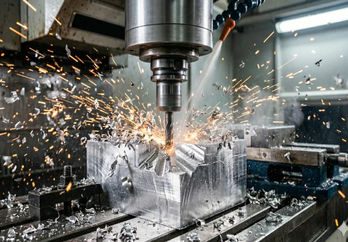
If you searched for what is cnc milling machine, the simplest answer is this: it is a mill that uses computer control to move along programmed axes while a rotating cutting tool removes material from a solid workpiece. In plain shop language, the machine does the motion precisely, and the cutter does the cutting.
A CNC milling machine is a computer numerically controlled machine that shapes parts by moving a rotating cutting tool and the workpiece along programmed axes to remove material.
What a CNC Milling Machine Actually Is
When people ask what is a cnc milling machine, they often mean the whole physical unit, not just the cutting method. That matters. A CNC mill is an actual machine with a spindle, table, axes, and controller working together. It is commonly used to make brackets, housings, plates, and fixtures from metal, plastic, or composite stock. If you are wondering what is cnc milling, think of it as the cutting action performed by that machine.
- The tool rotates and cuts material away.
- The machine follows programmed X, Y, and Z movements.
- The workpiece is usually held in place on a table or fixture.
- The result is a repeatable part shape, not a hand-guided cut.
How CNC Milling Fits Into Machining Definition
A quick mill machine definition helps clear up the jargon. Milling is one kind of machining. Machining is the broader category for controlled material removal processes. Milling uses a rotating cutter. Turning usually rotates the workpiece instead. So when someone asks what's milling, the accurate answer is not "all CNC work," but one specific machining method within the larger CNC field. A machining center is usually a more automated version of a CNC mill, often defined by having an automatic tool changer and tool magazine, as noted by J&M Machine Tools.
Why the Machine Matters More Than the Buzzword
Search terms can blur the picture, but the machine itself determines what can be cut, how accurately it repeats, and how much setup effort the job needs. That is why the names on the casting, the spindle arrangement, the table, and the control architecture matter more than a loose label. Those physical building blocks are where cost, stability, and accuracy start to separate one CNC mill from another.
Inside a Computer Numerical Control Milling Machine
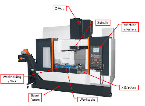
Those physical building blocks are where the story gets practical. A computer numerical control milling machine is not just a box that follows code. It is a stack of mechanical and control systems that must stay stable, move smoothly, hold tools securely, and manage heat and chips while cutting. Guidance from Protolabs and CNC Cookbook keeps pointing to the same truth: rigidity, motion control, backlash, and chip handling strongly shape output quality.
Core Parts of a CNC Mill
Many beginners can name the spindle, but the full list of parts of a cnc mill matters more than any single item. The spindle rotates the cutter. The tool holder or collet grips that cutter. The tool changer swaps tools automatically. The table and saddle carry the workpiece through programmed movement. The column and frame support the whole machine and help absorb vibration. The controller reads programmed instructions and sends commands to the motors and drives. Guideways direct axis travel. Coolant delivery reduces heat and helps flush chips away. The enclosure helps contain chips and coolant. A probe or tool setter helps locate part zero or measure tool length. Workholding, such as a vise or fixture, keeps the part from shifting under cutting forces.
What the Spindle Table and Controller Do
Think of the spindle as the machine's power source at the cut, the table and saddle as the moving platform, and the controller as the coordinator. In real cutting, small weaknesses compound fast. A poor tool holder can let the tool move slightly, which hurts finish and repeatability. Weak workholding can let a plate chatter. Poor coolant aim can leave chips recutting instead of clearing. On many cnc mills, daily performance depends less on brochure terms and more on how well these basic assemblies work together.
| Component | Job | Practical effect on machining results |
|---|---|---|
| Spindle | Rotates the cutting tool | Affects surface quality, material removal, and cut stability |
| Tool holder or collet | Clamps the tool in the spindle | Influences runout, tool security, and finish consistency |
| Tool changer | Loads different tools automatically | Reduces setup effort and supports more complex parts |
| Table and saddle | Support and move the workpiece | Affects positioning, access to features, and repeatability |
| Column and frame | Provide structure and stiffness | Reduce vibration and chatter for better accuracy |
| Controller | Interprets the program and coordinates motion | Improves consistency when executing toolpaths and offsets |
| Motors, drives, and feedback system | Move the axes and monitor commanded motion | Support smooth travel and repeatable positioning |
| Guideways | Guide axis movement | Influence friction, smoothness, and backlash-related behavior |
| Coolant delivery | Cools the cut and clears chips | Helps tool life, finish quality, and chip evacuation |
| Enclosure and chip management | Contain debris and direct chips away from the cut | Reduce chip interference and keep operation cleaner |
| Probe or tool setter | Measures tool length or locates part zero | Reduces setup variation and improves first-part confidence |
| Workholding | Secures the part during cutting | Prevents movement, protects alignment, and supports accuracy |
How Machine Architecture Affects Accuracy
This is where cnc milling components stop being labels and start becoming cost drivers. CNC Cookbook notes that rigidity is baked into the machine early, while backlash and friction can limit how faithfully motion is repeated. In simple terms, a stiffer frame, steadier guideway system, and well-controlled axis motion usually give the machine a better chance of holding position and resisting chatter. That is why heavier, more rigid machines often behave differently from light-duty equipment, even before tooling and programming enter the picture.
- Check frame and column rigidity first if accuracy matters.
- Look closely at spindle and toolholder quality for finish and vibration control.
- Pay attention to guideways, drives, and feedback for repeatable motion.
- Do not treat workholding and probing as accessories. They affect setup time and part consistency.
- Coolant delivery and chip control matter every day, especially on longer runs.
A machine can have excellent hardware and still produce poor parts if the tools, offsets, and program are not prepared correctly. That handoff from machine anatomy to actual execution is where milling becomes a workflow, not just a machine description.
How the CNC Milling Process Works
A rigid machine matters, but parts are made through a workflow, not hardware alone. If you are asking how does a cnc machine work in real production, picture a controlled handoff from design software to machine motion. CAD defines the part. CAM plans the cuts. G-code carries the instructions. The controller, tooling, workholding, and operator turn those instructions into a physical component. That full chain is the cnc milling process, and it is where cost, accuracy, and scrap risk start to separate.
From CAD Model to G Code
- Create the CAD model. The job starts as a 2D drawing or 3D model with holes, pockets, faces, and critical dimensions. As JLCCNC notes, common export formats for CNC work include STEP, IGES, and DXF, depending on whether the part is primarily 3D or 2D.
- Move the model into CAM. CAM software does not redesign the part. It decides how to machine it by assigning operations, cut order, toolpaths, and tool approach.
- Select tools and cutting strategy. End mills, drills, and ball nose tools are chosen to match the material and geometry. Poor tool access, overly deep pockets, or mismatched tooling can cause trouble before the machine even starts.
- Generate and simulate G-code. CNC machines do not read CAD files directly. CAM converts the plan into G-code, then simulation helps catch collisions, missed features, and unsafe moves early.
- Prepare the raw stock. Material is cut to a workable size and checked for flatness and stability so the setup begins from a reliable base.
What Happens During CNC Milling Machine Operation
- Set up the machine. The operator homes the axes, loads tools, mounts the stock, and sets tool offsets and work zero.
- Secure and align the part. Workholding is not just a clamp-and-go step. The workholding guide explains that poor positioning, uneven clamping, or part deformation can affect dimensions, alignment, and surface finish, especially on tighter-tolerance work.
- Run a dry check. Many shops verify the path above the part first to confirm clearance, fixture safety, and correct zeroing.
- Cut in stages. Roughing removes bulk material, semi-finishing refines the shape, and finishing produces final surfaces and edges.
- Check during the cut. Operators watch chip flow, coolant delivery, tool wear, sound, and part stability. In-process checks help catch drift before a full batch is affected.
If you have searched cnc machine how it works, the short answer is simple: the controller reads G-code line by line, commands axis motion, calls the correct tool, and follows the programmed path while the spindle removes material. In practice, the machining milling process stays accurate only when that digital plan matches the real setup on the table.
Inspection and Finishing After Cutting
- Inspect the part. Critical features are checked with tools such as calipers, micrometers, or a CMM, depending on the tolerance and geometry.
- Deburr and finish. Burrs, sharp edges, and visible tool marks are removed. If the application requires it, the part may also be polished, coated, or heat treated.
- Review the setup reality. If the job needed awkward re-clamping, difficult chip control, or limited side access, that is a sign the milling machine process may benefit from a different machine layout.
Seen this way, the cnc milling process is not a single cutting event. It is a chain of design, planning, fixturing, cutting, and verification. And once part geometry starts pushing visibility, chip evacuation, or multi-side access, machine format becomes a practical decision instead of a catalog detail.
Types of CNC Milling Machines Compared
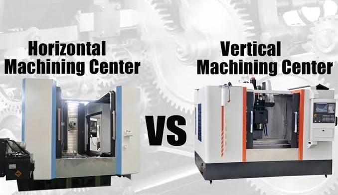
When part geometry starts demanding better side access, cleaner chip flow, or fewer re-clamps, machine format stops being a background detail. It becomes a real production decision. Common types of cnc milling machines include vertical, horizontal, bed, gantry, and multi-axis formats, but most buyers first narrow the choice by asking two practical questions: Is the spindle vertical or horizontal, and is the machine benchtop or industrial?
Vertical and Horizontal CNC Mills
Among the most common cnc mill types, the vertical machine is the familiar starting point. A vertical machining center places the spindle above the table, which gives clear visibility of the cut and simple top-down access for vises and flat fixtures. Productivity Inc notes that vertical machines are often a good fit for varied work, smaller batches, and simpler 3-axis parts. In everyday shop use, a vertical milling cnc layout works well for plates, brackets, and many prismatic parts.
A horizontal machine changes the spindle orientation, and that changes the job itself. In cnc horizontal milling, gravity helps chips fall away from the cutting zone, which is especially useful in deeper cavities and multi-face work. Horizontal machines also commonly pair with tombstones, pallet systems, and 4-axis positioning, so several sides of a part can often be reached with fewer manual setups. The tradeoff is a larger footprint, more involved fixturing, and a bigger investment.
A simpler vertical machine is often enough for general-purpose, top-access work. A horizontal format earns its place when chip evacuation, multi-face access, and throughput start driving the economics.
Benchtop and Industrial Milling Machines
Size changes the outcome too. CNC Cookbook emphasizes that rigidity is built into the machine, and larger accurate machines become heavier for a reason. Benchtop mills are easier to place and budget for, but their lighter structure usually means a smaller work envelope, less damping, and more sensitivity to vibration. They are often better matched to learning, prototyping, and lighter-duty work in plastics, wood, aluminum, or small parts.
Industrial machines trade space and cost for stiffness, stronger repeatability expectations, larger envelopes, and better automation potential. That can include automatic tool changing, probing, pallet handling, and longer unattended runs. For steel, larger production parts, or repeat work where process stability matters every day, the heavier platform usually makes the difference.
| Machine format | Orientation | Footprint | Setup style | Material range | Production fit |
|---|---|---|---|---|---|
| Vertical machining center | Vertical spindle | Usually more compact | Direct top access, vises and flat fixtures, often more re-clamping on multi-face parts | Broad general-purpose range for metals, plastics, and composites | High-mix work, short runs, simpler 3-axis parts |
| Horizontal machining center | Horizontal spindle | Usually larger | Tombstones, pallets, and multi-face fixturing with fewer manual setups | Broad range, especially useful where heavy chip load and tougher materials are involved | Repeat production, multi-side components, higher throughput focus |
| Benchtop CNC mill | Usually vertical | Smallest | Simple manual setups and compact workholding | Best suited to lighter-duty work and smaller parts | Learning, prototyping, occasional short-run work |
| Industrial CNC mill | Vertical or horizontal | Larger and heavier | Supports dedicated fixtures, tool changers, probes, and automation | Wide material capability, including demanding metal applications when machine rigidity supports it | Production use, repeatable quality, tighter process control |
Which Machine Size Fits the Job
Choose by part family, not by marketing labels. If the work is mostly plates, housings, brackets, or fixtures with easy top access, one of the simpler machine formats may be the smartest answer. If parts need multiple faces, better chip evacuation, or fewer setups to stay profitable, machine layout matters more than catalog simplicity. That is also where another question starts to surface: not just what format the mill has, but how many axes it can move at once.
Why Extra Axes Matter in a CNC Mill Machine
Spindle orientation tells you how a machine is arranged. Axis count tells you how the cutter or part can move inside that arrangement. On a cnc mill machine, that difference quickly affects setup count, tool access, fixture design, and cost. Material from Prototek, CloudNC, and MakerVerse points to the same pattern: more axes mainly buy better access and fewer manual re-clamps, but they also raise machine, programming, and setup demands.
How 3 Axis Milling Works
In cnc 3 axis milling, the tool moves in X, Y, and Z. The workpiece stays fixed in one setup while the spindle approaches from the available direction. This is the standard choice for prismatic parts such as plates, brackets, housings, and fixtures. It handles pockets, faces, holes, and many common contours well. Even a basic 3d milling machine in 3-axis form can machine accessible 3D surfaces, but only where the tool can reach without tilting. The limitation shows up on multi-side parts or angled features, where the part usually has to be removed and fixtured again.
When 4 Axis Adds Real Value
4-axis keeps the three linear motions and adds one rotational axis, usually the A-axis around X. That lets the workpiece rotate so different sides can be machined with less manual repositioning. CloudNC describes two common approaches: indexed 4-axis, where the part rotates to a fixed angle before cutting, and continuous 4-axis, where rotation happens during cutting for wrapped or helical features. This is where cnc machine milling often becomes more efficient for multi-side components, cylindrical forms, and parts that would otherwise need several fixtures.
Why 5 Axis Changes Part Strategy
5-axis combines X, Y, and Z with two rotational axes. Depending on the machine, the tool or the workpiece can tilt and rotate to reach compound angles and complex surfaces. The references distinguish between indexed 3+2 positioning and fully continuous 5-axis cutting. In practical terms, 5-axis is valuable when part geometry would force awkward re-clamping on simpler machines. It can reduce fixture complexity and improve access to deep or highly contoured areas, but the tradeoff is higher machine cost and more advanced programming and verification.
| Axis count | Ideal part shapes | Repositioning needs | Complexity level | When paying for more capability makes sense |
|---|---|---|---|---|
| 3-axis | Prismatic parts, flat faces, pockets, drilled features, accessible contours | Highest for multi-side work, since parts often need to be re-fixtured | Low to moderate | Best when features are reachable from simple setups and fixture cost must stay low |
| 4-axis | Multi-side components, cylindrical parts, wrapped features, helical forms | Lower than 3-axis because the part can rotate to new faces | Moderate to advanced | Worth it when fewer setups improve consistency or when rotation unlocks features a 3-axis setup handles poorly |
| 5-axis | Complex surfaces, compound-angle features, intricate cavities, high-access geometries | Lowest in many cases because more faces and angles can be reached in one overall setup strategy | Advanced | Makes sense when geometry, access, or tolerance relationships across faces justify the extra machine and programming cost |
More axes are not automatically the right answer. If the part is straightforward and easy to fixture, 3-axis may still be the smartest option. If side access or wrapped geometry drives the job, 4-axis can be the practical middle ground. If the design depends on compound angles or flowing surfaces, 5-axis may simplify the whole plan. That is why axis count matters in cnc machine milling, but it is still only one part of process selection. A multi-axis mill remains a milling system, not a substitute for turning, drilling, or routing when another process fits the shape better.
CNC Milling Compared With Similar Processes
More axes give a mill better access, but they do not make milling the best answer for every part. Much of the confusion behind searches like cnc vs milling machine comes from comparing a control method with a specific cutting operation. CNC machining is the broader category of computer-controlled material removal. Milling is one process inside that category. Material from Northeast Precision and RapidDirect points to the same distinction: a cnc manufacturing process might be milling, turning, drilling, or another subtractive method depending on the part.
CNC Milling Versus CNC Machining
A useful plain-language rule is this: CNC tells you how the machine is controlled, not what exact cut it performs. In cnc machining milling, the second word names the actual operation. Milling uses a rotating cutter against a mostly fixed workpiece to make flats, pockets, slots, holes, and many prismatic 3D features. CNC machining can include milling, but it can also include turning, drilling, grinding, and other operations. So milling is specific, while CNC machining is the umbrella term.
Milling Compared With Turning Drilling and Routing
Geometry usually settles the choice faster than terminology. For many cnc milling turning decisions, the key question is simple: does the tool spin, or does the part? Turning rotates the workpiece and is usually the better fit for shafts, bushings, and other cylindrical shapes. Drilling focuses on making holes. Routing also uses a rotating tool, but the machine is typically lighter and better suited to softer materials such as wood, foam, and many plastics rather than rigid metal cutting.
| Process | Tool motion | Workpiece motion | Ideal parts | Limitations |
|---|---|---|---|---|
| CNC machining | Varies by operation | Varies by operation | Jobs needing one or more automated subtractive operations | Too broad to describe one cutting method by itself |
| CNC milling | Rotating cutter moves along programmed axes | Usually fixed in a vise or fixture | Brackets, housings, plates, fixtures, and other prismatic parts | Less efficient for mostly round parts, and tool access can become limiting |
| CNC turning | Tool feeds along the part | Workpiece rotates in a chuck | Shafts, pins, bushings, and other cylindrical components | Poor fit for flat-sided or highly irregular shapes |
| CNC drilling | Rotating drill advances along the hole axis | Usually fixed | Initial hole creation | Not the best standalone choice when hole size, alignment, or finish needs refinement |
| CNC routing | Rotating cutter on a lighter, faster machine | Usually fixed sheet or panel | Wood, foam, plastics, and some composite trimming | Lower rigidity and lower precision for demanding metal work |
No single cnc manufacturing process wins by default. The part shape, material, and finish requirement decide which one works efficiently.
Manual Milling and Numerical Control Differences
Manual milling and CNC milling both remove material with a rotating cutter, but control is the dividing line. Taig Tools describes manual mills as operator-driven, with handwheels and real-time adjustments, while CNC mills use numerical control to follow programmed coordinates automatically. Manual milling often makes sense for repair work, quick one-off parts, or immediate dimension changes. CNC is stronger when repeatability, batch consistency, and complex geometry matter more than on-the-fly adjustment.
- Choose turning instead when the part is mainly round and symmetric.
- Choose drilling or follow-on hole processes when the job is mostly hole-making.
- Choose routing when the material is soft sheet stock and speed matters more than metal-cutting rigidity.
- Choose manual milling when fast hand adjustments matter more than repeat production.
- Do not force milling onto a part just because it is a familiar process.
Process choice is only half the story. A part can be perfectly matched to milling on paper and still become difficult or expensive because of deep pockets, weak walls, poor tool access, or unrealistic finish expectations.
Design Rules for CNC Precision Milling
A part can be technically millable and still be expensive to produce. In everyday shop work, geometry, material, and finish requirements often decide whether the job runs smoothly or turns into a slow, delicate setup. That manufacturability lens matters because it connects the machine's capability to real cost, quality, and repeatability.
How Design Choices Affect Milling Difficulty
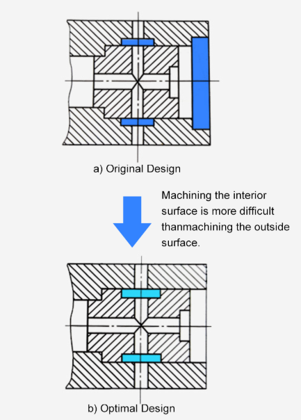
Planning guidance from Cast Technologies keeps returning to the same point: efficient milling starts with part and process planning, proper tooling, stable workholding, and toolpaths that support chip evacuation and consistent cutting. In practice, an open bracket or flat plate is usually easier to machine than a housing with deep pockets, thin walls, and limited clamping space. The same pattern shows up in molds, fixtures, and metal production parts. If a feature is hard to reach, hard to support, or hard to clear of chips, it is usually harder to machine well.
- Keep tool access open where possible. Deep, narrow pockets make tool reach and chip evacuation more difficult.
- Leave solid areas for clamping and fixturing. Stable, repeatable workholding helps accuracy and reduces vibration.
- Use realistic inside corners. Milling tools are round, so sharp internal corners often add extra effort.
- Avoid walls so thin that they can flex under cutting or clamping forces.
- Match the design to the part family. Plates and brackets are often simpler than enclosed housings or cavity-heavy molds.
Good milled parts are designed for tool access and fixturing, not only for clean-looking CAD.
Materials Tolerances and Surface Finish
The milling machine material changes the plan too. A job centered on metal cnc milling or cnc milling metals often asks more of rigidity, tooling, and process stability than cnc plastic milling. That does not make plastic parts automatic. It simply means the cutting behavior, chip control, and finish strategy are different. The same geometry may feel routine in one material and much more demanding in a cnc steel milling machine setup.
Finish and tolerance requirements can also raise cost even when the shape stays the same. 3DS lists a standard as-machined surface roughness of about 3.2 μm. With an added finishing pass, roughness may drop to 1.6, 0.8, or even 0.4 μm, but those extra passes add production cost. The same source notes that bead blasting can remove tool marks and create a satin or matte look, yet it also removes surface material, so critical features may need masking. For aluminum and titanium parts, anodizing adds protection, with Type II coatings up to 25 μm and Type III up to 125 μm.
When Milling Is the Right Process
Milling is often the right choice when a part needs flat surfaces, pockets, slots, holes, and repeatable locating features. That makes it a strong fit for housings, brackets, fixtures, and many prismatic components. It becomes less attractive when extreme tool reach, weak workholding, or demanding finish requirements force too many extra steps. At that point, cnc precision milling is not just a machine question. It is a decision about how the part should be designed, inspected, and sourced. Those same realities also shape whether it makes more sense to build this capability in-house or rely on outside production support.
How to Choose a CNC Milling Machine or Partner
A part can be perfectly suited to milling and still leave one business decision open: build the capability yourself or buy it from a supplier. That choice starts with plain questions buyers actually ask, such as what is a milling machine used for in your workflow, what do milling machines do that your current shop cannot, and which cnc machine uses truly justify the investment.
How to Choose a CNC Milling Machine
- Match machine size to the real job. Good machine selection starts with size, but usable capacity is also limited by tool reach, setup height, and tool-change clearance, not only axis travel.
- Check spindle and tooling fit. Spindle speed matters, but so do holder type, cutter compatibility, and the materials you plan to run every day.
- Judge complexity, not just dimensions. Protomatic notes that multi-face parts and tighter geometric relationships may justify 4-axis or 5-axis equipment because fewer setups can reduce compounded positioning error.
- Review automation options early. Tool changers, probing, pallets, and unattended running only pay off if your part mix is repeatable enough to use them.
- Budget for the full cell. A solid cost analysis should include tooling, labor, floor space, maintenance, consumables, and inspection, not just the machine price.
- Test production volume and utilization. Hotean shows that break-even often depends more on spindle hours than sticker price, with formal make-or-buy review becoming especially worthwhile when outsourcing on one machine platform gets large enough to challenge in-house economics.
- Confirm quality requirements. If the work needs capability studies, SPC, PPAP, or automotive documentation, make sure the machine plan and the team around it can support that level of control.
When to Buy Capacity and When to Outsource
In purchasing terms, what is a cnc mill? It is a production asset that only makes sense when size, complexity, productivity, and utilization line up. Low volume, changing demand, or occasional specialty work often favor outsourcing. Steady repeat work, faster engineering feedback, and tighter day-to-day control can favor in-house capacity. That is also the practical answer to what does a milling machine do for a business: it creates value when the work is stable enough to support the system around it.
Using a Certified Machining Partner for Production
- Shaoyi Metal Technology: For automotive-grade external support, Shaoyi offers IATF 16949 certified custom machining with SPC-based quality control and support from rapid prototyping to automated mass production.
- Use outsourcing where it is strongest: overflow work, specialized multi-axis parts, launch programs, and jobs that do not justify a dedicated in-house machine.
- Choose by capability, not slogans: check material fit, tolerance control, inspection depth, delivery reliability, and whether the supplier matches your real cnc machine use.
Readers often ask what do milling machines do beyond cutting material. In business terms, the best cnc machine uses turn the right mix of geometry, quality, and volume into predictable output. Whether that happens on your floor or through a qualified partner should be a numbers-and-capability decision, not a guess.
Frequently Asked Questions About CNC Milling Machines
1. What is a CNC milling machine used for?
A CNC milling machine is used to make solid parts by cutting material away in a controlled, repeatable way. It is commonly chosen for brackets, housings, plates, fixtures, molds, and many production components in metal or plastic. It is especially useful when a part needs flat surfaces, pockets, slots, or accurately placed holes that would be difficult to produce consistently by hand.
2. How does a CNC milling machine work from design to finished part?
The workflow usually starts with a CAD model, then CAM software plans the cutting strategy and creates G-code. On the shop floor, the operator loads tools, secures the raw stock, sets work zero, and checks the program before cutting begins. The machine's spindle, table, and controller then work together to remove material in stages, followed by inspection, deburring, and any required finishing.
3. What is the difference between CNC milling and CNC machining?
CNC machining is the broad category for computer-controlled material removal, while CNC milling is one specific method inside that category. Milling uses a rotating cutter to shape a mostly fixed workpiece, making it a strong fit for prismatic parts and multi-feature surfaces. Other CNC machining methods, such as turning or drilling, use different machine motions and are often better for round parts or hole-focused work.
4. When is 3-axis enough, and when do you need 4-axis or 5-axis milling?
3-axis milling is often enough for straightforward parts that can be reached from simple directions, such as plates, brackets, and many housings. 4-axis becomes useful when several sides need machining with fewer re-clamps or when rotational access improves consistency. 5-axis is usually justified when a design includes compound angles, complex surfaces, or difficult tool access that would otherwise require multiple fixtures and more setup risk.
5. Should you buy a CNC milling machine or outsource milling work?
Buying makes sense when your production volume is stable, your part mix is predictable, and you can support programming, tooling, inspection, and maintenance in-house. Outsourcing is often the better choice for overflow capacity, launch programs, specialty multi-axis work, or jobs with demanding quality documentation. For automotive-grade production, a certified partner such as Shaoyi Metal Technology can be a practical option because it offers IATF 16949 custom machining, SPC-based quality control, and support from prototype runs to automated mass production.