 Small batches, high standards. Our rapid prototyping service makes validation faster and easier —

Coordinate Measuring Machine Stamping Inspection: Essential Guide
TL;DR
Coordinate measuring machine stamping inspection is a high-precision quality control process used to verify the dimensional accuracy of sheet metal parts against 3D CAD models. Unlike standard gauging, a CMM allows manufacturers to detect complex stamping defects such as springback, warping, and hole position errors with micron-level accuracy. This method is critical for validating compliance with Geometric Dimensioning and Tolerancing (GD&T) standards before mass production.
By using a coordinate measuring machine (CMM), engineers can analyze surface profiles and trimming lines that manual tools miss. This guide covers the technical implementation of CMM for stamped parts, how to interpret inspection reports, and when to choose CMM over 3D laser scanning.
The Role of CMM in Metal Stamping Quality Control
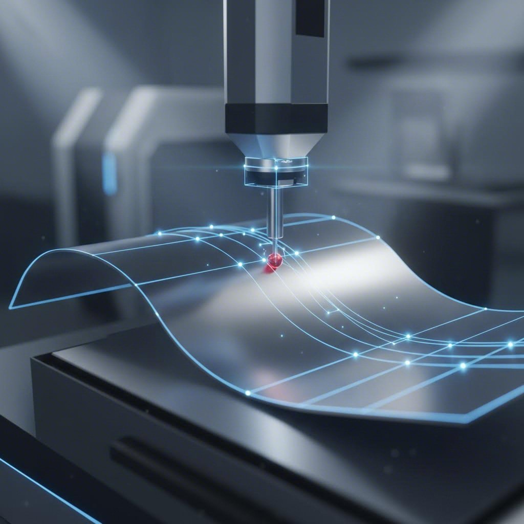
In the high-stakes world of automotive and aerospace manufacturing, stamped parts present unique quality control challenges. Unlike machined components, which are rigid and prismatic, stamped sheet metal is often flexible and subject to complex physical distortions. A coordinate measuring machine stamping inspection serves as the ultimate validation tool, bridging the gap between digital design and physical reality.
The primary function of CMM in this context is to quantify geometric characteristics that manual tools cannot measure reliably. Stamped parts often feature free-form surfaces and intricate curves that require 3D verification. According to Sinoway Industry, CMMs are essential for verifying "body-in-white" compatibility, ensuring that individual panels fit together perfectly during final assembly. Without this level of precision, minor deviations in hole pitch or surface profile can lead to catastrophic assembly failures.
Common Stamping Defects Detected
A robust CMM inspection protocol is designed to catch specific defects inherent to the cold-forming process. These include:
- Springback: The tendency of metal to return to its original shape after bending, causing deviation from the nominal CAD model.
- Hole Position Errors: Misalignments caused by punch shifting or material stretching during the press cycle.
- Trimming Line Deviations: Irregular edges resulting from worn dies or improper nesting.
- Surface Profile Errors: Warping or twisting that exceeds the specified profile tolerances.
By detecting these issues early, manufacturers can adjust their die designs and press settings before committing to high-volume runs, significantly reducing scrap rates and rework costs.
Technical Implementation: Alignment & Fixturing
Successfully measuring a stamped part requires more than just a calibrated machine; it demands a deep understanding of alignment physics. Sheet metal parts are often non-rigid, meaning their shape can change depending on how they are supported. This makes the holding fixture and alignment strategy critical for repeatable results.
RPS Alignment Strategy
For automotive parts, the Reference Point System (RPS) is the standard alignment method. As described by 3D-Scantech, RPS alignment uses specific features—such as holes, slots, or surface points—to lock the part into a coordinate system that mimics its final assembly position. This ensures that the measurement data reflects how the part will actually perform in the vehicle, rather than how it sits in a free state.
Constrained vs. Free State Measurement
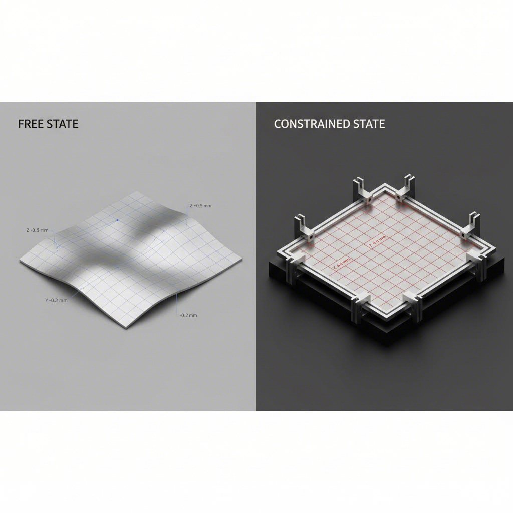
One of the most debated topics in CMM stamping inspection is whether to measure parts in a "free state" or "constrained state."
- Free State: The part is placed on the table with minimal support. This reveals the true, relaxed shape of the metal but can show deviations caused by gravity or residual stress.
- Constrained State: The part is clamped onto a dedicated fixture that simulates its installation environment. This is often required for flexible parts like door panels or hoods to verify they will meet specifications when bolted down.
Top-tier manufacturers, such as Shaoyi Metal Technology, leverage these advanced alignment and fixturing techniques to bridge the gap from rapid prototyping to high-volume automotive production. By adhering to strict standards like IATF 16949, they ensure that every control arm and subframe meets global OEM requirements, whether for a batch of 50 prototypes or millions of mass-produced units.
How to Read a CMM Inspection Report
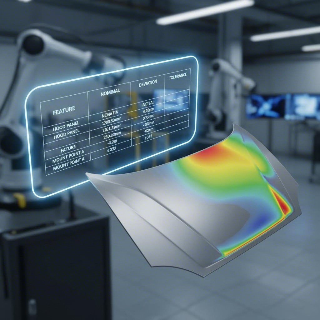
Interpreting the output of a CMM is a vital skill for quality engineers. A standard inspection report compares the Nominal (ideal) data from the CAD model against the Actual (measured) data from the physical part. Understanding the layout of these reports ensures you can quickly identify critical failures.
According to a detailed guide by GD Prototyping, a comprehensive report typically includes a header with part revision levels and a body containing line-by-line feature data. The most critical columns to analyze are the Deviation and Out-of-Tolerance (OUTTOL) fields.
| Column Name | Description | Action Required |
|---|---|---|
| Feature ID | Name of the measured element (e.g., Circle_1, Surface_A). | Verify it matches the print callout. |
| Nominal | The target dimension from the CAD model. | Reference value only. |
| Actual | The precise measurement taken by the probe. | Compare to Nominal. |
| Deviation | The difference: (Actual - Nominal). | Analyze for trends (e.g., tool wear). |
| Tolerance | The allowable range (e.g., +/- 0.05mm). | Define the pass/fail limit. |
| OUTTOL | Amount the feature exceeds tolerance. | Critical: Any non-zero value is a fail. |
When reviewing GD&T callouts, pay special attention to "Profile of Surface" and "True Position." For stamped parts, a surface profile deviation often indicates springback issues, while true position errors usually point to problems with the piercing die or locating pins.
CMM vs. 3D Laser Scanning for Stamping
While CMMs are the gold standard for precision, 3D laser scanning is gaining popularity for specific applications. Understanding the strengths of each technology helps in selecting the right tool for the job.
The Precision of Tactile CMM
Traditional tactile CMMs, using a touch probe, offer unmatched accuracy. Duggan Manufacturing notes that high-end CMMs are accurate to within 5 microns (0.005mm). This makes them the superior choice for inspecting critical features with tight tolerances, such as bearing bores or mounting holes where a single micron matters.
The Speed of Laser Scanning
In contrast, 3D laser scanners capture millions of data points in seconds, creating a dense "point cloud" or heat map. This is particularly useful for analyzing springback across a large surface, such as a car hood. The heat map provides an instant visual representation of where the part is high or low relative to the CAD model. However, scanning is generally less precise, with typical accuracies around 20 microns (0.02mm).
Decision Framework
- Use CMM When: You need to certify specific GD&T tolerances, measure hole diameters with high precision, or perform final inspection for critical mating features.
- Use Scanning When: You need to troubleshoot die shapes, visualize global warping/springback, or reverse engineer a physical part into a CAD model.
Conclusion
Coordinate measuring machine stamping inspection is not just a verification step; it is a diagnostic tool that drives process improvement. By accurately capturing data on springback, trim lines, and hole positions, manufacturers can fine-tune their stamping dies to achieve consistent quality. Whether using a tactile CMM for micron-level precision or 3D scanning for surface analysis, the goal remains the same: ensuring that every stamped part meets the rigorous demands of modern engineering.
For manufacturers navigating the complexities of automotive or aerospace supply chains, partnering with fabrication experts who understand these inspection protocols is essential. Correctly implemented, CMM inspection transforms raw data into actionable insights, securing the integrity of the final assembly.
Frequently Asked Questions
1. What is the difference between CMM and manual gauging?
Manual gauging, such as using calipers or check fixtures, provides quick checks for specific dimensions but is limited by human error and the inability to measure complex 3D curves. A CMM uses a computer-controlled probe to measure geometry in 3D space, providing higher accuracy and the ability to verify GD&T callouts like surface profile and true position.
2. How much does a CMM inspection cost?
The cost of CMM inspection varies significantly based on the complexity of the part and the equipment used. Portable CMMs can range from $10,000 to $150,000 for purchase, while outsourced inspection services are typically billed hourly. Factors influencing service cost include programming time, fixture requirements, and the number of features to be verified.
3. Why is RPS alignment important for stamped parts?
RPS (Reference Point System) alignment is crucial because stamped parts can flex. By aligning the part using the same datum points (holes/surfaces) that will be used in the final assembly, the CMM measurement simulates the part's installed state. This ensures that the data reflects functionality rather than just the part's shape in a free state.