 Small batches, high standards. Our rapid prototyping service makes validation faster and easier —

Solving the Most Common Issues with Progressive Dies

TL;DR
Common issues with progressive dies stem from three primary areas: misalignment, part quality defects, and tool degradation. Misalignment often results from incorrect pitch, progression, or pilot calibration, causing features to be formed out of location. Stamping defects like burrs, cracks, and wrinkles directly impact part quality and are typically caused by tool wear or improper process control. Finally, premature wear on die components accelerates these problems, leading to decreased precision and costly downtime.
Diagnosing Die Misalignment and Feeding Errors
Die misalignment and material feeding errors are among the most critical issues in progressive die stamping, as they create a cascade of failures throughout the process. The core problem is the failure to accurately locate and register the material strip at each station. When the strip's position is even slightly off, every subsequent operation—from piercing to forming—will be incorrect, leading to scrapped parts and potential die damage. This precise positioning is fundamental to the entire operation, and its failure undermines the high-speed, high-volume advantages of progressive stamping.
The most frequent cause of these errors is an incorrectly set pitch or progression, which is the distance the material strip advances between stations. According to an analysis by Dynamic Die Supply, if this distance or the pilot release timing is not perfectly calibrated, the die cannot register the strip correctly. This results in features like pierced holes being out of location. Pilot pins, which enter previously pierced holes to finalize the strip's position, are critical. These pilots must fit the hole with a tight tolerance that leaves little room for error. If the feeder releases the material at the wrong time, the pilots cannot engage properly, leading to misregistration.
Beyond feeder calibration, the physical components of the die play a vital role. Worn or damaged guide components, such as guide pins and bushings, can introduce play and allow the strip to shift. Similarly, improper pilot release calibration can cause the material to be held or released at the wrong moment, disrupting the smooth transfer between stations. An inexperienced operator might mistakenly try to adjust the forming stations themselves, when the root cause lies entirely within the material feeding and registration system. Correctly diagnosing these issues requires a systematic approach that starts with the material's entry into the die.
To effectively troubleshoot these alignment and feeding problems, operators should follow a structured checklist to isolate the root cause. This methodical process prevents unnecessary adjustments to die stations and focuses on the true source of the error.
- Verify Pitch and Progression: Measure the actual feed length and compare it to the die's design specification. Check for any improper adjustments in the feeder settings.
- Inspect Pilot Engagement: Ensure pilots are entering the prepierced holes smoothly and without sticking. Check for wear on the pilot pins and verify the clearance between the pilot and the hole is within tolerance.
- Calibrate Feeder Release Timing: Confirm that the feeder releases its grip on the material strip at the precise moment that allows the pilots to take over registration.
- Examine Guide Components: Inspect all guide pins, bushings, and rails for signs of wear, galling, or damage that could impede accurate strip movement.
- Check for Material Drag: Ensure there are no obstructions or unnecessary friction points preventing the strip from advancing smoothly through the die.
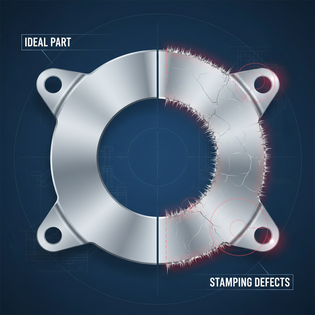
Identifying and Correcting Common Stamping Defects
Even with perfect alignment, the quality of the final stamped part can be compromised by a range of defects. These flaws are undesirable alterations to the part's geometry or surface finish, often signaling underlying issues with the tooling or process parameters. Identifying the specific type of defect is the first step toward diagnosing its cause and implementing an effective solution. Addressing these issues is crucial for maintaining part functionality, appearance, and overall quality control.
One of the most frequent defects is the formation of burrs—sharp, raised edges on the part. Franklin Fastener explains that burrs are typically caused by a dull cutting edge on the punch or die, or incorrect clearance between them. As the cutting edges wear down, they no longer shear the metal cleanly, instead tearing it and leaving a rough edge. This not only affects the part's quality but can also pose a safety hazard and interfere with subsequent assembly operations. Regular inspection and sharpening of tooling are essential preventative measures.
Other common defects include wrinkling, buckling, and tearing. Wrinkles often occur during drawing operations when there is insufficient blank holder force, allowing the sheet metal to flow uncontrollably into the die cavity. Conversely, if the holding force is too high or the material lacks sufficient ductility, it can lead to tearing or surface cracks as the metal is overstretched. The interplay between material properties, lubrication, and die pressures is delicate. A single root cause, such as selecting the wrong material grade, can manifest as multiple different defects, highlighting the importance of a holistic approach to troubleshooting.
For quick reference, the following table outlines common stamping defects and their primary causes, helping operators rapidly diagnose issues on the production floor.
| Defect | Common Cause(s) | Primary Solution |
|---|---|---|
| Burrs | Dull cutting edges; improper punch-to-die clearance. | Sharpen or replace tooling; adjust clearance. |
| Wrinkling / Buckling | Insufficient blank holder pressure; improper lubrication. | Increase blank holder force; adjust draw beads or lubrication. |
| Tearing / Surface Cracks | Excessive blank holder pressure; poor material ductility; sharp die radii. | Decrease holding force; change material; polish and increase die radii. |
| Mismatched Edges | Incorrect tool alignment; worn guide components. | Realign die components; inspect and replace guides. |
| Part Crushed / Deformed | Scraps or foreign material in the die; improper punch depth. | Clean the die; solve scrap removal issues; adjust punch depth. |
Preventing Premature Tool Wear and Die Damage
The longevity and health of the progressive die itself are foundational to consistent part quality. Premature tool wear is the accelerated degradation of die components, which leads to a loss of precision and is a root cause of many stamping defects. Addressing tool wear is not just corrective; it requires a proactive strategy focused on design, material selection, and maintenance to protect the significant investment a progressive die represents.
Several factors contribute to accelerated wear. As detailed by Manor Tool, common culprits include improper material selection (for both the part and the tool), poor tool design, and inadequate maintenance. The constant friction and impact during high-speed stamping degrade cutting edges and forming surfaces. Misalignment, even if minor, concentrates forces on specific areas like guide pins, causing galling and rapid wear. Over time, this degradation leads to burrs, dimensional inaccuracies, and eventually, catastrophic die damage if left unchecked.
The initial design and construction of the die are critical for preventing these issues. High-quality tool steels, appropriate coatings, and robust engineering can dramatically extend the life of a die. For complex applications, especially in sectors like automotive where precision is paramount, partnering with a specialized manufacturer is essential. For instance, companies like Shaoyi (Ningbo) Metal Technology Co., Ltd. focus on creating custom automotive stamping dies using advanced simulations and IATF 16949 certified processes to ensure durability and precision from the outset. Investing in superior tooling design and manufacturing provides a significant return by minimizing downtime and maintenance costs over the life of the tool.
A structured preventative maintenance program is the most effective way to combat tool wear and prevent unexpected failures. By regularly inspecting and servicing the die, operators can identify and address minor issues before they escalate into major problems that halt production. This approach not only extends the die's operational life but also ensures consistent, high-quality output.
A basic preventative maintenance checklist should include:
- Regular Cleaning: Remove all slugs, slivers, and debris from the die after each run to prevent crushing and damage.
- Sharpening Schedule: Monitor cutting edges and adhere to a regular sharpening schedule based on run count, not just when burrs appear.
- Lubrication Verification: Ensure that lubrication systems are functioning correctly and that the right type and amount of lubricant are being applied.
- Component Inspection: Regularly check guide pins, bushings, springs, and other wear components for signs of galling, fatigue, or damage and replace them as needed.
- Fastener Torque Check: Verify that all bolts and fasteners are torqued to the correct specifications to prevent components from shifting during operation.
Frequently Asked Questions
1. What are the disadvantages of progressive die stamping?
The primary disadvantages of progressive die stamping are the high initial tooling cost and complexity. The dies are expensive to design and build, making them less suitable for low-volume production runs. Additionally, the intricate design means that troubleshooting and maintenance can be more complex and time-consuming compared to simpler stamping methods. The process also requires more raw material in the form of a carrier strip, which can increase scrap rates.
2. What are the advantages of a progressive die?
The main advantage of a progressive die is its high-speed production capability. Because multiple operations are performed with each stroke of the press on a continuous strip of material, parts can be manufactured very quickly and efficiently. This makes it ideal for high-volume production, resulting in a lower cost per part. The process also allows for the creation of complex geometries in a single tool, ensuring high consistency and repeatability across millions of parts.
3. How much does a progressive die cost?
The cost of a progressive die varies widely based on the size, complexity, and precision of the part being produced. Tooling for small, simple parts can cost under $10,000. However, for large and complex designs, especially those for automotive or electronics applications with tight tolerances, the cost can easily reach $50,000, $100,000, or more. The price reflects the significant engineering, high-precision machining, and quality materials required to build a durable and reliable tool.