 Small batches, high standards. Our rapid prototyping service makes validation faster and easier —

CNC Examples Decoded: From G-Code Basics To Industry-Ready Programs
Understanding CNC Machining Through Real-World Applications
What does CNC stand for? If you've ever wondered how complex metal or plastic components are manufactured with near-perfect precision, the answer lies in Computer Numerical Control technology. The c.n.c definition refers to the computerized operation of machining tools that execute pre-programmed commands to cut, shape, and create parts—all without manual intervention from an operator.
Understanding real-world cnc examples isn't just academic curiosity. For anyone entering manufacturing, engineering, or production roles, grasping how these machines translate digital designs into tangible components is essential knowledge that separates beginners from skilled professionals.
From Digital Design to Physical Part
Imagine starting with nothing but a digital blueprint on your screen. Through CNC machining, that virtual concept becomes a precision-machined reality. Here's how the transformation unfolds:
- CAD File Creation: Designers sculpt every detail—dimensions, curves, holes, and angles—using Computer-Aided Design software.
- CAM Translation: Computer-Aided Manufacturing software converts the design into G-code, the "recipe" that tells machines exactly what to do.
- Machine Execution: The CNC machine follows programmed instructions, controlling cutting tools, spindle speeds, and material positioning with remarkable accuracy.
The cnc acronym represents a technology that has fundamentally evolved the manufacturing industry. As industry experts explain, CNC machines interpret two primary programming languages: G-code controls geometric movements—where and how fast tools move—while M-code manages operational functions like spindle activation and coolant systems.
Why CNC Examples Matter for Modern Manufacturing
Here's the challenge many learners face: plenty of resources explain what CNC machines are, and others dive deep into programming theory. But finding practical, annotated examples that bridge machine types with actual programming applications? That's surprisingly difficult to locate in a single resource.
This article fills that gap. You'll discover:
- Line-by-line code annotations explaining not just what each command does, but why it's structured that way
- Practical examples organized by application type—drilling, milling, turning, and contouring
- Industry-specific context showing how these programs apply across automotive, aerospace, and medical manufacturing
The examples progress from basic to intermediate complexity, giving you a clear learning pathway. Whether you're modifying existing programs or writing original code from scratch, understanding these foundational concepts will accelerate your journey from curious beginner to confident CNC programmer.
G-Code and M-Code Fundamentals Explained
Before diving into complete CNC examples, you need to understand the building blocks that make every program work. Think of G-code and M-code as the vocabulary of CNC machining—without mastering these fundamental commands, reading or writing any program becomes nearly impossible.
So what does CNC mean in practical programming terms? It means your machine interprets specific alphanumeric codes to execute precise movements and operations. G-code handles the geometry—where tools travel and how fast—while M-code manages machine functions like spindle rotation and coolant flow. Together, they form the complete language that CNC stands for in action.
Essential G-Code Commands Every Programmer Must Know
G-codes define motion and positioning. As CNC Cookbook explains, the "G" stands for Geometry, meaning these commands give the machine directions on how and where to move. The table below covers the commands you'll encounter repeatedly across all CNC examples:
| G-Code | Category | Function | Typical Use Case |
|---|---|---|---|
| G00 | Motion | Rapid positioning—moves tool at maximum speed without cutting | Repositioning between cuts, returning to safe positions |
| G01 | Motion | Linear interpolation—moves in a straight line at programmed feedrate | Straight cutting passes, face milling, slot cutting |
| G02 | Motion | Circular interpolation clockwise at feedrate | Machining circular pockets, arc contours, rounded corners |
| G03 | Motion | Circular interpolation counter-clockwise at feedrate | Counter-clockwise arcs, internal radii, curved profiles |
| G17 | Coordinate | Select X-Y plane | Standard milling operations on horizontal surfaces |
| G18 | Coordinate | Select X-Z plane | Lathe operations, vertical machining on side faces |
| G19 | Coordinate | Select Y-Z plane | Machining on vertical side walls |
| G20 | Coordinate | Program coordinates in inches | Imperial measurement systems (common in US shops) |
| G21 | Coordinate | Program coordinates in millimeters | Metric measurement systems (international standard) |
| G28 | Motion | Return to machine home position | Safe tool changes, program start/end positioning |
| G40 | Compensation | Cancel cutter radius compensation | Resetting after profile cuts, program completion |
| G41 | Compensation | Cutter compensation left | Climb milling external profiles |
| G42 | Compensation | Cutter compensation right | Conventional milling, internal pocket profiles |
| G90 | Coordinate | Absolute positioning—coordinates reference machine zero | Most standard programming, predictable positioning |
| G91 | Coordinate | Incremental positioning—coordinates reference current position | Repetitive patterns, subprograms, step-and-repeat operations |
Understanding the difference between G90 and G91 is crucial. With absolute positioning (G90), every coordinate you program references the same fixed zero point. With incremental positioning (G91), each move is relative to where the tool currently sits. Mixing these up causes positioning errors that can ruin parts—or worse.
M-Code Functions That Control Machine Operations
While searching for "cnc meaning urban" or checking "urban dictionary cnc" might give you unrelated results, in manufacturing, M-codes have very specific meanings. These commands control everything the machine does beyond tool movement. According to Fanuc's documentation, builders write M-codes to govern functions like spindle direction and tool changes.
Here are the essential M-codes you'll see in virtually every program:
- M00 – Program stop (non-optional): Halts execution until operator presses cycle start. Use for inspection points or manual interventions.
- M03 – Spindle on clockwise: Activates spindle rotation in the standard cutting direction for most operations.
- M04 – Spindle on counter-clockwise: Reverses spindle direction for left-hand tools or specific threading operations.
- M05 – Spindle stop: Halts spindle rotation before tool changes or program end.
- M06 – Tool change: Commands the machine to swap to the next programmed tool.
- M08 – Flood coolant on: Activates coolant flow to manage heat and flush chips during cutting.
- M09 – Coolant off: Stops coolant flow, typically before tool changes or program completion.
- M30 – Program end and rewind: Terminates the program and resets to the beginning for the next cycle.
Notice the logical sequence these codes follow in real programs. You'll typically see M06 (tool change) followed by M03 (spindle on), then M08 (coolant on) before cutting begins. At the end, the sequence reverses: M09 (coolant off), M05 (spindle stop), then M30 (program end). This pattern appears consistently across CNC examples because it ensures safe, predictable machine behavior.
Mastering these fundamentals means you won't just copy code blindly—you'll understand why each line exists and how to modify programs confidently. With this foundation established, the annotated milling and turning examples ahead will make far more sense.
CNC Milling Program Examples with Detailed Annotations
Now that you understand the fundamental G-codes and M-codes, let's see how they work together in complete programs. Reading isolated commands is one thing—understanding how they combine into functional machining operations is where real learning happens.
What cnc mean in practical terms becomes clearer when you examine actual code. These cnc examples demonstrate the logical flow programmers follow, from safety initialization through cutting operations to clean program termination. More importantly, you'll understand why each line exists—not just what it does.
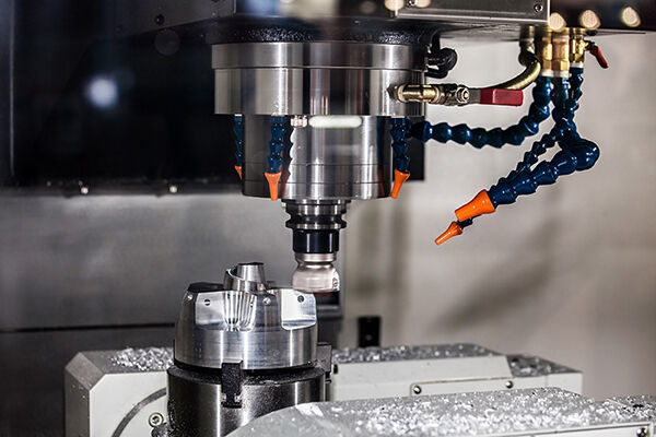
Face Milling Program with Complete Annotations
Face milling removes material from the top surface of a workpiece, creating a flat, smooth finish. This operation is foundational—you'll encounter it in countless cnc scenarios where parts require precise reference surfaces before additional machining.
Here's a complete face milling program with line-by-line explanations:
O1001 (FACE MILL PROGRAM)
Program number and description: Every program starts with an "O" followed by a unique number. The text in parentheses is a comment—machines ignore it, but operators rely on it for quick identification. Always name your programs descriptively.
G21 G17 G40 G49 G80 G90
Safety line: This critical initialization line clears modal states and establishes predictable behavior. Here's what each code accomplishes:
- G21: Sets millimeter units (use G20 for inches)
- G17: Selects X-Y plane for circular interpolation
- G40: Cancels any active cutter compensation
- G49: Cancels tool length compensation
- G80: Cancels any active canned cycle
- G90: Establishes absolute positioning mode
Why include codes that might already be inactive? Because you never know what state the previous program left the machine in. This "belt and suspenders" approach prevents crashes caused by lingering modal commands.
T01 M06 (50MM FACE MILL)
Tool call and change: T01 selects tool number one from the magazine. M06 executes the physical tool change. The comment identifies the tool—essential for operators verifying correct setup.
G54
Work coordinate system: G54 activates the first work offset, telling the machine where your part zero is located. Without this, coordinates reference machine home—not your workpiece.
S1200 M03
Spindle activation: S1200 sets spindle speed to 1200 RPM. M03 starts clockwise rotation. Notice the spindle starts before approaching the workpiece—never plunge into material with a stationary tool.
G43 H01 Z50.0
Tool length compensation: This line is crucial for safe operation. G43 activates tool length compensation, H01 references the offset value stored for tool one, and Z50.0 positions the tool 50mm above the part. Why use G43? Because different tools have different lengths. Without compensation, the machine assumes all tools are identical—leading to crashes or air cuts.
G00 X-30.0 Y0.0
Rapid positioning: G00 moves at maximum speed to the start position. The tool approaches from outside the workpiece (X-30.0 places it 30mm beyond the part edge) to ensure a clean entry.
M08
Coolant activation: Flood coolant turns on after positioning but before cutting begins. Activating coolant too early wastes fluid and creates mess; activating during the cut risks thermal shock to the tool.
G00 Z2.0
Approach height: Rapid descent to 2mm above the surface. This intermediate position allows the subsequent feed move to engage material smoothly.
G01 Z-2.0 F150
Plunge cut: G01 executes a controlled linear move at 150mm/min feedrate, cutting 2mm into the material. The slower feed prevents tool shock during initial engagement.
G01 X130.0 F800
Face milling pass: The tool travels across the workpiece at 800mm/min, removing material along the way. The higher feedrate is appropriate once the tool is fully engaged.
G00 Z50.0
Retract: Rapid withdrawal to safe height after completing the pass.
M09
Coolant off: Stops coolant flow before repositioning or ending the program.
G28 G91 Z0
Return to home: G28 sends the Z-axis to machine home. G91 makes this an incremental move (from current position), preventing unexpected travel paths.
M05
Spindle stop: Halts spindle rotation after retracting to safe position.
M30
Program end: Terminates execution and rewinds the program for the next cycle.
Pocket Milling Example for Rectangular Cavities
Pocket milling creates enclosed cavities—think of a smartphone case or a mounting bracket with recessed areas. This operation requires multiple step-down passes because removing too much material at once overloads the tool and generates excessive heat.
The following program mills a 60mm x 40mm rectangular pocket, 12mm deep, using 4mm step-downs:
O1002 (RECTANGULAR POCKET)
G21 G17 G40 G49 G80 G90
T02 M06 (16MM END MILL)
G54
S2000 M03
G43 H02 Z50.0
G00 X10.0 Y10.0
Start position: The tool positions at the pocket's corner. For cnc definitions of pocket starting points, programmers typically begin at the lower-left corner and work outward.
M08
G00 Z2.0
G01 Z-4.0 F100
First depth pass: The tool plunges to 4mm depth—one-third of the total pocket depth. Taking 4mm passes with a 16mm endmill follows the general rule: depth of cut shouldn't exceed one-quarter to one-half of tool diameter.
G01 X50.0 F600
G01 Y30.0
G01 X10.0
G01 Y10.0
Pocket perimeter: These four lines trace the rectangular boundary. The tool follows a clockwise path, which for this setup provides conventional milling (tool rotation opposes feed direction). Some programmers prefer climb milling for better surface finish—the direction choice depends on material and machine rigidity.
G00 Z2.0
G01 Z-8.0 F100
Second depth pass: Retract, reposition, and plunge to 8mm total depth.
G01 X50.0 F600
G01 Y30.0
G01 X10.0
G01 Y10.0
G00 Z2.0
G01 Z-12.0 F100
Final depth pass: The third pass reaches full 12mm depth, completing the pocket.
G01 X50.0 F600
G01 Y30.0
G01 X10.0
G01 Y10.0
G00 Z50.0
M09
G28 G91 Z0
M05
M30
Notice the repetitive structure? Real-world programmers often use subprograms or loops to avoid writing identical passes repeatedly. However, understanding the expanded version helps beginners grasp what's actually happening at each depth level.
These annotated cnc scenarios demonstrate how theoretical knowledge transforms into functional programs. When exploring cnc roleplay ideas for practice, start by modifying these examples—change dimensions, adjust feedrates, or add additional passes. Hands-on experimentation with simulation software builds confidence before running code on actual machines.
With milling fundamentals covered, turning operations introduce different programming conventions—where the X-axis represents diameter rather than linear position, and cylindrical geometry demands unique approaches.
CNC Turning and Lathe Programming Walkthrough
Transitioning from milling to turning requires a mental shift. The machine looks different, the workpiece rotates instead of the tool, and—most importantly—the coordinate system follows completely different conventions. Understanding these distinctions is essential before examining actual lathe programming examples.
What is cnc roleplay between milling and turning programming? In essence, while both use G-code fundamentals, turning flips several assumptions. The X-axis no longer represents horizontal travel—it defines diameter. The Z-axis runs parallel to the spindle, controlling longitudinal movement along the part. Getting these conventions wrong means programming a part twice the intended size or crashing into the chuck.
Key Differences Between Milling and Turning Programming
Before diving into code, you need to understand how lathe programming diverges from what you learned in milling:
- X-axis represents diameter: When you program X20.0 on a lathe, you're specifying a 20mm diameter—not a 20mm distance from center. Some machines operate in radius mode, but diameter mode is more common. Always verify which mode your machine uses.
- Z-axis is longitudinal: Z runs parallel to the spindle centerline. Negative Z moves toward the chuck; positive Z moves toward the tailstock. This orientation affects how you visualize toolpaths.
- No M06 for tool changes: Unlike mills, most lathes execute tool changes immediately when the T-word appears. The format often includes wear offset encoding (e.g., T0101 selects tool 1 with wear offset 1).
- Two-axis simplicity: Basic lathes use only X and Z. You can ignore Y entirely—leave it out of programs completely.
- G18 plane selection: Turning operations occur in the X-Z plane, so G18 is standard rather than G17 used in milling.
- Tool nose radius compensation: Lathes use G41/G42 differently, accounting for the insert's nose radius when profiling curved surfaces.
These differences mean you cannot simply copy milling logic into turning programs. The coordinate system and machine behavior demand a fresh approach.
External Turning Program for Cylindrical Parts
This complete program demonstrates facing, rough turning, and finish turning operations on a cylindrical workpiece. Each section builds logically from initialization through final retraction.
O2001 (EXTERNAL TURNING EXAMPLE)
Program identification: Clear naming helps operators identify the job quickly.
G18 G21 G40 G80 G99
Safety initialization: G18 selects the X-Z plane for turning. G21 sets millimeter units. G40 cancels tool nose compensation. G80 cancels canned cycles. G99 sets feed per revolution mode—critical for turning where consistent chip load matters regardless of diameter.
T0101
Tool selection: This calls tool 1 with wear offset 1. The lathe immediately indexes the turret—no M06 required. Using separate wear offsets for each feature allows fine-tuning tolerances independently.
G54
Work coordinate system: Establishes part zero, typically at the finished face on the spindle centerline.
G50 S2500
Maximum spindle speed: G50 limits RPM to 2500, preventing dangerous speeds when cutting small diameters with constant surface speed active.
G96 S200 M03
Constant surface speed: G96 maintains 200 meters per minute at the cutting point. As diameter decreases, RPM automatically increases—optimizing tool life and surface finish. M03 starts clockwise spindle rotation (from the operator's perspective, the chuck rotates toward you).
G00 X52.0 Z2.0
Rapid approach: Positions the tool outside the 50mm raw stock diameter, 2mm from the face. Always approach from a safe position.
M08
Coolant on: Activates before cutting begins.
G01 X-1.6 F0.15
Facing pass: Feeds across the face at 0.15mm per revolution. The X-1.6 value—slightly past center—ensures complete face cleanup. This negative X works because the tool passes through the centerline.
G00 Z1.0
G00 X50.0
Reposition for turning: Retracts in Z, then rapids to the starting diameter for rough turning.
G01 Z-45.0 F0.25
Rough turning pass: Feeds along Z at 0.25mm/rev, turning the 50mm diameter to 45mm length.
G00 X52.0
G00 Z1.0
G00 X48.0
G01 Z-45.0 F0.25
Second rough pass: Steps down 2mm in diameter and repeats. Multiple passes remove material progressively without overloading the tool.
G00 X50.0
G00 Z1.0
G42 X46.0
Finish pass with compensation: G42 activates tool nose radius compensation on the right side. This accounts for the insert's curved tip when following the programmed path, ensuring the finished diameter matches specifications exactly.
G01 Z0 F0.08
G01 Z-45.0
G01 X50.0
G40
Complete profile and cancel compensation: The slower 0.08mm/rev feed improves surface finish. G40 cancels compensation before retracting.
G00 X100.0 Z50.0
M09
M05
M30
Program end sequence: Retracts to safe position, stops coolant and spindle, ends program.
Threading Operation Code Walkthrough
Threading represents one of CNC turning's most sophisticated operations. The G76 canned cycle handles the complexity of multiple passes, depth management, and synchronization between spindle rotation and tool feed.
According to CNC Cookbook's threading guide, the G76 cycle dynamically adjusts cut depth on each pass to equalize material removal—compensating for the triangular thread form that engages more material as depth increases.
Here's a threading example for cutting a 20mm x 2.5 pitch external thread:
O2002 (THREADING EXAMPLE M20x2.5)
G18 G21 G40 G97 S800 M03
Note G97: Threading requires constant RPM mode (G97), not constant surface speed. Spindle synchronization fails with varying RPM.
T0303
Threading tool: A dedicated threading insert with 60-degree profile for metric threads.
G00 X22.0 Z5.0
Start position: Positions outside thread diameter with Z clearance for spindle synchronization.
G76 P010060 Q100 R0.05
First G76 line (parameters): This establishes threading behavior:
- P010060: Three two-digit values combined. "01" specifies one spring pass (cleans up thread). "00" sets chamfer amount. "60" indicates 60-degree tool angle.
- Q100: Minimum cutting depth of 0.1mm (value in microns) prevents excessively light passes.
- R0.05: Finish allowance of 0.05mm for the final pass.
G76 X17.0 Z-30.0 P1350 Q400 F2.5
Second G76 line (geometry):
- X17.0: Final thread root diameter (major diameter minus twice thread depth).
- Z-30.0: Thread end position—30mm thread length.
- P1350: Thread depth of 1.35mm (value in microns), calculated from thread pitch and form.
- Q400: First pass depth of 0.4mm—the deepest cut, as recommended for managing tool load.
- F2.5: Thread pitch of 2.5mm (the "lead" determining feed per spindle revolution).
The machine automatically calculates subsequent pass depths, gradually reducing them to maintain consistent cutting forces. For a 1.35mm total depth starting at 0.4mm, simulation tools estimate approximately 6-8 passes depending on the exact parameters.
G00 X50.0
G00 Z50.0
M05
M30
Understanding cnc role play between manual threading calculations and the G76 cycle's automation reveals why canned cycles exist. Programming each pass manually would require calculating progressively shallower depths following a specific formula—the cycle handles this complexity automatically.
These turning examples demonstrate the structured approach that makes CNC lathe programming predictable and repeatable. With external turning and threading fundamentals established, application-specific operations like drilling cycles and contour profiling build on these same principles across different machining contexts.
Application-Based CNC Programming Examples
How do you know which drilling cycle to use for a specific hole? When should you switch from simple point-to-point drilling to peck drilling? These questions plague beginners—and the answers depend entirely on understanding how to do cnc operations based on application requirements rather than memorizing code sequences.
This section organizes cnc examples by what you're actually trying to accomplish. Whether you're drilling holes, following complex profiles, or cutting smooth contours, the underlying programming logic follows consistent patterns that transfer across machine types and control systems.
Drilling Cycle Examples Using Canned Cycles
Canned cycles automate repetitive drilling motions that would otherwise require multiple lines of code. Instead of manually programming each approach, plunge, retract, and reposition, a single G-code handles the entire sequence. According to CNC drilling optimization experts, choosing the right cycle depends on hole depth, material characteristics, and chip evacuation needs.
Understanding cnc what does it mean in drilling context starts with recognizing three fundamental cycles:
G81 - Simple Drilling Cycle
Use G81 for shallow holes where chip clearance isn't problematic—typically holes less than three times the drill diameter (under 3×D). The tool feeds to depth in one motion, then retracts rapidly.
G81 X25.0 Y30.0 Z-15.0 R2.0 F120
This single line drills a 15mm deep hole at coordinates X25, Y30. The R2.0 establishes the retract plane—2mm above the surface where rapid motion transitions to feed rate. After reaching Z-15.0, the tool rapids back to R-plane height.
G83 - Peck Drilling for Deep Holes
Deep holes (greater than 5×D) demand G83 peck drilling. The tool advances incrementally, fully retracting after each peck to clear chips from the flutes. This prevents chip packing that causes tool breakage and poor hole quality.
G83 X25.0 Y30.0 Z-60.0 R2.0 Q5.0 F80
The Q5.0 parameter specifies 5mm pecks. The machine drills 5mm, retracts completely to R-plane, rapids back to just above the previous depth, then pecks another 5mm. This continues until reaching Z-60.0—twelve cycles for a 60mm hole.
For sticky materials like stainless steel where chips don't break cleanly, full retraction is essential to flush chips and prevent welding to the drill.
G73 - High-Speed Chip Breaking Cycle
G73 offers a middle ground—the tool pecks without full retraction. After each increment, it retracts only slightly (typically 1-2mm) to break chips, then immediately feeds to the next depth. This significantly reduces cycle time compared to G83 while still managing chip formation.
G73 X25.0 Y30.0 Z-40.0 R2.0 Q8.0 F150
Ideal for aluminum and other materials that produce short, manageable chips, G73 can cut drilling time by 40% or more compared to full-retract peck drilling. However, it's unsuitable for materials prone to chip welding or deep holes requiring coolant flushing.
Drilling Cycle Comparison
The following table summarizes when to apply each cycle based on application requirements:
| Cycle | Motion Pattern | Key Parameters | Best Applications | Limitations |
|---|---|---|---|---|
| G81 | Single plunge, rapid retract | R-plane, Z-depth, F-feed | Shallow holes under 3×D, soft materials, spot drilling | No chip clearing—fails in deep holes |
| G83 | Peck with full retraction to R-plane | R-plane, Z-depth, Q-peck, F-feed | Deep holes over 5×D, stainless steel, titanium, sticky materials | Slowest cycle—significant non-cutting time |
| G73 | Peck with partial retract (chip break only) | R-plane, Z-depth, Q-peck, F-feed | Medium-depth holes in aluminum, brass, short-chip materials | Poor chip evacuation for deep holes or gummy materials |
Notice how each coordinate in a drilling program executes one complete cycle. Programming multiple holes becomes straightforward:
G83 X25.0 Y30.0 Z-60.0 R2.0 Q5.0 F80
X50.0 Y30.0
X75.0 Y30.0
X100.0 Y30.0
G80
Each subsequent line inherits the active cycle parameters—only the coordinates change. G80 cancels the drilling cycle when hole-making operations are complete.
Profile Milling and Contour Programming Techniques
While drilling uses canned cycles, profiling requires manually sequencing motion commands to follow complex shapes. Understanding what is cnc stand for in contour programming means mastering how G01, G02, and G03 combine to trace 2D geometries.
Consider machining a part profile that includes straight edges, rounded corners, and arc transitions. Each segment demands the appropriate interpolation command:
G00 X-5.0 Y0 (Approach position)
G01 X0 Y0 F300 (Lead-in move)
G01 X80.0 (Straight edge)
G02 X90.0 Y10.0 R10.0 (Clockwise arc - rounded corner)
G01 Y50.0 (Straight edge upward)
G03 X80.0 Y60.0 R10.0 (Counter-clockwise arc)
G01 X20.0 (Straight edge)
G03 X10.0 Y50.0 R10.0 (Another CCW arc)
G01 Y10.0 (Straight edge downward)
G02 X20.0 Y0 R10.0 (Final corner arc)
G01 X0 (Return to start)
This sequence traces a rounded rectangle with 10mm corner radii. Notice the pattern:
- G01 handles all straight segments—horizontal, vertical, or angled
- G02 cuts clockwise arcs (tool moves right while curving toward center)
- G03 cuts counter-clockwise arcs (tool moves left while curving)
- R-values define arc radius when center-point programming (I, J, K) isn't required
The distinction between cnc means what in manual versus CAM-generated contours becomes apparent when examining complex shapes. Manual programming works for simple geometries but becomes impractical for organic curves or 3D surfaces.
CAM Software vs. Manual Programming
When do you write code by hand, and when should CAM software generate it? The answer depends on part complexity, production volume, and programming time constraints.
According to CAM integration specialists, a complex part requiring two weeks of manual programming was completed in just two hours using CAM software—with the added benefit of simulation verification before machine time.
Here's where each approach excels:
Manual Programming Advantages
- Simple drilling patterns and face milling operations
- Quick modifications to existing programs
- Situations where CAM software isn't available
- Educational purposes—understanding code fundamentals
CAM Software Advantages
- Complex 3D surfaces and multi-axis operations
- Automatic toolpath optimization for cycle time
- Collision detection through simulation before cutting
- Revision changes update automatically from CAD modifications
- Consistent output quality regardless of programmer experience
The cnc rp (rapid prototyping) environment particularly benefits from CAM automation. When design iterations happen daily, manually reprogramming each revision wastes valuable time. CAM software regenerates toolpaths from updated models in minutes rather than hours.
Consider the workforce implications too. Experienced G-code programmers are increasingly rare—finding skilled manual programmers is described as finding a needle in a haystack. CAM software allows less experienced operators to generate production-ready code, democratizing CNC programming capabilities across manufacturing teams.
However, understanding manual programming remains valuable even when using CAM. You'll need to verify post-processor output, troubleshoot unexpected machine behavior, and make on-the-fly adjustments at the control. The cnc rp workflow benefits most when programmers understand both the software interface and the underlying code it generates.
These application-based examples demonstrate how drilling, profiling, and contouring operations share fundamental programming logic while requiring different strategic approaches. The next consideration is how these techniques adapt across industries—where automotive volume production demands different priorities than aerospace precision or medical device traceability.

Industry Applications from Automotive to Aerospace
You've mastered G-code fundamentals and explored application-based programming examples. But here's the reality check: the same CNC program that works perfectly for a general manufacturing shop might fail completely in aerospace or medical device production. Why? Because each industry imposes unique requirements that fundamentally shape how parts are programmed, machined, and verified.
Understanding the meaning cnc takes on within different sectors reveals why identical tolerances, materials, and documentation standards don't apply universally. The c.n.c meaning shifts based on context—automotive prioritizes repeatability at scale, aerospace demands material traceability, and medical requires biocompatibility certifications that general manufacturing never encounters.
Automotive Component Machining Requirements
Automotive manufacturing operates on a fundamental principle: produce thousands—sometimes millions—of identical parts with consistent quality and minimal variation. When you're machining engine blocks, transmission housings, or chassis components, even slight deviations across a production run create assembly problems downstream.
What is cnc mean in automotive context? It means Statistical Process Control (SPC) monitoring every critical dimension in real-time. According to HLH Rapid's tolerance guide, standard CNC tolerances typically fall around ±0.005" (0.13mm), but high-performance automotive components often demand ±0.001" (0.025mm) or tighter—especially for engine components where thermal expansion and high-RPM operation require precise fits.
Consider the production demands automotive suppliers face:
- Volume production consistency: Running 10,000+ parts requires programs that produce identical results from the first piece to the last. Tool wear compensation, automatic offset adjustments, and predictive maintenance become essential rather than optional.
- Just-in-time delivery: Automotive supply chains operate with minimal inventory buffers. Late deliveries halt assembly lines—costing manufacturers thousands per minute of downtime.
- IATF 16949 certification: This automotive-specific quality standard requires documented evidence of process control, measurement system analysis, and continuous improvement. Shops without certification typically cannot supply major automakers.
- Cost optimization at scale: Cycle time reductions measured in seconds translate to significant savings when multiplied across high-volume runs. Program optimization focuses heavily on minimizing non-cutting time.
For manufacturers requiring this level of automotive-grade precision, IATF 16949-certified facilities like Shaoyi Metal Technology deliver high-tolerance components with the Statistical Process Control systems that automotive supply chains demand. Their capabilities scale from rapid prototyping to mass production—addressing the full product development cycle that automotive projects require.
Aerospace and Medical Precision Standards
While automotive emphasizes repeatability and speed, aerospace manufacturing operates under entirely different priorities. What is cnc slang in a machine shop might reference quick-and-dirty approaches—but aerospace tolerates none of that mentality. Every cut, every measurement, and every material lot demands complete documentation.
According to Modus Advanced's precision manufacturing analysis, tight tolerance CNC machining services achieve dimensional control at ±0.0025mm (±0.0001") or better, with industry leaders reaching tolerances of 1-3 microns for critical aerospace applications. This level of precision requires temperature-controlled environments maintaining 20°C ± 1°C (68°F ± 2°F) throughout production.
Aerospace-Specific Requirements
- Exotic material machining: Titanium alloys, Inconel, and carbon fiber composites demand specialized tooling and conservative cutting parameters. Titanium's low thermal conductivity concentrates heat at the cutting interface, requiring careful speed and feed management to prevent dimensional instability.
- Complex geometries: Turbine blades, structural brackets, and control surface components feature contoured surfaces that push 5-axis machining capabilities to their limits.
- Complete traceability: AS9100D certification requires documentation linking every part to specific material lots, machine settings, tool batches, and operator qualifications. A single undocumented deviation can ground an entire fleet.
- Material integrity verification: Non-destructive testing, surface inspection, and material certification documentation accompany every critical component through the supply chain.
Medical Device Manufacturing Standards
Medical device production represents perhaps the most demanding CNC application—where dimensional accuracy directly impacts patient safety. As CNCRUSH's medical industry analysis explains, implantable devices require biocompatible surface finishes and dimensional precision measured in microns.
- Biocompatible materials: Surgical-grade stainless steel, titanium, and PEEK plastics must maintain material properties through machining and subsequent sterilization cycles.
- Surface finish requirements: Implants contacting tissue or bone require specific Ra values—often below 0.8 micrometers—achieved through careful finishing operations and sometimes secondary polishing.
- FDA compliance documentation: Device History Records (DHR) document every manufacturing step. Missing or incomplete documentation prevents market release regardless of part quality.
- Validation protocols: Installation Qualification (IQ), Operational Qualification (OQ), and Performance Qualification (PQ) validate that equipment and processes consistently produce conforming parts.
The tolerance requirements speak for themselves. According to precision manufacturing specialists, surgical instruments and implantable devices routinely require tolerances of ±0.0025mm (±0.0001")—roughly 40 times tighter than standard machining operations.
Industry Priority Comparison
What matters most varies dramatically by sector. The following comparison illustrates how identical CNC capabilities serve fundamentally different priorities:
| Priority Factor | Automotive | Aerospace | Medical Device |
|---|---|---|---|
| Primary Focus | Repeatability at volume | Material integrity | Biocompatibility |
| Typical Tolerance | ±0.025mm to ±0.05mm | ±0.0025mm to ±0.01mm | ±0.0025mm to ±0.01mm |
| Key Certification | IATF 16949 | AS9100D | ISO 13485, FDA registration |
| Documentation Level | SPC charts, capability studies | Full traceability, NDT reports | Device History Records |
| Production Volume | 10,000+ typical runs | Low-volume, high-mix | Varies by device class |
| Cost Driver | Cycle time reduction | First-pass yield | Validation compliance |
Notice how different industries define success differently. Automotive shops celebrate shaving seconds from cycle times across million-unit production runs. Aerospace manufacturers invest heavily in simulation and verification to ensure first-part success—because scrapping a $50,000 titanium forging destroys profitability. Medical device producers build extensive validation documentation that sometimes exceeds the machining time itself.
Understanding what is cnc in dating terms has nothing to do with manufacturing—it's unrelated internet slang. Similarly, cnc meaning relationship refers to entirely different contexts outside precision machining. In manufacturing, CNC relationships involve supplier qualifications, process validations, and quality agreements that determine whether a shop can serve specific industries.
These industry-specific requirements explain why experienced programmers tailor their approaches based on the end application. The same milling operation might use different tooling, speeds, and verification methods depending on whether the part ends up in a transmission, a jet engine, or an implantable device. As you develop your programming skills, recognizing these contextual differences separates competent technicians from true manufacturing professionals.
Of course, even the best-planned programs sometimes encounter problems. Understanding how to identify and resolve common CNC programming errors prevents costly crashes and scrapped parts—skills that become increasingly valuable as you work with tighter tolerances and more demanding applications.

Troubleshooting Common CNC Programming Errors
Even experienced programmers make mistakes. The difference between a minor inconvenience and a catastrophic crash often comes down to catching errors before the spindle starts turning. Whether you're searching for cnc slang meaning in machining forums or studying formal programming guides, you'll find that troubleshooting skills separate confident operators from anxious beginners.
Understanding what does cnc mean slang-wise in shop floor conversations often involves references to crashed tools, scrapped parts, or near-miss incidents. These stories underscore why systematic error prevention matters. According to FirstMold's CNC programming guide, program verification and test cutting are essential steps before committing to production—skipping them invites costly mistakes.
Syntax Errors and How to Identify Them
Syntax errors represent the most common—and often the easiest to fix—programming mistakes. The machine controller rejects obviously malformed code, but subtle errors can slip through and cause unexpected behavior during execution.
Here's what typically goes wrong and how to fix it:
| Error Type | Symptoms | Common Cause | Solution |
|---|---|---|---|
| Missing decimal points | Tool moves to unexpected position; alarm on some controllers | Typing X10 instead of X10.0 or X1.0 | Always include decimal points—X10.0 is unambiguous |
| Incorrect G-code sequence | Machine behaves erratically; tool doesn't follow expected path | Modal codes conflict or weren't cancelled properly | Review safety line; ensure G40, G49, G80 cancel previous states |
| Wrong coordinate system | Part machined in wrong location; tool crashes into fixture | Using G54 when G55 was intended; forgetting work offset entirely | Verify work offset matches setup sheet; check G54-G59 selection |
| Improper tool compensation | Oversized or undersized features; gouging on profiles | Wrong H-offset number; G41/G42 applied incorrectly | Match H-number to tool number; verify compensation direction |
| Feed rate errors | Tool breakage; poor surface finish; excessive cycle time | Missing F-word; unrealistic feed value; wrong units | Confirm F-value is appropriate for material and operation |
| Spindle speed omission | Machine attempts cut with stationary spindle; alarm | S-word missing or placed after M03 | Program S-value before M03; verify RPM is reasonable |
The cnc meaning slang interpretation often heard in shops—"Check Numerical Carefully"—reflects hard-won lessons about decimal placement. Programming X25 instead of X2.5 moves the tool ten times farther than intended. On some controllers, missing decimals default to the smallest increment; on others, they're interpreted as whole units. Either way, the result rarely matches your intent.
Toolpath Collision Prevention Strategies
Collisions represent the most expensive programming errors. A crashed spindle or destroyed fixture can cost thousands in repairs and weeks of downtime. As Hwacheon's troubleshooting guide emphasizes, improperly clamped parts or incorrect tool setups create dangerous conditions that proper verification prevents.
Experienced programmers rely on multiple verification layers before executing new programs:
- Dry runs without workpiece: Execute the program with no material in the machine. Watch tool movements to verify paths make sense relative to expected part geometry.
- Single-block execution: Step through the program one line at a time using the controller's single-block mode. This reveals unexpected rapid moves or questionable approach angles before they become collisions.
- Simulation software: According to CNC programming experts, modern CAM software can visualize the tool-cutting process before any metal is removed. Simulation detects interference between tools, holders, fixtures, and workpieces that static code review misses.
- Feedrate override at startup: Run new programs at 25-50% feedrate override initially. This provides reaction time to hit the emergency stop if something looks wrong.
If you've ever searched "cnc urban dictionary" looking for machining definitions, you've likely encountered colorful descriptions of collision aftermath. The manufacturing reality is less amusing—crashes damage expensive equipment, delay production schedules, and sometimes injure operators. Prevention through systematic verification is always cheaper than repair.
Pre-Run Verification Checklist
Before pressing cycle start on any program—especially new or modified code—experienced programmers complete verification steps that prevent the most common failure modes:
- Work holding verification: Confirm the part is securely clamped and cannot shift during cutting. As machine tool specialists warn, improperly clamped parts lead to accidents, damage, and operator injury.
- Tool length measurement: Touch off each tool and verify offset values match the tool table. A 10mm error in tool length compensation drives the tool 10mm deeper than intended—potentially through the part and into the fixture.
- Work coordinate verification: Confirm the programmed work offset (G54, G55, etc.) matches the actual part location. Touch the spindle nose to a known reference point and compare displayed coordinates to expected values.
- Program number confirmation: Verify you're running the correct program for the current setup. Shops with multiple similar parts have run wrong programs against right setups—with predictable results.
- Tool inventory check: Confirm every tool called by the program is loaded in the correct magazine position with appropriate offset data entered.
- Coolant and chip management: Verify coolant levels are adequate and chip conveyors are functioning. Mid-cycle coolant failure causes thermal damage; chip buildup interferes with tool changes.
- First-piece inspection plan: Know which dimensions you'll measure on the first part and have appropriate gauging ready. Don't run a second part until the first passes inspection.
This systematic approach transforms programming from anxious guesswork into confident execution. Every experienced machinist has stories of crashes avoided through careful verification—and probably a few they wish they'd caught in time. Building verification habits early prevents joining the latter category.
With troubleshooting fundamentals established, the natural question becomes: how do you progress from catching errors in existing programs to confidently writing original code? The learning pathway from beginner to competent CNC programmer follows predictable stages that build skills systematically.
Advancing Your CNC Programming Skills
You've studied the cnc examples throughout this article—from basic G-code commands to industry-specific applications. But here's the question that matters now: what's cnc programming proficiency actually look like in practice, and how do you get there?
The gap between understanding code and confidently writing production-ready programs doesn't close overnight. According to JLC CNC's programming guide, CNC programming is a highly practical skill where theoretical knowledge only becomes valuable through constant practice. The journey from curious beginner to competent programmer follows a predictable progression—one that rewards systematic skill-building over random exploration.
Building Your CNC Programming Skill Progression
Whats cnc stand for in terms of learning investment? It means committing to structured development rather than hoping skills materialize through osmosis. The most efficient path moves through distinct phases, each building on the previous foundation:
- Master G-code fundamentals: Before touching simulation software or CAM systems, internalize the core commands covered earlier in this article. Understand what G00 versus G01 means intuitively. Know why G90 and G91 produce different results. Recognize M-code sequences without consulting references. This foundational fluency makes everything else possible.
- Practice with simulation software: According to CNC programming experts, simulation tools like GibbsCAM and Vericut let you verify program correctness and optimize toolpaths without consuming material. Start running the cnc examples from this article through simulation—watch how code translates to tool movement. Experiment with parameter changes and observe the results risk-free.
- Modify existing programs: Take working programs and make small changes. Adjust feedrates. Modify pocket dimensions. Change drilling depths. Each modification teaches cause-and-effect relationships between code and outcomes. You'll learn faster from intentional experimentation than passive observation.
- Write simple programs from scratch: Start with basic operations—face milling a rectangular block, drilling a hole pattern, turning a simple diameter. Don't attempt complex contours initially. Success with fundamentals builds confidence for advanced challenges.
- Learn CAM software basics: Modern manufacturing increasingly relies on CAM-generated toolpaths. Mastercam's workflow documentation describes the process: import a 3D CAD model, define machining operations, and let the software generate optimized toolpaths. Understanding CAM doesn't replace G-code knowledge—it amplifies what you can accomplish with it.
- Understand post-processor customization: Post processors translate CAM toolpaths into machine-specific G-code. As Mastercam explains, each machine's kinematics dictate how the post processor should format output code. Learning to configure and troubleshoot post processors connects CAM software to physical machine capabilities.
This progression isn't arbitrary. Each phase develops skills that the next phase requires. Skipping steps—jumping straight to CAM software without understanding the code it generates—creates knowledge gaps that eventually cause problems.
From Manual Code to CAM Integration
Where does what does mean cnc become truly practical? When you can move fluidly between manual programming and CAM-assisted workflows based on what each job demands.
Consider this realistic scenario: your CAM software generates a complex toolpath, but the post-processed code includes unnecessary rapid moves that add cycle time. Without G-code fluency, you're stuck with inefficient output. With manual programming skills, you identify the waste, modify the code directly, and optimize the operation—saving minutes per part that compound across production runs.
The learning resources available today make skill development more accessible than ever:
- Free structured training: According to DeFusco's course analysis, platforms like Titans of CNC Academy offer free project-based lessons with downloadable models and completion certificates—practical training you can start tonight.
- Vendor-specific paths: If your shop runs Mastercam, Mastercam University provides training aligned to the actual software interface you'll use daily. The buttons, terminology, and strategies you practice match real production workflows.
- Machine builder programs: The Haas Certification Program focuses on operator-to-machinist fundamentals—ideal for building confidence before advancing to complex programming.
- Manufacturer documentation: Controller manuals from Fanuc, Siemens, and other manufacturers provide definitive references for machine-specific commands and capabilities.
- Industry certifications: NIMS (National Institute for Metalworking Skills) certification validates programming competency in ways employers recognize and value.
Hands-on machine time remains irreplaceable regardless of how much simulation practice you complete. The feedback loop between writing code, running it on actual equipment, and measuring results accelerates learning in ways that screens alone cannot replicate.
Turning Learning Into Production
At some point, cnc mean shifts from academic understanding to practical output. You're no longer just learning—you're producing parts that meet specifications and satisfy customers.
When you're ready to see your programming skills translate into physical components, manufacturers like Shaoyi Metal Technology offer rapid prototyping with lead times as fast as one working day. This capability lets programmers validate their code against real-world results quickly—turning digital designs into complex chassis assemblies or custom metal bushings that demonstrate what skilled CNC programming enables.
The transition from learning to production doesn't require perfection. It requires systematic skill development, access to verification tools, and willingness to learn from mistakes. Every experienced programmer started exactly where you are now—studying examples, experimenting with code, and gradually building confidence through practice.
The cnc examples throughout this article provide your starting foundation. The progression steps outlined above give you a roadmap. The resources mentioned offer structured support. What remains is your commitment to deliberate practice—the ingredient that transforms understanding into capability.
Frequently Asked Questions About CNC Examples
1. What is an example of a CNC scenario in manufacturing?
Common CNC manufacturing scenarios include face milling operations that create flat reference surfaces, pocket milling for rectangular cavities, external turning for cylindrical parts, and threading operations using G76 canned cycles. Each scenario requires specific G-code sequences—for instance, face milling combines G00 rapid positioning, G01 linear interpolation at controlled feedrates, and proper tool length compensation with G43. IATF 16949-certified manufacturers like Shaoyi Metal Technology handle complex CNC scenarios ranging from rapid prototypes to mass-produced automotive components with tight tolerances.
2. What are some examples of different types of CNC machines?
CNC machines span multiple categories based on their operations. CNC milling machines handle face milling, pocket milling, and profile cutting using rotating tools. CNC lathes perform turning, facing, and threading operations on cylindrical workpieces. Other types include CNC routers for softer materials, plasma cutters for sheet metal, laser cutting machines for precision profiles, EDM machines for intricate details, waterjet cutters for heat-sensitive materials, and grinding machines for ultra-precise surface finishes. Each machine type uses similar G-code fundamentals but with application-specific programming conventions.
3. What is CNC short for and what does it mean?
CNC stands for Computer Numerical Control, referring to the computerized operation of machining tools that execute pre-programmed commands. The technology transforms digital CAD designs into precision-machined physical parts through automated control systems. CNC machines interpret G-code commands for geometric movements and M-code for operational functions like spindle activation and coolant control. This automation enables consistent repeatability, tight tolerances down to ±0.0025mm in precision applications, and complex geometries impossible with manual machining.
4. How do I choose between G81, G83, and G73 drilling cycles?
Selection depends on hole depth and material characteristics. Use G81 simple drilling for shallow holes under 3 times drill diameter where chip clearance isn't problematic. Choose G83 peck drilling with full retraction for deep holes exceeding 5 times diameter, especially in stainless steel or titanium where chips don't break cleanly. G73 chip-breaking cycle works best for medium-depth holes in aluminum and materials producing short chips—it pecks without full retraction, reducing cycle time by up to 40% compared to G83 while still managing chip formation effectively.
5. What's the difference between manual CNC programming and CAM software?
Manual programming involves writing G-code directly, ideal for simple operations like drilling patterns, face milling, and quick program modifications. CAM software generates toolpaths automatically from 3D CAD models, excelling at complex surfaces, multi-axis operations, and collision detection through simulation. According to industry specialists, parts requiring two weeks of manual programming can be completed in two hours using CAM. However, understanding manual programming remains essential for verifying CAM output, troubleshooting issues, and making on-the-fly adjustments at the machine control.