 Small batches, high standards. Our rapid prototyping service makes validation faster and easier —

Solving Cracking in Drawing Dies: Key Causes & Fixes

TL;DR
Cracking in drawing dies is a critical manufacturing failure primarily driven by excessive stress, material flaws, operational errors, and poor tool design. The main causes include localized compressive stress that leads to strain hardening, the release of internal stresses within the material, and metallurgical defects in either the die or the workpiece. Insufficient lubrication, improper equipment alignment, and flawed die geometry—such as incorrect radii or clearances—are also significant contributors to premature die failure.
Understanding the Critical Difference: Cracking vs. Splitting
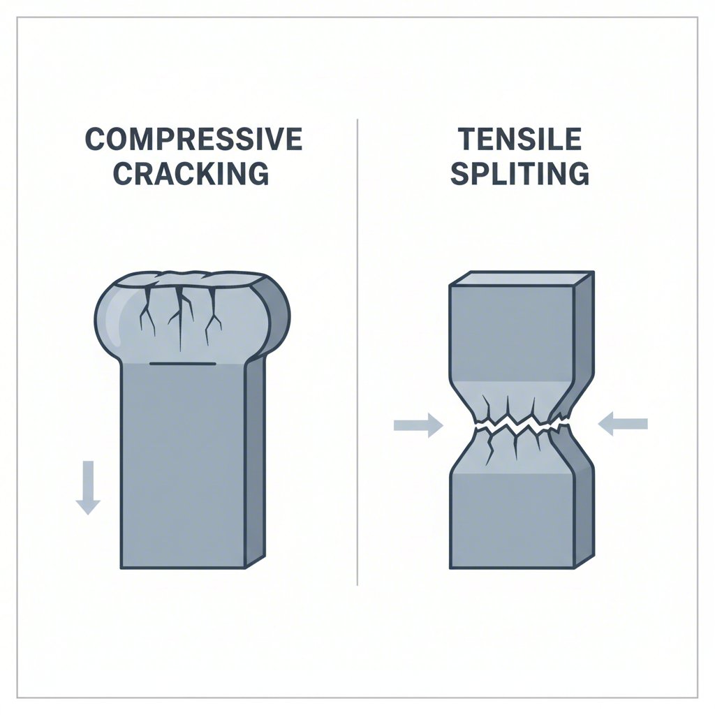
Before diagnosing a failure, it's essential to distinguish between cracking and splitting, as their root causes and solutions are fundamentally different. Misidentifying the failure mode often leads to incorrect and ineffective corrective actions. While both result in a rejected part, they originate from opposing stress states.
Splitting is a tensile failure. It occurs when the metal is overstretched beyond its maximum elongation capacity. This process is often preceded by a visible thinning of the material known as “necking.” Think of it like pulling a piece of taffy until it thins in the middle and eventually tears apart. In a drawing process, splitting typically appears as a horizontal rupture near a punch radius, where the material has been stretched too thin. Common solutions involve increasing the punch radius, improving lubrication, or using a material with better elongation properties.
Cracking, conversely, is a compressive failure. It results from too much localized compression, which causes the material to become overly work-hardened and brittle in a specific area. As detailed in an analysis by The Fabricator, this failure mode results in the metal at the break being thicker than its original state. Cracks often appear as vertical failures and are increasingly common with high-strength steels and stainless steels. Attempting to fix a crack with a solution meant for a split will only worsen the problem.
To aid in proper diagnosis, consider these key differences:
| Characteristic | Cracking (Compressive Failure) | Splitting (Tensile Failure) |
|---|---|---|
| Appearance | Typically a vertical open failure | Typically a horizontal rupture, often preceded by necking |
| Material Thickness at Break | Thicker than original material | Thinner than original material (thin-out) |
| Primary Cause | Excessive localized compression and strain hardening | Excessive localized stretching (tension) |
| Common Location | Areas of high compression, such as flanges or tight radii | Near punch radii or areas of high stretch |
Material-Related Causes and Inherent Defects
The physical and chemical properties of both the workpiece and the die itself are frequent sources of cracking. Failures originating from the material can be subtle but have significant consequences on production yield and tool life. These issues can be broadly categorized into problems with the raw material being drawn and defects within the die's construction material.
For the workpiece, poor raw material selection is a primary culprit. Materials with low plasticity or a high cold-hardening index, such as austenitic stainless steel, are particularly susceptible. During deformation, these materials can undergo a phase transformation that induces a brittle martensite structure, making them prone to cracking as explained by experts at Kanou Mould. Furthermore, surface imperfections on the blank, such as nicks or galling, can disrupt the smooth flow of material into the die, leading to fractures, a common issue highlighted by Accurate Forming.
On the tooling side, the quality of the die material is paramount. A die made from poor-quality carbide, for instance, can lead to catastrophic failure. An in-depth failure analysis in The Fabricator's Tube & Pipe Journal points to metallurgical defects like porosity from improper sintering as a major cause. When carbide powder is not properly sintered, the tungsten and cobalt components fail to mesh correctly, reducing the die's structural integrity and ability to withstand drawing stresses. This creates weak spots where cracks can easily initiate and propagate.
To mitigate these material-related failures, several strategies are effective:
- Material Selection: Choose materials with good plasticity and formability for the intended application. For materials that work-harden significantly, plan for an intermediate annealing process to restore ductility.
- Quality Control: Implement rigorous inspection of incoming raw materials to check for surface defects or inconsistencies in thickness.
- Die Material Specification: Insist on high-quality, properly sintered carbide or other appropriate tool steels from reputable suppliers. Ensure the die material is suited for the stresses of drawing specific workpiece materials.
Operational Failures: Process Stresses, Lubrication, and Alignment
Even with perfect materials and die design, errors in the drawing process itself are a major source of cracking. These operational failures often stem from the complex interplay of stress, friction, and mechanical setup. Addressing them requires careful monitoring and control of the manufacturing environment.
One of the most fundamental causes is the release of internal stress. As noted by multiple industry sources, internal stress is an inevitable byproduct of metal manufacturing. During the drawing process, these stored stresses are released, which can manifest as cracks, sometimes immediately after forming or even after a period of storage. This is particularly true for materials with a high hardening index.
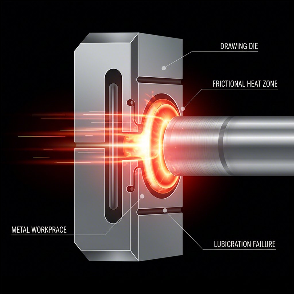
Insufficient lubrication is another critical operational failure. Lubricants form a protective film between the die and the workpiece, reducing friction and heat. When this film breaks down, metal-to-metal contact occurs, leading to galling, increased drawing forces, and ultimately, fractures. The choice of lubricant is vital; for challenging materials like stainless steel, specialized lubricants such as PVDF films may be necessary to maintain an effective barrier.
Finally, mechanical misalignment can introduce uneven stresses that cause premature die failure. A worn pulley feeding wire into a die at an incorrect angle, for example, creates an inconsistent wear pattern. This concentrates stress on specific points within the die, leading to localized wear and cracking. As one case study showed, the problem wasn't the die but the grooved pulley upstream that caused the misalignment.
Operators can use the following checklist to diagnose and prevent operational failures:
- Lubrication Check: Verify that the lubrication system is functioning correctly and that the appropriate lubricant for the material and process is being used.
- Alignment Verification: Regularly inspect all components of the draw bench, including pulleys and guides, for wear and ensure proper alignment of the workpiece into the die.
- Parameter Control: Ensure drawing speeds and reduction ratios are within the recommended limits for the material being processed.
- Stress Management: For materials prone to delayed cracking, consider stress-relieving heat treatments as soon as possible after forming.
Flawed Die Design and Substandard Construction
The design and construction quality of the drawing die are foundational to its performance and longevity. Flaws in either area can create stress concentrations and material flow issues that directly lead to cracking, regardless of material quality or operational precision. A well-designed die facilitates smooth material flow, while a poorly designed one fights against it.
Common design flaws include improper geometry. For instance, if the punch and die radii are too small (too sharp), they can restrict material from flowing into the die cavity, increasing tensile stress and causing fractures. Conversely, if the radius is too large, it can lead to wrinkling. According to CNstamping, improper clearance between the punch and die is another frequent cause of cracking. Likewise, an insufficient approach angle length concentrates drawing pressure into too small an area, squeezing out lubricant and leading to galling and failure.
Substandard construction can undermine even a perfect design. The fit between the carbide insert and the steel case is critical for both mechanical support and heat dissipation. If the insert is not fully supported—for example, due to a tapered case ID—it cannot withstand the drawing forces and will crack. Proper heat-shrinking of the insert into the case is essential to ensure maximum contact area, which allows the case to act as a heat sink and prevent the insert from overheating.
To avoid these issues, partnering with a knowledgeable and experienced die manufacturer is crucial. A specialist can ensure the tool is designed and built correctly for the specific application, taking into account the material properties, draft, and operational stresses. For instance, specialists like Shaoyi (Ningbo) Metal Technology Co., Ltd. utilize advanced CAE simulations to optimize die design and leverage deep project management expertise to deliver high-quality, reliable tooling for demanding applications like automotive stamping.
Key considerations for die design and construction include:
- Optimized Geometry: Ensure radii, clearances, and approach angles are tailored to the specific material and part geometry.
- Proper Insert Support: Use centerless-ground inserts and ensure they are fully supported within the case to maximize heat transfer and mechanical strength.
- Material Flow: For out-of-square stock, consider designs with recessed conical corners to prevent sharp corners from digging into the die flats.
- Expert Collaboration: Work closely with tooling suppliers to validate designs and ensure high-quality construction practices are followed.
Frequently Asked Questions
1. What is the reason for the die block to crack during the forming process?
A die block can crack for several reasons, primarily related to stress and material integrity. The main causes include stress concentration from flawed die design or misalignment, which focuses immense force on a small area. Another key factor is the uneven distribution of carbides in the tool steel, creating weak points. Finally, high temperatures during operation can reduce the material's resistance to cracking, especially if the die is not properly cooled.
2. What causes cracking in metal?
Cracking in metal is generally caused by stress exceeding the material's strength. This can happen in various ways, including mechanical overload from applied forces (like in a drawing process), thermal stress from rapid heating or cooling, residual internal stress from previous manufacturing steps, and environmental factors like corrosion that weaken the material over time. Material defects like porosity or inclusions also act as starting points for cracks.
3. What causes most cracks in sheet metal forming?
In sheet metal forming, most cracks are caused by excessive localized deformation. This is often due to improper die clearance, where the gap between the punch and die is too small, forcing the metal to shear or crack. Poor alignment can also create uneven stress, leading to failure. Another common cause is inadequate material support or clamping, which allows the sheet metal to stretch unevenly and exceed its elongation limit, resulting in splits or cracks.