 Small batches, high standards. Our rapid prototyping service makes validation faster and easier —

Solving Part Failure: A Forged Component Failure Analysis Case Study
TL;DR
Case studies solving part failure with forged components rely on rigorous technical investigation to uncover root causes. Through detailed metallurgical analysis, mechanical testing, and advanced simulation, engineers can identify issues like material defects, process errors, or design flaws. The resolution often involves optimizing heat treatment protocols, adjusting material chemistry, or refining the forging process itself to enhance component durability and prevent future failures.
The Problem: A Framework for Understanding Part Failure in Forging
In the high-stakes world of industrial manufacturing, the failure of a forged component can lead to costly downtime, safety risks, and significant financial loss. Understanding the nature of these failures is the first step toward resolution. Failures in forged parts are broadly categorized by the types of defects that precipitate them. These defects can be macroscopic, like visible cracks or deformations, or microscopic, hidden deep within the material's grain structure. The premature failure of forging dies, for instance, costs the industry millions annually by producing flawed parts and halting production.
Common defects observed in forged components can be classified into several key groups. Surface defects are often the most apparent and include issues such as laps or folds, where material overlaps but does not fuse, creating a weak point. Cracks and bubbles, often resulting from trapped gases or improper material flow, are also frequent culprits. A case involving forged aluminum components highlighted how such defects can compromise the integrity of a part. Another significant issue is underfill, where the forging material does not completely fill the die cavity, resulting in an incomplete or dimensionally inaccurate part.
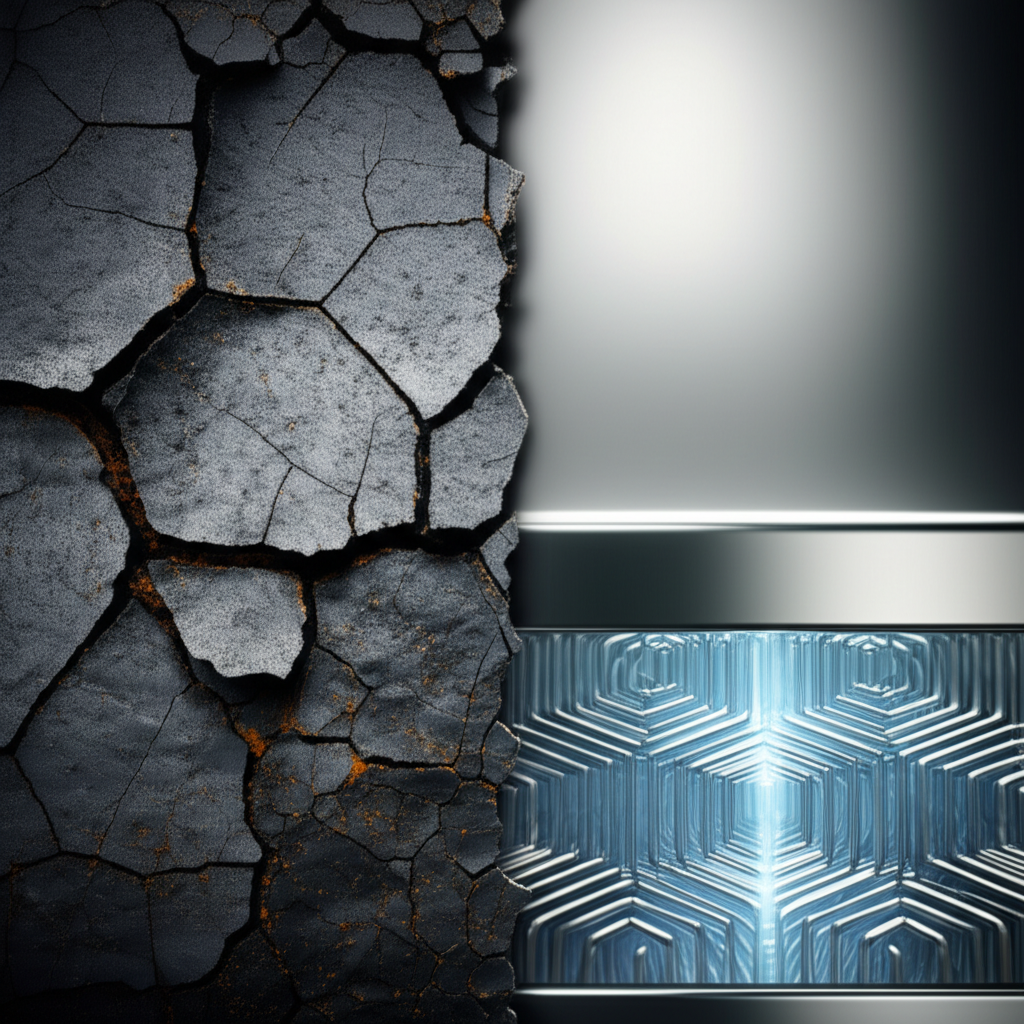
Beyond surface-level issues, internal defects pose a more insidious threat. These include internal voids or porosity from solidification issues and non-metallic inclusions like oxides or sulfides that act as stress concentrators. The microstructure of the material itself is a critical factor; an improper grain size or the presence of brittle phases can severely reduce a component's toughness and fatigue life. As detailed in a study on H13 tool steel, even the size and distribution of carbide precipitates within the steel's matrix play a crucial role in its fracture toughness and resistance to failure.
Methodology: The Process of Failure Analysis and Investigation
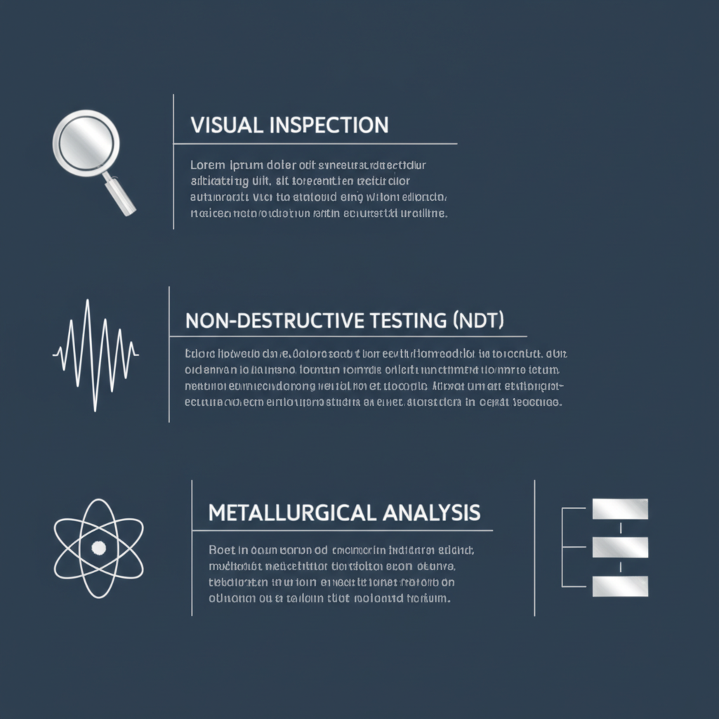
A successful failure investigation is a systematic, multi-disciplinary process that combines observation with advanced analytical techniques. The goal is to move beyond identifying the symptom—the crack or fracture—to uncovering the fundamental root cause. The process typically begins with a thorough visual examination of the failed component and the collection of all relevant service history, including operational loads, temperatures, and manufacturing data. This initial assessment helps to form a hypothesis about the failure mode.
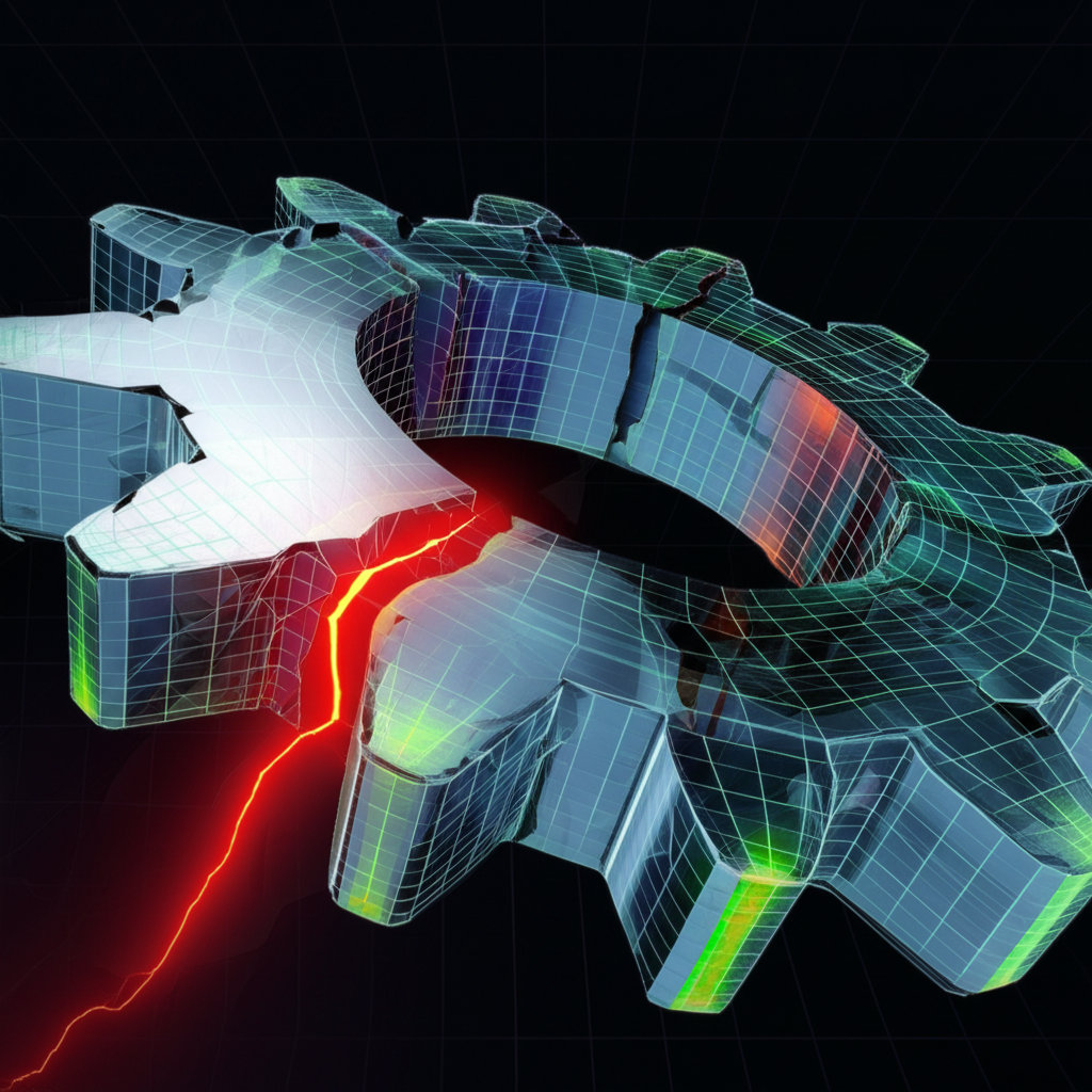
Following the initial assessment, a series of non-destructive and destructive tests are employed. Modern techniques like 3D optical scanning are increasingly used for precise geometrical analysis, allowing engineers to compare the failed part against its original CAD model to identify deformations or wear. This can reveal dimensional inaccuracies or areas of unexpected material loss or gain. Advanced Finite Element Modeling (FEM) is also a powerful tool, enabling virtual simulations of the forging process to identify areas of high stress or predict defects like underfills, folds, or trapped air pockets without destructive testing.
The core of the investigation often lies in metallurgical analysis. Samples are sectioned from the failed component, particularly near the fracture origin, and prepared for microscopic examination. Techniques like Scanning Electron Microscopy (SEM) are used to analyze the fracture surface (fractography), which reveals tell-tale signs of the failure mechanism, such as fatigue striations, brittle cleavage facets, or ductile dimples. Chemical analysis ensures the material composition meets specifications, while micro-hardness testing can detect surface decarburization or improper heat treatment. As demonstrated in the analysis of H13 forging dies, comparing the microstructure and hardness of failed parts to un-failed ones provides critical clues. Finally, mechanical tests, such as fracture toughness testing, quantify the material's ability to resist crack propagation, directly linking material properties to performance.
Case Study Deep Dive: From Cracked Automotive Components to Resolution
A compelling example of solving part failure comes from a supplier of automotive components experiencing persistent cracking in variable valve timing (VVT) plates. The parts, made from AISI 1045 carbon steel, were frequently returned cracked after being sent to a third-party for heat treatment. This issue forced the company to overproduce parts to meet its contractual obligations and to spend significant resources on 100% inspection, leading to wasted material and high costs. The supplier approached metallurgical experts to diagnose and resolve the recurring problem.
The investigation began with a forensic analysis of the failed parts. Metallurgists noted the components were excessively brittle. A close look at the microstructure revealed the parts had been carbonitrided, a surface hardening process. Further investigation up the supply chain uncovered a critical detail: the raw steel coils were being annealed in a nitrogen-rich environment. While annealing was necessary to prepare the steel for fine blanking, the combination of nitrogen from the annealing atmosphere and the aluminum used as a grain refiner in 1045 steel was problematic. This combination formed aluminum nitrides on the part surface.
The formation of aluminum nitrides created an extremely fine grain structure at the surface, which inhibited the steel's ability to harden correctly during the subsequent heat treatment. The original heat treater likely attempted to overcome this issue by using a more aggressive carbonitriding process, but this only succeeded in making the surface layer brittle without achieving the desired core hardness. The root cause was a fundamental incompatibility between the material chemistry and the specific processing steps used throughout the supply chain.
With the root cause identified, the solution was elegant yet effective. Since changing the annealing environment at the steel mill was not feasible, the team proposed a modification to the material itself. They recommended “spiking” the 1045 steel with a small amount of chromium. Chromium is a powerful alloying element that significantly increases the hardenability of steel. This addition compensated for the fine grain size caused by the aluminum nitrides, allowing the VVT plates to achieve full, uniform hardness through a standard hardening process without becoming brittle. The solution proved highly successful, eliminating the cracking issue entirely. This case underscores the importance of a holistic view of the manufacturing process and highlights how partnering with a specialized supplier can prevent such issues. For instance, companies focusing on high-quality automotive components, such as the custom forging services from Shaoyi Metal Technology, often maintain vertically integrated processes and IATF16949 certification to ensure material and process integrity from start to finish.
Root Cause Analysis: Common Culprits in Forged Component Failure
The failure of forged components can almost always be traced back to one of three primary areas: material deficiencies, process-induced defects, or issues related to design and service conditions. A thorough root cause analysis requires examining each of these potential contributors. Identifying the specific culprit is essential for implementing effective and lasting corrective actions.
Material Deficiencies are intrinsic to the raw stock used for forging. These include incorrect chemical composition, where alloying elements fall outside the specified range, or the presence of excessive impurities like sulfur and phosphorus, which can lead to embrittlement. Non-metallic inclusions, such as oxides and silicates, are another major concern. These microscopic particles can act as initiation sites for cracks, dramatically reducing the toughness and fatigue life of the component. The cleanliness of the steel, as noted in the analysis of H13 dies, has a direct effect on the material's toughness and isotropy.
Process-Induced Defects are introduced during the manufacturing stages, including forging and subsequent heat treatment. During forging, improper material flow can create defects like laps and folds. Incorrect forging temperatures can lead to hot tearing (if too hot) or surface cracking (if too cold). Heat treatment is another critical stage where errors can be catastrophic. An improper quenching rate can cause distortion or quench cracks, while incorrect tempering temperatures can result in a brittle microstructure. As the H13 die case study showed, tempering at a slightly higher temperature significantly improved fracture toughness by avoiding a tempered martensite embrittlement range.
Design and Service Conditions pertain to how the part is shaped and how it is used. Design flaws like sharp corners, inadequate fillet radii, or abrupt changes in section thickness create stress concentrations that act as natural starting points for fatigue cracks. Furthermore, the actual service conditions may exceed the design assumptions. Overloading, high-impact events, or exposure to corrosive environments can all lead to premature failure. Thermal fatigue, caused by cyclical heating and cooling, is a common failure mode for forging dies and other components used in high-temperature applications.
To provide a clear reference, the table below summarizes these common failure culprits:
| Cause Category | Specific Examples | Typical Indicators | Prevention Strategies |
|---|---|---|---|
| Material Deficiencies | Incorrect alloy composition, non-metallic inclusions, excessive impurities (S, P). | Brittle fracture, low toughness values, crack initiation at inclusions. | Strict material certification, use of premium/clean steel grades, incoming material inspection. |
| Process-Induced Defects | Forging laps/folds, quench cracks, improper tempering, surface decarburization. | Surface cracks, distorted geometry, hardness values outside specification. | Optimize forging preform design, precise control of heating and cooling rates, process simulation (FEM). |
| Design & Service | Sharp corners (stress risers), overloading, impact damage, thermal fatigue. | Fatigue cracks originating at design features, evidence of plastic deformation or wear. | Incorporate generous radii in design, conduct thorough stress analysis, select materials appropriate for the service environment. |
Frequently Asked Questions
1. What is the difference between a forging defect and a failure?
A forging defect is an imperfection or flaw within the component, such as a lap, crack, or inclusion, that is introduced during the manufacturing process. A failure, on the other hand, is the event where the component ceases to perform its intended function. A defect does not always lead to immediate failure, but it often acts as an initiation point for a crack that can grow under operational stress, eventually causing the part to fail.
2. Why is heat treatment so critical for forged components?
Heat treatment is a crucial step that transforms the microstructure of the steel after forging to achieve the desired mechanical properties, such as hardness, strength, and toughness. Forging refines the grain structure, but it is the subsequent heat treatment cycle—including processes like annealing, quenching, and tempering—that tailors these properties for the specific application. As seen in multiple case studies, improper heat treatment is one of the most common causes of premature failure in forged parts.
3. How does Finite Element Modeling (FEM) help in preventing forging failures?
Finite Element Modeling (FEM) is a powerful computer simulation technique that allows engineers to virtually model the entire forging process. By simulating material flow, temperature distribution, and stress development, FEM can predict potential problems before any metal is actually formed. It can identify areas at risk for defects like underfills, folds, or excessive strain, allowing designers to optimize the die geometry and process parameters to produce a sound, defect-free component.