 Small batches, high standards. Our rapid prototyping service makes validation faster and easier —

Blanking Die vs Piercing Die: Essential Technical Differences
TL;DR
Blanking and piercing are both high-speed shearing processes that use a punch and die to cut sheet metal. The essential difference lies in the intended product. In a blanking die operation, the piece that is punched out is the desired part, known as the 'blank'. Conversely, in a piercing die operation, the material punched out is scrap (a 'slug'), and the remaining sheet metal with the newly created hole is the desired part.
The Fundamental Shearing Process: How Blanking and Piercing Work
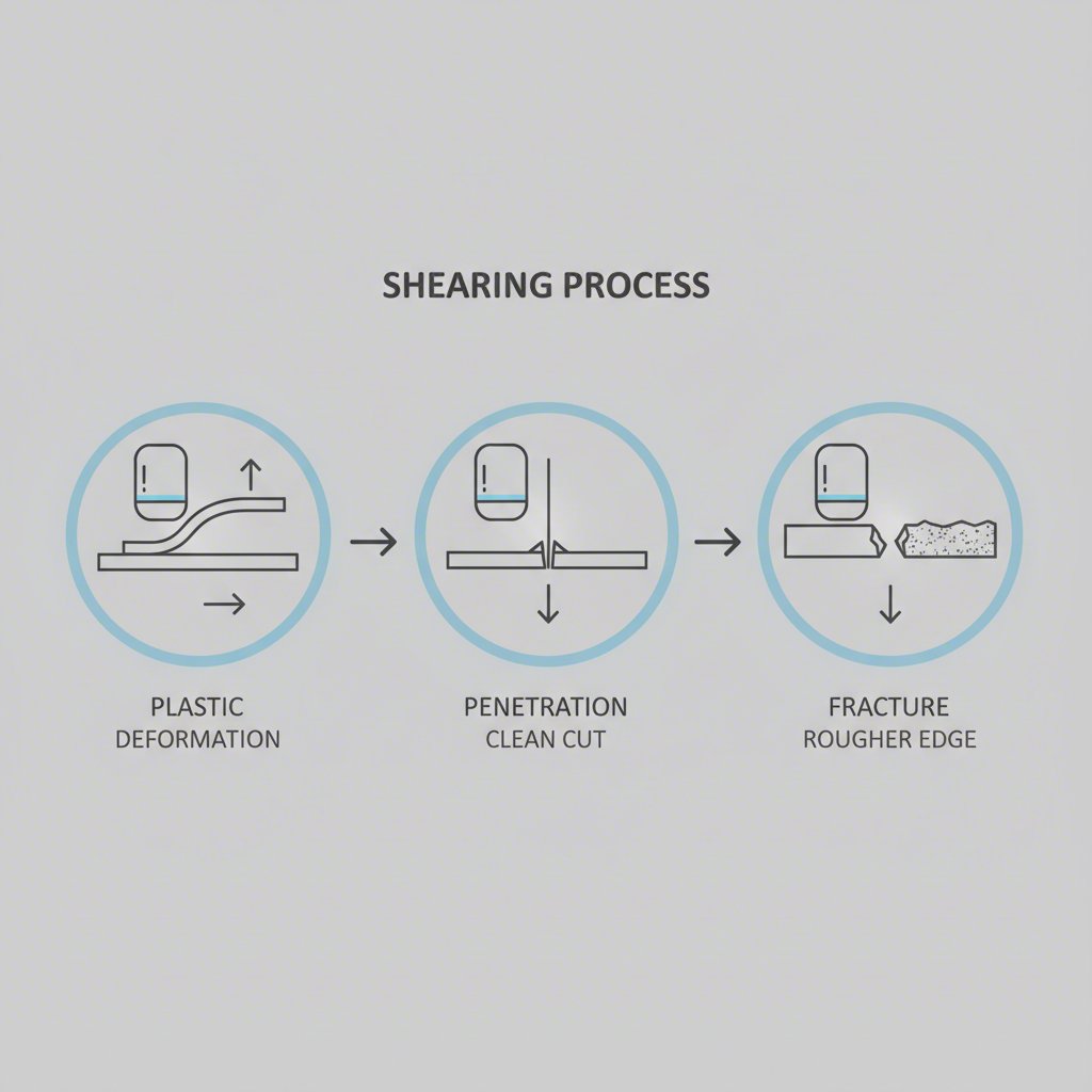
At their core, both blanking and piercing are mechanical shearing operations that separate a piece of metal from a larger sheet or strip. The process relies on the interaction between a punch (the male component) and a die (the female component). When a press activates, it drives the punch through the stock material and into the die opening, creating immense shearing force that cuts the metal. This fundamental action is identical for both processes and occurs in three distinct stages.
According to detailed analyses of the cutting cycle, the first stage is plastic deformation. As the punch contacts the material, it exerts force that exceeds the metal's elastic limit, causing it to deform permanently. The material bends into the die opening, creating a rounded edge known as 'die roll'. This initial compression is a characteristic feature of all stamped components. The quality and size of this die roll are often indicators of the tool's condition and the process parameters.
The second stage is penetration, which is the true shearing phase. As the press continues its stroke, the punch is forced deeper into the stock material. The cutting edges of the punch and die begin to shear the metal, creating a clean, burnished band on the cut edge of both the slug and the parent material. Under ideal conditions, this sheared band will constitute approximately one-third of the material's thickness. This phase requires immense force and is where the precision of the die components is most critical.
Finally, the process concludes with the fracture stage. The continued pressure from the punch causes stress concentrations that lead to fracturing. The fractures propagate from both the punch side and the die side of the material until they meet, completing the separation. This fracture creates the 'break' portion of the cut edge and can leave a small, rough edge known as a 'burr'. While the underlying physics are the same, the design intent of a blanking die versus a piercing die dictates which side of this cut becomes the final product.
Core Distinction: Workpiece vs. Scrap
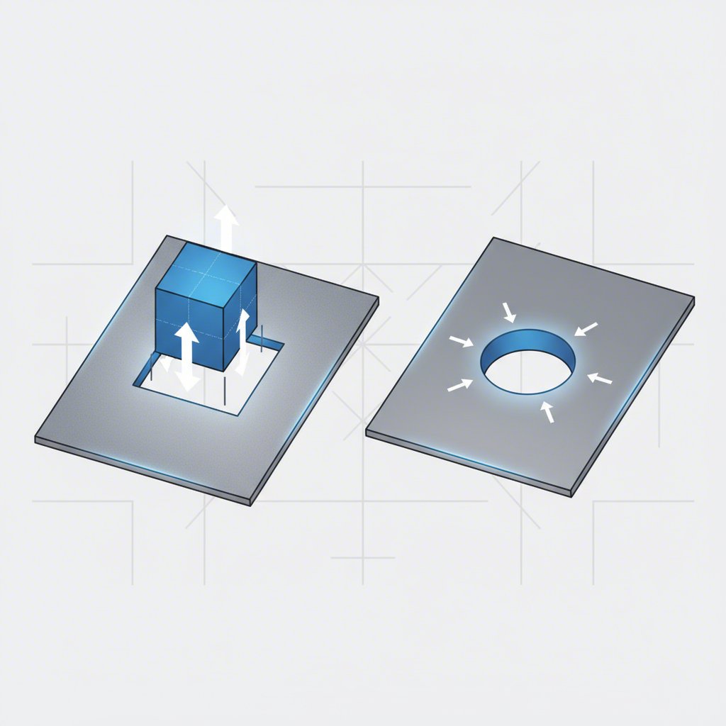
The primary and most critical distinction between a blanking die and a piercing die is their purpose—specifically, what part of the cut material is considered the product and what is discarded as scrap. Blanking creates the external features of a part, while piercing creates its internal features. This fundamental difference in intent dictates the design of the tooling and the focus of quality control.
In a blanking operation, the piece punched out of the stock material is the desired workpiece. The surrounding material, known as the scrap strip or skeleton, is discarded. The entire process is designed to ensure the dimensional accuracy and edge quality of the punched-out 'blank'. For example, manufacturing coins, washers, or flat gear blanks are all blanking operations because the small, separated piece is the final product.
Conversely, a piercing operation is performed to create a hole or opening in a workpiece. In this case, the material that is punched out—the slug—is considered scrap. The larger sheet or part, now containing a precisely located hole, is the desired product. Creating screw holes in a computer chassis, ventilation slots in an enclosure, or locating holes in a bracket are all examples of piercing. The focus is on the accuracy of the hole's size, shape, and position.
This distinction has a direct impact on tool design. For a blanking die, the die opening's dimensions determine the final size of the blank. For a piercing die, the punch's dimensions determine the final size of the hole. This subtle but crucial difference guides the toolmaker in applying manufacturing tolerances to either the punch or the die to achieve the required part accuracy. If you need the piece that is cut out, you use blanking. If you need a hole in a larger piece, you use piercing.
| Process | Desired Part | Scrap Material | Typical Application |
|---|---|---|---|
| Blanking | The punched-out piece (the 'blank') | The remaining stock strip | Creating washers, coins, electrical laminations, gear blanks |
| Piercing | The stock material with a hole in it | The punched-out piece (the 'slug') | Creating screw holes, vents, slots, and locating features |
Die Design and Clearance: The Technical Details
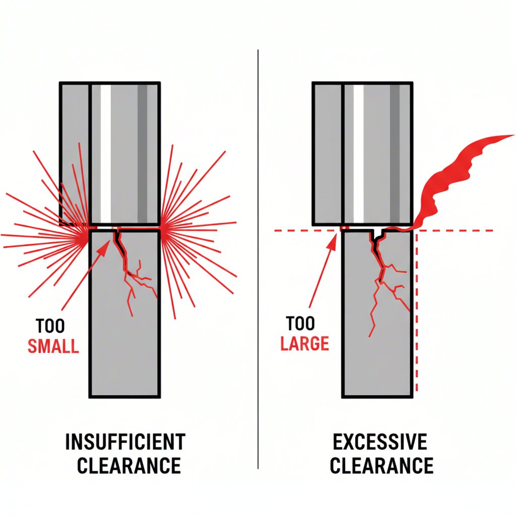
Beyond the core purpose, the technical design of the die, particularly the cutting clearance, is a critical factor that differentiates high-quality operations. Cutting clearance is defined as the space between the cutting edge of the punch and the corresponding cutting edge of the die. Proper clearance is essential for the quality of the finished part and the longevity of the tool itself. The selection of this clearance depends on the material type, thickness, and desired edge characteristics.
Incorrect clearance leads to predictable defects. If the clearance is excessive, the material is pulled into the die opening before it shears, resulting in a large, rounded die roll and a significant burr. The cut band becomes very small, and the part's edge quality is poor. If the clearance is insufficient, it creates undue stress on both the material and the tooling. This can cause secondary shear (a second burnished band on the fracture face), requires much higher punching force, and leads to rapid wear of the punch and die cutting edges.
The optimal clearance is a balance between edge quality and tool life. General guidelines for steel are often expressed as a percentage of the material thickness per side:
- Precision Stamping: For high-quality shear surfaces with minimal burrs, clearance is typically small, around 5% of the material thickness.
- Conventional Stamping: To extend die life and reduce punching force, clearance is slightly larger, often 8%-10% of the material thickness.
Achieving these precise tolerances in tool manufacturing requires significant expertise. Leading manufacturers of custom tooling, such as Shaoyi (Ningbo) Metal Technology Co., Ltd., specialize in creating high-precision automotive stamping dies where controlling these parameters is essential for producing millions of components with consistent quality. Another key design feature is angular clearance, a slight taper in the die opening that allows the blank or slug to pass through without jamming, relieving internal pressure after the cut.
Industrial Context: Blanking, Piercing, and Punching Explained
In industrial settings, the terms 'piercing' and 'punching' are often used interchangeably, which can cause confusion. While blanking is a distinct process, punching serves as a broader category that functionally overlaps with piercing. Understanding this nuance is key to clear communication in a manufacturing environment.
Punching is the general term for a process that uses a punch and die to create a feature in sheet metal. However, in its most common technical usage, punching refers to an operation where the removed material is scrap. By this definition, punching is functionally identical to piercing. Both processes create holes, slots, or other internal features in a workpiece, and the slug is discarded.
The key is to always consider the intent. A simple analogy helps clarify the relationship: if you use a standard office hole punch on a piece of paper to put it in a binder, you are piercing or punching holes; the paper is the part and the small paper circles are scrap. If you were collecting those small circles to use as confetti, you would be blanking the confetti; the circles are the part and the paper sheet is the scrap.
To summarize the relationship:
- Blanking: The punched-out material is the desired product.
- Piercing: The material remaining after the punch creates a hole is the desired product.
- Punching: A general term often used synonymously with piercing, where the goal is to create a hole and the removed material is scrap.
Therefore, when discussing a metal stamping operation, it is crucial to clarify which part of the material is the final product. This ensures that the die is designed correctly and that everyone involved, from the engineer to the toolmaker, understands the objective of the process.
Frequently Asked Questions
1. What is the difference between piercing and blanking?
The fundamental difference is the desired output. In blanking, the piece cut out from the sheet metal is the final product, used to create the external features of a component. In piercing, the material cut out is scrap, and the goal is to create an internal hole or shape in the remaining sheet metal.
2. What is a blanking die?
A blanking die is a specialized metalworking tool composed of a punch and a die set. It is used in a press to perform a shearing operation that cuts out flat pieces of stock material. The defining characteristic is that the die, in conjunction with the punch, is designed to produce a specific shape (the 'blank') that will be used as the final part.
3. What is the punch and die clearance for blanking and piercing?
Punch and die clearance is the gap between the punch and die cutting edges. The optimal clearance varies by material thickness and desired quality. For precision work with minimal burrs, clearance is typically around 5% of the material's thickness per side. For conventional operations where extending tool life is a priority, a larger clearance of 8%-10% is common.
4. What's the difference between blanking and punching?
While blanking produces a usable part from the material that is cut out, punching is generally used as a synonym for piercing. In a punching operation, the goal is to create a hole in the workpiece, and the material that is removed is considered scrap. The key distinction is always whether the punched-out piece or the remaining sheet is the intended product.