 Small batches, high standards. Our rapid prototyping service makes validation faster and easier —

Automotive Stamping Tolerance Standards: A Precision Guide
TL;DR
Automotive stamping tolerance standards typically range from ±0.1 mm to ±0.25 mm for standard features, while precision stamping can achieve tighter limits of ±0.05 mm. These deviations are governed by global frameworks like ISO 2768 (general tolerances), DIN 6930 (stamped steel parts), and ASME Y14.5 (GD&T). Engineers must balance these precision requirements with material properties—such as springback in high-strength steel—and cost implications, as tighter tolerances exponentially increase manufacturing complexity.
Global Industry Standards for Automotive Stamping
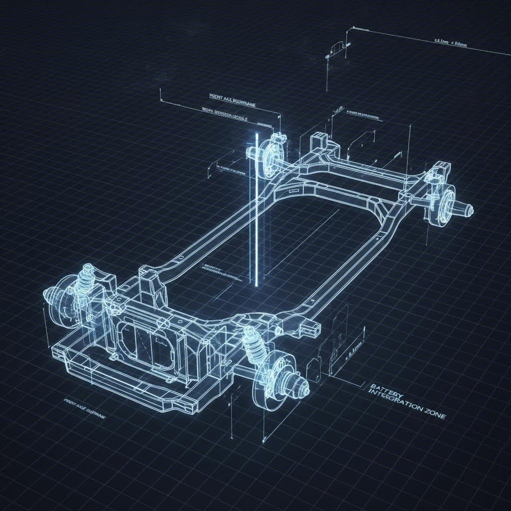
In the automotive supply chain, ambiguity is the enemy of quality. To ensure parts fit seamlessly into Body-in-White (BIW) assemblies or engine compartments, manufacturers rely on a hierarchy of international standards. These documents define not just the allowable linear deviations, but also the geometric integrity of the part.
Key Standards: ISO vs. DIN vs. ASME
While OEM-specific standards (like GM’s or Toyota’s internal specs) often take precedence, three global frameworks form the baseline for automotive stamping:
- ISO 2768: The most ubiquitous standard for general machining and sheet metal. It is divided into four tolerance classes: fine (f), medium (m), coarse (c), and very coarse (v). Most automotive structural parts default to the "medium" or "coarse" class unless critical function dictates otherwise.
- DIN 6930: Specifically tailored for stamped steel parts. Unlike general machining standards, DIN 6930 accounts for the unique behaviors of sheared metal, such as die roll and fracture zones. It is frequently cited in European automotive blueprints.
- ASME Y14.5: The gold standard for Geometric Dimensioning and Tolerancing (GD&T). In automotive design, linear tolerances often fail to capture functional requirements. ASME Y14.5 uses controls like Profile of Surface and Position to ensure parts mate correctly in complex assemblies.
Understanding the distinction between these standards is critical. For instance, ADH Machine Tool notes that precision stamping can achieve tolerances seldom seen in other processes, but this requires strict adherence to the correct tolerance class during the design phase.
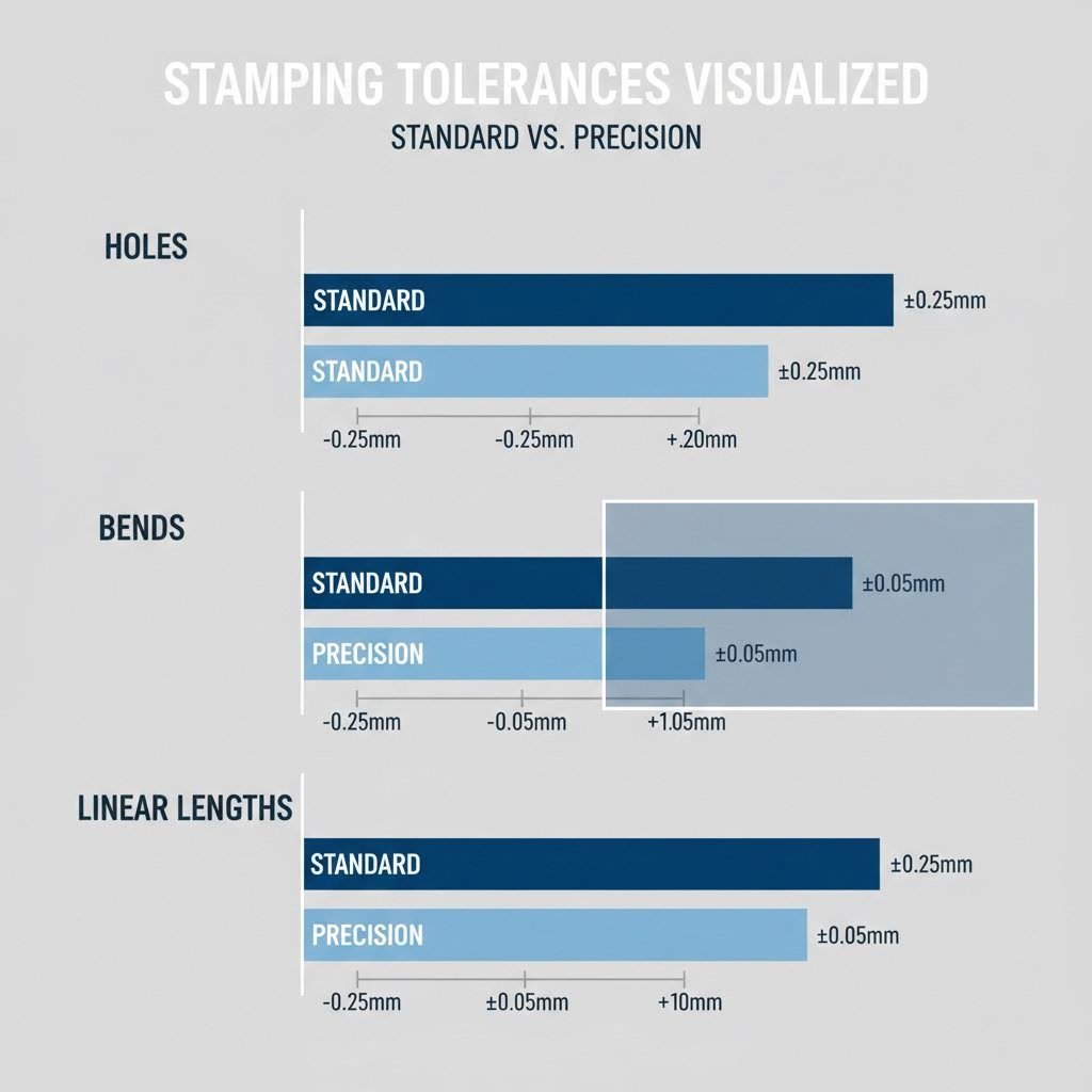
Typical Automotive Stamping Tolerance Ranges
Engineers often ask, "What is the tightest tolerance I can specify?" While ±0.025 mm is possible with specialized tooling, it is rarely cost-effective. The table below outlines achievable ranges for standard vs. precision automotive stamping.
| Feature | Standard Tolerance | Precision Tolerance | Notes |
|---|---|---|---|
| Linear Dimensions (<100 mm) | ±0.1 mm – ±0.2 mm | ±0.05 mm | Depends heavily on material thickness. |
| Hole Diameter | ±0.05 mm | ±0.025 mm | Punched holes hold tighter specs than formed features. |
| Hole-to-Hole Position | ±0.15 mm | ±0.08 mm | Critical for multi-point assembly alignment. |
| Bends (Angles) | ±1.0° | ±0.5° | Highly sensitive to material springback. |
| Flatness | ±0.5% of Length | ±0.2% of Length | Requires secondary leveling for precision. |
| Burr Height | < 10% of Thickness | < 5% of Thickness | Deburring processes may be required. |
It is vital to recognize that tighter tolerances require more expensive tooling and frequent maintenance. Protolabs highlights that stacking tolerances—where small deviations in bends and holes accumulate—can lead to assembly failures if not calculated correctly during the design phase.
Material-Specific Tolerance Factors
Material selection is the single biggest variable affecting stamping accuracy. In modern automotive engineering, the shift toward lightweighting has introduced materials that are notoriously difficult to control.
High Strength Steel (HSS) vs. Aluminum
Advanced High Strength Steel (AHSS) and Ultra High Strength Steel (UHSS) are essential for safety cages, but they exhibit significant "springback"—the tendency of metal to return to its original shape after forming. Achieving a ±0.5° bend tolerance in AHSS requires complex die engineering and often overbending the material to compensate.
Aluminum, used extensively in body panels for weight reduction, presents its own challenges. It is softer and more prone to galling or surface defects. According to the High Strength Steel Stamping Design Manual, controlling springback in these materials requires advanced simulation and precise die compensation strategies.
For OEMs and Tier 1 suppliers bridging the gap from prototype to mass production, partner capabilities matter as much as material science. Manufacturers leveraging Shaoyi Metal Technology’s comprehensive stamping solutions benefit from IATF 16949-certified processes that manage these material behaviors, ensuring consistent tolerances from 50 prototypes up to millions of production parts.
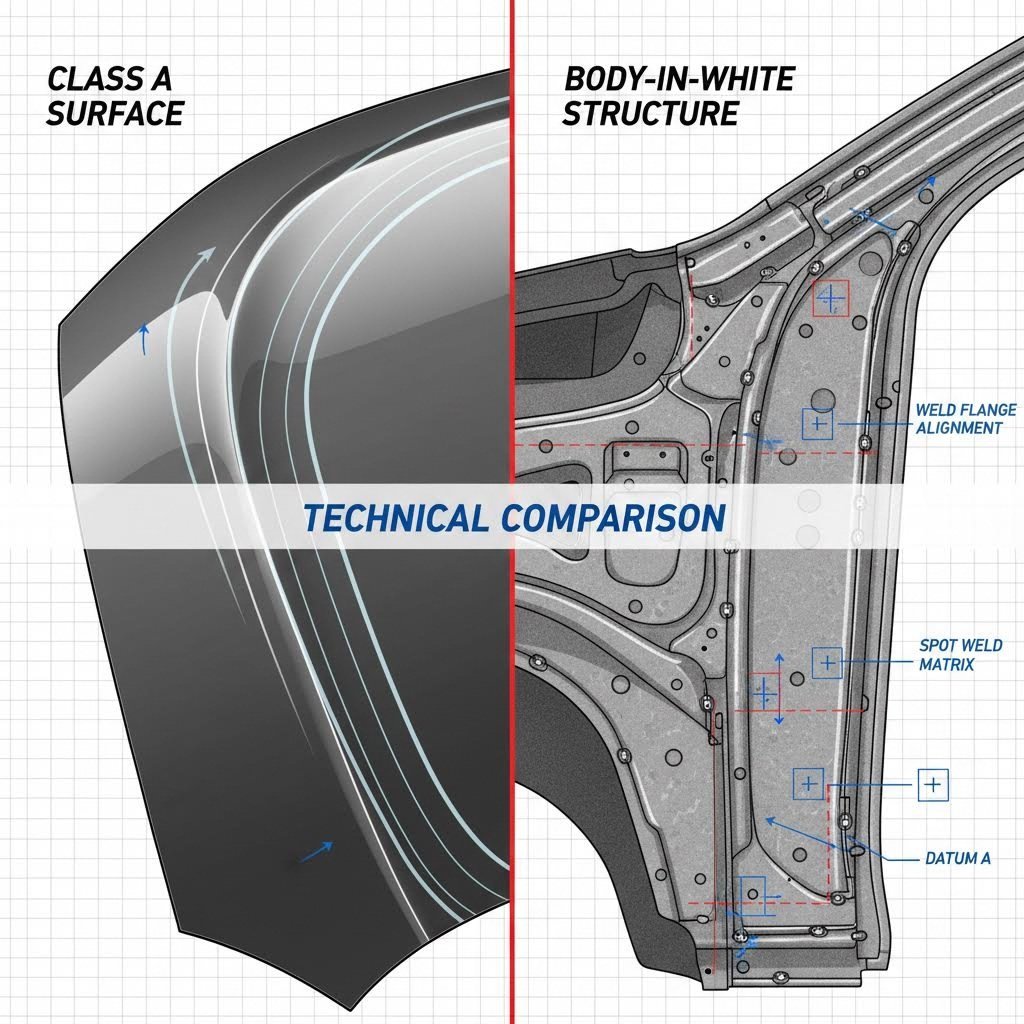
Class A Surface vs. Structural (BIW) Tolerances
Not all automotive deviations are treated equally. The allowable tolerance depends heavily on the part's visibility and function.
Class A Surfaces
"Class A" refers to the visible outer skin of the vehicle—hoods, doors, and fenders. Here, the tolerance focus shifts from simple linear dimensions to surface continuity and defect-free finishes. A localized depression of even 0.05 mm might be unacceptable if it creates a visible distortion in the paint reflection. Stamping these parts requires pristine dies and rigorous maintenance to prevent "pimples" or draw lines.
Body-in-White (BIW) Structures
Structural components hidden under the skin focus on fit and function. The primary concern is weld point alignment. If a subframe bracket is off by ±0.5 mm, the robotic welder may miss the flange, compromising chassis rigidity. Talan Products explains that while structural parts may have looser cosmetic standards, their positional tolerances are non-negotiable for automated assembly lines.
Design for Manufacturing (DFM) Rules
To ensure specified tolerances are actually manufacturable, designers should adhere to proven DFM guidelines. Ignoring these physics-based rules often results in parts that cannot hold tolerance.
- Hole-to-Edge Distance: Keep holes at least 1.5x to 2x material thickness away from edges. Placing holes too close allows the metal to bulge, distorting the hole shape and violating diameter specs.
- Bend Radii: Avoid sharp internal corners. A minimum bend radius equal to the material thickness (1T) prevents stress cracking and inconsistent springback.
- Feature Spacing: Sheet metal fabrication experts recommend keeping features away from the bend zone. Distortions near the bend line make it impossible to hold tight positional tolerances for holes or slots.
Achieving Precision in Production
Automotive stamping tolerance standards are not arbitrary numbers; they are a balance between design intent, material physics, and manufacturing reality. By referencing standards like ISO 2768 and DIN 6930, and understanding the specific constraints of materials like HSS, engineers can design parts that are both high-performance and cost-effective to produce.
Frequently Asked Questions
1. What is the standard general tolerance for automotive stamping?
The industry standard for general linear dimensions typically falls between ±0.1 mm and ±0.25 mm. This range (Medium Class m under ISO 2768) is sufficient for most non-critical structural features, balancing cost with assembly requirements.
2. How does material thickness affect stamping tolerances?
Thicker materials generally require looser tolerances. As a rule of thumb, linear tolerances often expand as thickness increases due to the larger volume of metal being displaced. For example, a bracket under 1 mm thick might hold ±0.1 mm, while a 4 mm thick chassis part might require ±0.3 mm.
3. Why is springback a problem for stamping tolerances?
Springback is the elastic recovery of metal after bending. It causes the final angle to deviate from the die angle. High-strength steels exhibit significant springback, requiring designers to specify wider angular tolerances (e.g., ±1.0°) or manufacturers to use advanced compensation dies.