 Small batches, high standards. Our rapid prototyping service makes validation faster and easier —

Automotive Stamping Plant Layout: Optimizing Workflow & Facility Design
TL;DR
Automotive stamping plant layout involves the strategic engineering of spatial workflows to transform raw sheet metal coils into finished vehicle body components with maximum efficiency. A well-optimized facility integrates five critical zones: climate-controlled coil storage, washing units, the primary press shop (utilizing Tandem, Transfer, or Progressive lines), automated scrap handling systems, and outbound logistics for sub-assemblies. By aligning material flow from receiving to shipping—often validated through digital twin simulation—plant managers can minimize bottleneck risks and ensure high-throughput production.
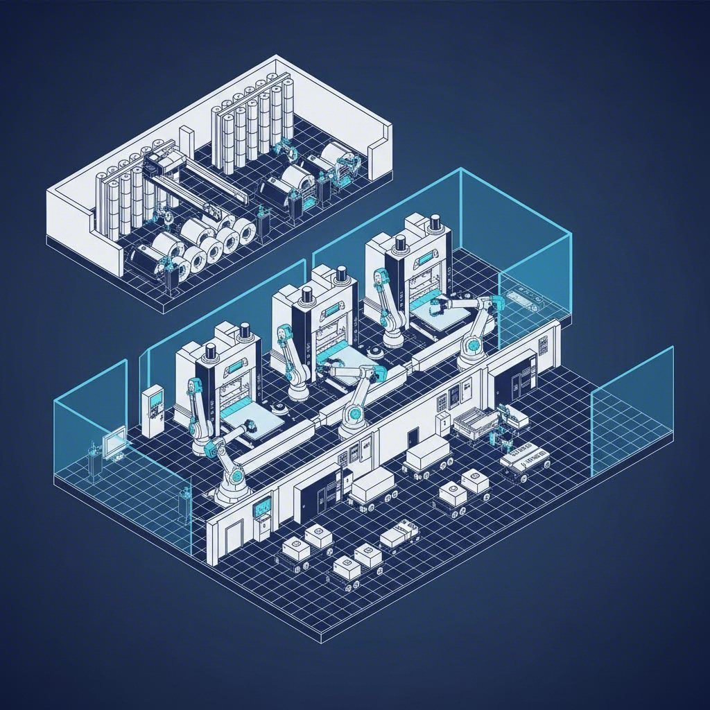
Macro-Level Facility Zones & Workflow Architecture
Designing an automotive stamping plant requires a rigorous approach to material flow, treating the facility not just as a collection of machines, but as a cohesive system. According to industry leaders like Schuler, the layout must reflect a production philosophy that prioritizes minimized handling and linear progression. The most efficient layouts typically follow a straight-line or U-shaped flow to reduce transit times between the five core operational zones.
1. Raw Material Receiving and Coil Storage
The process begins at the receiving bay, designed to accommodate heavy rail or truck deliveries. Since surface quality is paramount for outer body panels, this zone requires strict climate control to prevent oxidation. Data from simulation studies suggests maintaining a buffer of varying steel grades—often ensuring 6+ rolls are on hand for immediate scheduling—to prevent line starvation. Best practices dictate positioning high-capacity overhead cranes immediately above unloading docks to transfer coils to storage racks without ground-level interference.
2. Washing and Blanking
Before metal reaches the main presses, it passes through washing and blanking lines. This intermediate zone is critical for removing dust and applying lubrication. In modern layouts, blanking lines (which cut coils into flat sheets) are positioned adjacent to the press shop entrance to feed the main lines directly. This proximity reduces the travel distance for heavy blanks, which are often transported via automated guided vehicles (AGVs) or pallet systems.
3. The Press Shop Core
The heart of the facility houses the heavy stamping lines. The layout here is dictated by the type of press technology (Tandem vs. Transfer) and requires massive reinforced foundations. Aisles must be wide enough not just for operation, but for die carts and maintenance equipment. Efficient layouts often group presses by tonnage and bolster size to streamline die changeovers and maintenance schedules.
4. Assembly and Body-in-White (BIW) Integration
Post-stamping, parts often move to a welding or sub-assembly zone. Here, stamped panels are joined to form hoods, doors, or structural components. Integrating this zone closely with the press output reduces the need for intermediate warehousing. The flow then terminates at Shipping, where finished sub-assemblies are racked and loaded for transport to the main body shop.
Press Line Configuration: Tandem, Transfer, and Progressive
Selecting the right press line configuration is the single most significant factor influencing the physical footprint of the plant. Planners must balance production volume, part complexity, and facility size constraints.
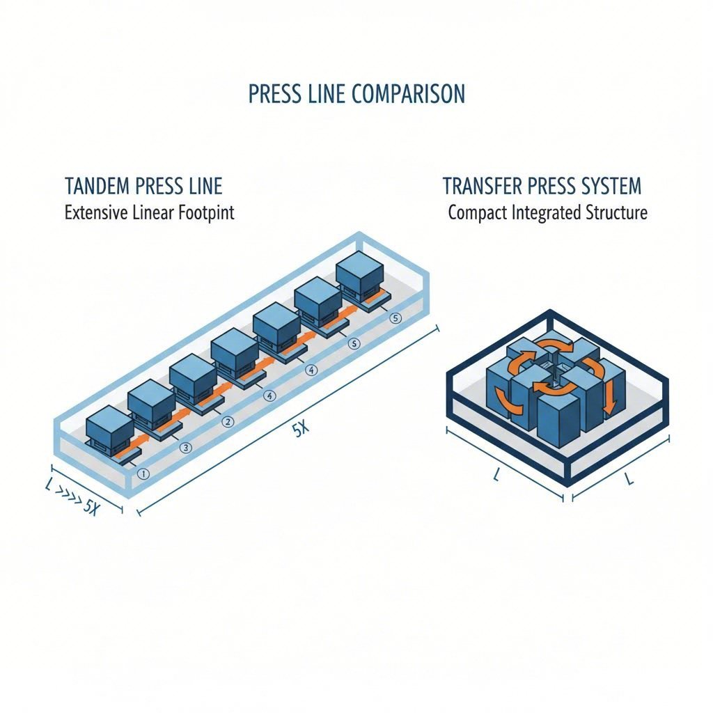
Tandem Press Lines
Tandem lines consist of a series of individual presses arranged in a line. A robotic arm or transfer system moves the part from one press to the next for each operation (drawing, trimming, piercing).
Layout Impact: These require significant linear floor space. However, they offer flexibility; if one press requires maintenance, the line might still operate in a limited capacity, or individual presses can be swapped out.
Transfer and Progressive Die Presses
Transfer presses house multiple operations within a single, massive bed, using rails to move parts internally. Progressive die presses feed a continuous coil through a single machine where multiple operations occur sequentially.
Layout Impact: These are more compact than tandem lines but require heavier singular foundations. They are ideal for high-volume production of smaller structural parts. For manufacturers scaling from prototype to mass production, selecting the right machinery is crucial. Partners like Shaoyi Metal Technology demonstrate how leveraging diverse press capabilities—ranging up to 600 tons—enables the production of precision components like control arms and subframes with IATF 16949 adherence, bridging the gap between initial design and high-volume output.
| Feature | Tandem Line | Transfer Press | Progressive Die |
|---|---|---|---|
| Space Requirement | High (Long linear footprint) | Medium (Compact, heavy load) | Low (Single machine footprint) |
| Throughput Speed | Medium | High | Very High |
| Flexibility | High (Inter-press adjustments) | Medium (Complex die changes) | Low (Dedicated high-volume) |
| Typical Application | Large exterior panels (Hoods, Roofs) | Complex structural parts | Small brackets, reinforcements |
Scrap Management and Auxiliary Logistics
An often-overlooked aspect of stamping plant design is the management of "offal" or scrap metal. Stamping operations generate tons of scrap daily, and inefficient removal can halt production instantly.
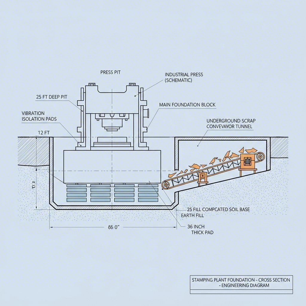
Underground vs. Surface Conveyors
High-volume facilities typically utilize underground scrap tunnels located directly beneath the press beds. Metal trimmings fall through chutes onto vibrating conveyors that transport the scrap to a central baling room, isolating the noise and dust from the main floor. For existing facilities where excavation is impossible, surface-level magnetic conveyors are used, though they consume valuable floor space and can obstruct forklift paths.
Coil and Die Logistics
Logistical routes must be separated to prevent cross-traffic accidents. Establish dedicated lanes for heavy forklifts carrying coils and separate paths for tuggers moving finished parts. Modern layouts increasingly rely on automated storage and retrieval systems (AS/RS) for dies, positioning heavy tooling near the presses to minimize changeover times (SMED).
Digital Twin and Simulation-Driven Optimization
Before pouring concrete, modern facility planning relies heavily on simulation. Creating a "Digital Twin" allows engineers to stress-test the layout virtually. Resources like Simul8 highlight the value of discrete event simulation to predict bottlenecks. By modeling shift patterns, crane speeds, and press stroke rates, planners can visualize where material piles up.
For example, a simulation might reveal that a single overhead crane is insufficient to service three tandem lines during peak changeover times, justifying the investment in a second crane or a dedicated die-staging bay. This analytical approach moves layout design from static CAD drawings to dynamic, performance-based engineering.
Infrastructure and Safety Considerations
The physical infrastructure of a stamping plant must withstand immense dynamic loads. Press pits are often isolated from the main building foundation using vibration-dampening materials to prevent shock waves from affecting sensitive measurement equipment or adjacent offices.
Safety Zoning
Safety is not an afterthought but a layout constraint. Robotic cells in tandem lines must be enclosed in safety fencing with interlocked gates. Light curtains are standard for manual load zones. Furthermore, the layout must account for ergonomic maintenance access—ensuring there is sufficient overhead clearance for cranes to lift dies and ample floor space for technicians to service hydraulic units without entering the active automation zone.
Conclusion: The Strategic Value of Layout
A well-executed automotive stamping plant layout is a competitive asset that directly impacts throughput, safety, and cost per unit. By strategically aligning the five core zones—from receiving to shipping—and selecting the appropriate press configurations, manufacturers can achieve a seamless flow of material. The integration of underground scrap handling and simulation-based planning further ensures that the facility remains resilient to demand fluctuations. Ultimately, the spatial organization of the plant dictates its operational ceiling, making initial design and continuous optimization critical for long-term success.
Frequently Asked Questions
1. What is the largest stamping plant in operation?
While many global manufacturers operate massive facilities, the Sterling Stamping Plant operated by Stellantis is recognized as the largest stamping plant in the world. It supplies millions of parts annually to assembly plants across the U.S., Canada, and Mexico, serving as a benchmark for high-volume facility layout and logistics.
2. What are the main types of metal stamping processes?
The four primary types of metal stamping found in automotive layouts are progressive die stamping, transfer die stamping, deep draw stamping, and fineblanking. Each requires specific press configurations and spatial arrangements. Progressive and transfer stamping are most common for high-volume body and structural parts, while deep draw is essential for forming cup-shaped components.
3. How does the stamping process fit into general vehicle production?
Stamping is typically the first step in the vehicle manufacturing lifecycle. Enormous steel sheets are pressed into body panels (doors, hoods, fenders) and structural supports. These stamped parts—often referred to as sub-assemblies—are then shipped to the Body Shop (or Body-in-White), where they are welded together to form the vehicle's rigid frame before painting and final assembly.