 Small batches, high standards. Our rapid prototyping service makes validation faster and easier —

Automotive Stamping Die Design Guidelines: Standards & Clearances
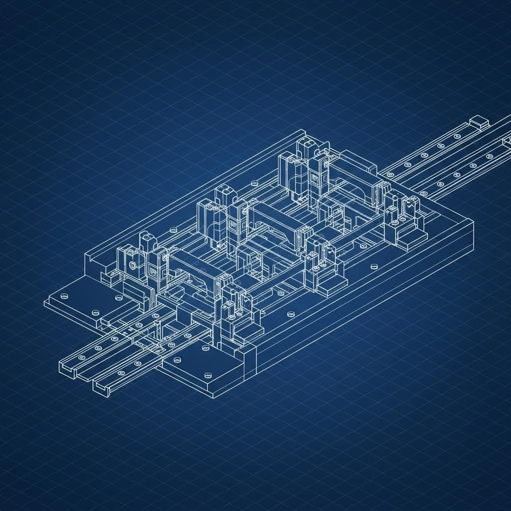
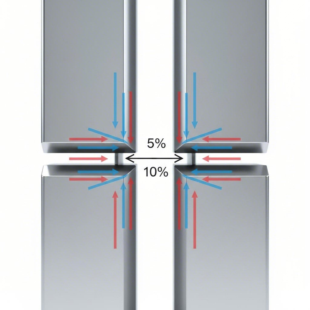
<h2>TL;DR</h2><p>Automotive stamping die design is the engineering discipline that balances material formability with high-volume tooling durability. Key standards include optimizing cutting clearances based on material thickness (typically 6–8% for mild steel and 14–16% for AHSS), selecting robust tool steels like matrix alloys to prevent galling, and engineering precise scrap management systems with 30° slide angles. Success requires a simulation-first approach using FEA to predict springback and validate geometry before any metal is cut.</p><h2>Automotive Die Process Selection and Fundamentals</h2><p>Selecting the correct die architecture is the first critical decision in automotive manufacturing, dictating both the initial tooling investment and the long-term piece price. The choice generally falls between Progressive, Transfer, and Line dies, determined by production volume, part complexity, and the raw material's mechanical properties.</p><h3>Progressive vs. Transfer Die Decision Matrix</h3><p>Progressive dies are the standard for high-volume, small-to-medium complex parts like brackets and reinforcements. In this process, a continuous metal strip feeds through multiple stations where operations (piercing, bending, coining) occur simultaneously. Conversely, transfer dies are necessary for larger structural components—such as cross members or pillars—that require freedom of movement between stations or use unconnected blanks.</p><table><thead><tr><th>Feature</th><th>Progressive Die</th><th>Transfer Die</th></tr></thead><tbody><tr><td><strong>Ideal Volume</strong></td><td>High (500,000+ parts/year)</td><td>Medium to High (Flexible)</td></tr><tr><td><strong>Part Size</strong></td><td>Small to Medium (fitting strip width)</td><td>Large, deep-drawn, or irregular</td></tr><tr><td><strong>Material Usage</strong></td><td>Lower (carrying strip required)</td><td>Higher efficiency (nested blanks)</td></tr><tr><td><strong>Cycle Speed</strong></td><td>Fastest (SPM 60–100+)</td><td>Slower (limited by transfer arm speed)</td></tr></tbody></table><h3>Design for Manufacturability (DFM) and Scalability</h3><p>Effective DFM requires early collaboration between product designers and tool engineers. Critical checks include verifying hole-to-edge ratios (minimum 1.5x material thickness) and bend radii to prevent cracking in High-Strength Low-Alloy (HSLA) steels. This phase also determines the press requirements.</p><p>For programs transitioning from development to mass production, partnering with a manufacturer capable of scaling is vital. Companies like <a href="https://www.shao-yi.com/auto-stamping-parts/">Shaoyi Metal Technology</a> bridge this gap by offering rapid prototyping (delivering 50 parts in as few as five days) while maintaining the infrastructure, such as 600-ton presses and IATF 16949 certification, needed for million-part production runs. Evaluating a partner's capacity to handle both trial phases and full-scale stamping ensures design intent is preserved throughout the product lifecycle.</p><h2>Critical Design Parameters: Clearances and Geometry</h2><p>Precision in die geometry is the difference between a clean shear and a burred edge. The most strictly controlled parameter in automotive stamping die design is the cutting clearance—the gap between the punch and the die button. Insufficient clearance increases press load and tool wear, while excessive clearance causes roll-over and heavy burrs.</p><h3>The 6–16% Clearance Rule</h3><p>Modern standards have shifted away from the traditional tight clearances used for mild steel. As automotive materials advance toward higher tensile strengths, clearance percentages must increase to allow for the proper "snap" or fracture of the metal. Engineering guidelines typically recommend the following clearance per side (as a percentage of material thickness):</p><ul><li><strong>Mild Steel / Aluminum:</strong> 6–8%</li><li><strong>Stainless Steel (300/400 Series):</strong> 10–12%</li><li><strong>Advanced High-Strength Steel (AHSS):</strong> 14–16%+</li></ul><h3>Scrap Management Standards</h3><p>Poor scrap shedding is a leading cause of die damage. If a slug pulls back onto the die surface (slug pulling), it can destroy the strip or the tool on the next hit. According to <a href="https://www.harsle.com/automotive-stamping-die-design-standards/?srsltid=AfmBOorEwqIzOHRfN5lRTGiYpvKY_j2lWEO1MZFzIL-4K0LKbuN4TO9A">HARSLE's design standards</a>, scrap management must be engineered with specific slide angles to ensure gravity assists the removal process:</p><ul><li><strong>Primary Slide Angle (Internal):</strong> Minimum 30°</li><li><strong>Secondary Slide Angle (External):</strong> Minimum 25°</li><li><strong>Funnel/Chute Angle:</strong> Greater than 50° preferred</li></ul><p>Additionally, the leakage waste chute should be designed at least 30mm larger than the maximum scrap dimension to prevent jamming. For Z-shaped or complex scrap, spring-loaded ejector pins (thimbles) should be integrated to rotate and dislodge the waste efficiently.</p><h2>Advanced Material Selection and Tool Steels</h2><p>The durability of the die itself is paramount, especially when stamping abrasive AHSS materials rated at 1200 MPa or higher. The industry standard tool steels—A2 and D2—are often insufficient for modern automotive applications due to chipping and galling risks.</p><h3>High-Performance Metallurgy</h3><p>For high-wear components, engineers are increasingly specifying <strong>8% Chromium steels</strong> and <strong>Matrix High-Speed Steels</strong>. These materials offer a superior balance of toughness and wear resistance compared to traditional D2. In hot stamping applications, where thermal conductivity is as critical as hardness, H13 tool steel is the standard choice to manage the rapid heating and cooling cycles.</p><h3>Surface Coatings and Treatments</h3><p>To further extend tool life, surface treatments are applied to reduce the coefficient of friction. Simple TiCN coatings are being replaced by duplex treatments—a process where the tool steel is first plasma ion nitrided to harden the substrate, followed by a nanocrystal coating (such as those developed by <a href="https://www.metalformingmagazine.com/article/?/finishing/coating/stamping-tooling-die-design-materials-coatings-and-setup">Phygen</a>) to prevent adhesion. This "duplex" approach ensures the hard coating does not crack due to a soft substrate underneath (the "egg-shell effect").</p><h2>Deep Draw and Complex Form Guidelines</h2><p>Deep drawing—forming a sheet into a hollow shape like an oil pan or sensor housing—requires strict adherence to reduction ratios to prevent splitting. The Limiting Draw Ratio (LDR) dictates how much material can flow into the die without failure.</p><h3>Reduction Ratios and Defects</h3><p>A general rule of thumb for cylindrical draws is to limit the diameter reduction in each station. Aggressive reductions thin the material wall excessively, leading to tearing.</p><ol><li><strong>First Draw:</strong> Maximum 40–45% reduction from blank diameter.</li><li><strong>Second Draw:</strong> 20–25% reduction.</li><li><strong>Subsequent Draws:</strong> 15% reduction.</li></ol><p>Common defects include <strong>wrinkling</strong> (flange instability) and <strong>tearing</strong> (excessive tension). According to <a href="https://www.transmatic.com/ultimate-guide-to-deep-draw-metal-stamping/">Transmatic's guide</a>, controlling material flow with draw beads and optimizing corner radii (ideally 10x material thickness) are essential strategies. Simulation software is often used to calculate the precise blank shape required to achieve the final net shape without excessive trimming.</p><h2>Die Simulation, Standards, and Quality Control</h2><p>The "tryout" phase of the past—grinding and welding until the part fits—is too costly for modern automotive timelines. Today, die design relies on <strong>Incremental Forming Simulation</strong> (using software like AutoForm or Dynaform) integrated directly into the CAD environment.</p><p>Simulation allows designers to visualize sheet thinning and predict <strong>springback</strong>—the tendency of metal to return to its original shape after forming. For AHSS parts, springback can be significant. The simulation data enables designers to engineer "over-bend" features into the die surface, compensating for the material's elastic recovery before the tool is ever built.</p><p>Finally, rigorous Quality Control protocols such as Geometric Dimensioning and Tolerancing (GD&T) apply to the die components themselves. Verifying shut heights, parallelism, and guide pillar alignment ensures the <a href="https://lmcindustries.com/knowledge-center/enhancing-manufacturing-efficiency-a-guide-to-the-progressive-die-stamping-process/">progressive die process</a> remains stable over millions of cycles, delivering consistent parts that meet OEM specifications.</p><section><h2>Engineering for Production Success</h2><p>Automotive stamping die design is not merely about shaping metal; it is about engineering a repeatable, high-volume manufacturing system. By strictly adhering to clearance standards, leveraging advanced tool steels, and validating every geometry through simulation, manufacturers can achieve the zero-defect rates demanded by the automotive industry. The transition from a digital design to a physical tool is the defining moment where theory meets reality, and adherence to these guidelines ensures that reality is profitable, precise, and durable.</p></section><section><h2>Frequently Asked Questions</h2><h3>1. What are the key steps in the automotive stamping method?</h3><p>The process generally follows a sequence of seven distinct operations depending on part complexity: Blanking (cutting the initial shape), Piercing (creating holes), Drawing (forming depth), Bending (shaping angles), Air Bending or Bottoming (refining shapes), Trimming (removing excess material), and Pinch Trimming. In a progressive die, many of these happen simultaneously at different stations.</p><h3>2. Which tool steel is best for automotive stamping dies?</h3><p>While D2 and A2 tool steels are traditional choices for general stamping, automotive applications involving Advanced High-Strength Steel (AHSS) typically require 8% Chromium steels or Matrix High-Speed Steels. These advanced alloys resist the chipping, cracking, and galling common with high-tensile materials. Hot stamping dies often utilize H13 steel for its thermal stability.</p><h3>3. What is the standard thumb rule for die cutting clearance?</h3><p>The general rule for cutting clearance depends on the material type and thickness. For mild steel, a clearance of 6–8% of the material thickness per side is standard. For stainless steel, this increases to 10–12%, and for AHSS, clearances of 14–16% or higher are necessary to prevent tool wear and ensure clean fracture surfaces.</p></section>