 Small batches, high standards. Our rapid prototyping service makes validation faster and easier —

Automotive Metal Stamping Defects Solutions: Engineering Zero Defects Finite element analysis visualizing stress and potential stamping defects in an automotive panel
TL;DR
Automotive metal stamping defects primarily stem from three root causes: unoptimized process parameters (specifically blank holder force), tooling degradation (clearance and wear), or material inconsistencies (especially in High-Strength Low-Alloy steels). Solving these issues requires a "Golden Triangle" approach: predictive simulation to catch springback and splits before cutting steel, precise die maintenance to eliminate burrs, and automated optical inspection (AOI) for zero-defect outflow. This guide provides actionable engineering solutions for the most critical defects: splitting, wrinkling, springback, and surface imperfections.
Categorizing Automotive Stamping Defects
In the high-precision world of automotive manufacturing, a "defect" is not just a visual blemish; it is a structural failure or a dimensional deviation that compromises vehicle assembly. Before applying countermeasures, engineers must correctly categorize the defect mechanism. Automotive stamping defects generally fall into three distinct classes, each requiring a different diagnostic approach.
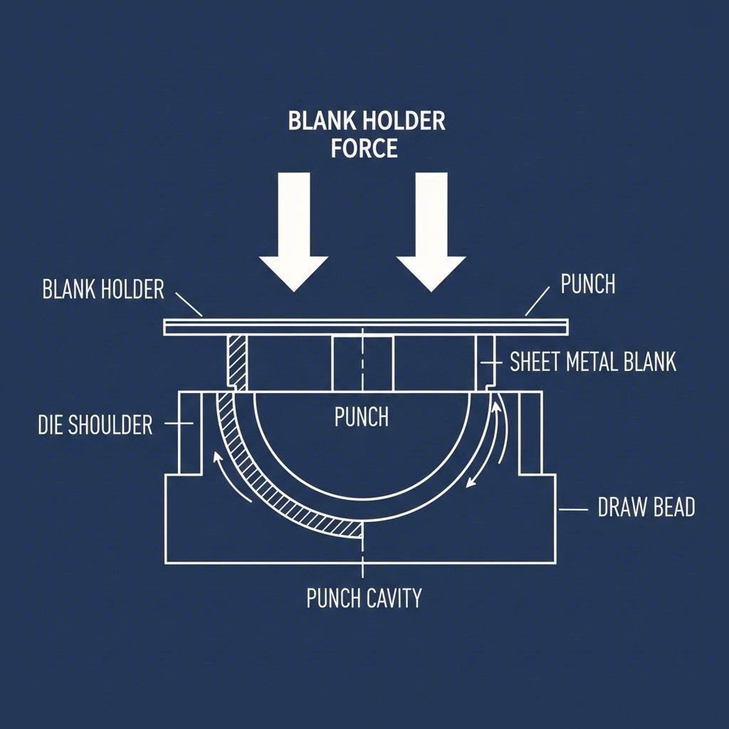
- Forming Defects: These occur during the plastic deformation phase. Examples include splitting (excessive tension causing fracture) and wrinkling (compressive instability causing buckling). These are often governed by the material's flow limits and the blank holder force distribution.
- Dimensional Defects: These are geometric deviations from the CAD model. The most notorious is springback, where the part's elastic recovery changes its shape after being removed from the die. This is the dominant challenge when forming modern High-Strength Steels (HSS) and aluminum panels.
- Cutting and Surface Defects: These are typically tooling-related issues. Burrs result from improper cutting clearance or dull edges, while surface lows, galling, and slug marks are tribological issues caused by friction, lubrication failure, or debris.
Accurate diagnosis prevents the costly mistake of treating a process problem (like wrinkling) with a tooling solution (like re-milling). The following sections analyze the physics behind these defects and outline specific engineering solutions.
Solving Forming Defects: Splits and Wrinkles
Forming defects are often two sides of the same coin: controlling material flow. If the metal flows too easily into the die cavity, it bunches up (wrinkles). If it is restricted too tightly, it stretches beyond its tensile limit (splits).
Eliminating Wrinkles in Deep Drawing
Wrinkling is a compressive instability phenomenon, common in the flange areas of deep-drawn parts like fenders or oil pans. It occurs when the compressive hoop stresses exceed the critical buckling stress of the sheet metal.
Engineering Solutions:
- Optimize Blank Holder Force (BHF): The primary countermeasure is to increase the pressure on the blank holder. This restricts material flow and increases radial tension, smoothing out compressive waves. However, excessive BHF will lead to splitting. Process engineers often use variable binder force profiles that adjust pressure throughout the stroke.
- Utilize Draw Beads: If increasing BHF is insufficient, install or adjust draw beads. These restrict material flow mechanically without requiring excessive tonnage. Square or semi-circular beads can be tuned to provide local flow resistance in specific areas prone to thickening.
- Nitrogen Cylinders: Replace standard coil springs with nitrogen gas springs to ensure consistent, controllable force distribution across the entire die face, preventing local pressure drops that allow wrinkles to form.
Preventing Splitting and Tearing
Splitting occurs when the major strain in the sheet metal exceeds the Forming Limit Diagram (FLD) curve. It is a localized necking failure often found in cup walls or tight radii.
Engineering Solutions:
- Reduce Binder Pressure: Conversely to wrinkling, if the material is restrained too tightly, it cannot flow into the die. Lowering the BHF or reducing draw bead height allows more material to feed into the draw.
- Tribology and Lubrication: High friction coefficients prevent material from sliding over the die radius. verify that the lubricant film strength is adequate for the heat and pressure of the operation. In some cases, applying spot lubrication to specific high-strain areas can solve the issue.
- Radii Optimization: A die radius that is too small concentrates stress. Polishing the die radii or increasing the radius dimension (if part geometry permits) distributes the strain more evenly.
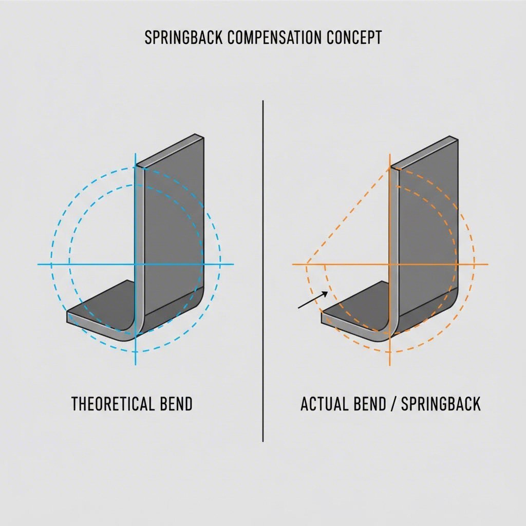
Correcting Dimensional Defects: The Springback Challenge
Springback is the elastic recovery of the material after the forming load is removed. As automotive manufacturers shift toward Advanced High-Strength Steels (AHSS) and aluminum to reduce vehicle weight, springback has become the single most difficult defect to predict and control. Unlike mild steel, AHSS has a higher yield strength and greater elastic recovery potential.
Strategies for Springback Compensation
Solving springback requires a combination of die compensation strategy and process control. It is rarely solved by "hitting it harder."
- Overbending: The die design must account for the springback angle. If a 90-degree bend is required, the tool might need to bend the metal to 92 or 93 degrees so that it springs back to the correct dimension.
- Restriking and Coin-Setting: A secondary operation can be added to "set" the geometry. Restriking the radius compresses the material at the bend, inducing compressive stress that counteracts the elastic tensile recovery.
- Simulation-Driven Compensation: Leading engineering teams now use simulation software like AutoForm or PAM-STAMP to predict springback magnitudes during the design phase. These tools generate a "compensated die face" geometry that is intentionally distorted to produce a geometrically correct final part.
Note on Material Variability: Even with a perfect die, variations in coil mechanical properties (yield strength variability) can cause inconsistent springback. High-volume manufacturers often implement inline monitoring systems to adjust press parameters dynamically based on batch properties.
Eliminating Cutting and Surface Defects
While forming defects are complex physics problems, cutting and surface defects are often maintenance and discipline issues. They directly impact the cosmetic quality of Class-A surfaces (hoods, doors) and the safety of structural components.
Burr Reduction and Clearance Management
A burr is a raised edge on the metal caused by the punch and die failing to fracture the metal cleanly. Burrs can damage downstream assembly equipment and pose safety risks.
- Optimizing Die Clearance: The gap between the punch and the die is critical. If the clearance is too tight, the secondary shear creates a burr. If it is too loose, the metal rolls over before fracturing. For standard steel, clearance is typically set at 10-15% of the material thickness. For aluminum, this may increase to 12-18%.
- Tooling Maintenance: A dull cutting edge is the most common cause of burrs. Implement a strict sharpening schedule based on stroke count rather than waiting for defect detection.
Surface Imperfections: Galling and Slug Marks
Galling (adhesive wear) occurs when the sheet metal fuses microscopically to the tool steel, tearing away material. This is prevalent in aluminum stamping and can be mitigated by using PVD (Physical Vapor Deposition) or CVD (Chemical Vapor Deposition) coatings like Titanium Carbonitride (TiCN) on the tooling surfaces.
Slug Marks happen when a scrap slug is pulled back up onto the die face (slug pulling) and impressed into the next part. Solutions include using spring-loaded ejector pins in punches, adding "roof-top" shears to the punch face to reduce vacuum, or utilizing vacuum systems to pull slugs down through the die shoe.
Systemic Prevention: Simulation and Partner Selection
Modern automotive stamping is moving away from reactive troubleshooting toward proactive prevention. The cost of a defect increases exponentially the further it moves down the production line—from a few dollars at the press to thousands of dollars if a defective vehicle reaches the market.
The Role of Simulation and Inspection
Advanced stamping facilities now employ predictive simulation tools to visualize defects like surface lows and splits in a virtual environment. "Digital stoning" simulates the process of checking a panel with a stone block to reveal microscopic surface deviations that are invisible to the naked eye but apparent after painting.
Furthermore, Automated Optical Inspection (AOI) systems, such as those from Cognex, use machine vision to inspect 100% of parts inline. These systems can measure hole locations, detect splits, and verify dimensional accuracy without slowing down the press line, ensuring that only conforming parts reach the welding stage.
Bridging Prototype to Production
For automotive programs, the transition from engineering validation to mass production is where many defects originate. Choosing a partner with integrated capabilities is crucial. Shaoyi Metal Technology exemplifies this integrated approach, bridging the gap from rapid prototyping to high-volume manufacturing. By leveraging IATF 16949-certified precision and press capabilities up to 600 tons, they help OEMs validate processes early and scale critical components like control arms and subframes with strict adherence to global standards.
Engineering Zero-Defect Production
Solving automotive metal stamping defects is rarely about finding a single "magic bullet." It requires a systematic engineering approach that balances the physics of material flow, the precision of tooling geometry, and the rigor of process maintenance. Whether mitigating springback in AHSS through compensation strategies or eliminating burrs through precise clearance management, the goal remains the same: stability.
By integrating predictive simulation during the design phase and robust optical inspection during production, manufacturers can move from fighting fires to maintaining process capability. The result is not just a defect-free part, but a predictable, profitable, and scalable manufacturing process.
FAQ
1. What is the most common defect in automotive metal stamping?
While frequency varies by application, springback is currently the most challenging defect due to the widespread adoption of High-Strength Steels (AHSS) for lightweighting. Wrinkling and splitting remain common in complex forming operations, but springback presents the greatest difficulty for dimensional accuracy.
2. How is blank holder force related to wrinkling?
Wrinkling in the flange area is directly caused by insufficient blank holder force (BHF). If the BHF is too low, the sheet metal is not restrained enough to prevent compressive instability (buckling) as it flows into the die. Increasing the BHF suppresses wrinkles but increases the risk of splitting if set too high.
3. What is the difference between galling and scoring?
Galling is a form of adhesive wear where material from the sheet metal transfers and bonds to the tool steel, often causing severe tearing on subsequent parts. Scoring typically refers to scratches caused by abrasive particles or debris (like burrs or slugs) trapped between the sheet and the die surface.
4. How can simulation software prevent stamping defects?
Simulation software (Finite Element Analysis) predicts material behavior before any steel is cut. It allows engineers to visualize thinning, splitting risks, and springback magnitudes in a virtual environment. This enables the modification of die geometry—such as adding draw beads or compensating for springback—during the design phase, significantly reducing physical tryout loops and cost.