 Small batches, high standards. Our rapid prototyping service makes validation faster and easier —

Automotive Heat Shield Stamping: Engineering Alloys & Process Specs
TL;DR
Automotive heat shield stamping is a precision manufacturing process designed to manage vehicle thermal loads using thin-gauge metals, typically 0.3mm to 0.5mm aluminum alloys (1050, 3003) or stainless steel (Grade 321). The production workflow often employs progressive die stamping or transfer press operations, integrating a critical embossing stage prior to forming.
This embossing process—creating patterns like hemispheres or stucco—significantly increases the structural rigidity of thin foils and enhances thermal reflectivity. Engineering success depends on balancing material formability with defect management, specifically controlling wrinkling in crash forming and maintaining tight tolerances (as low as ±0.075mm) to ensure seamless assembly.
Material Selection: Alloys, Tempers, and Thickness
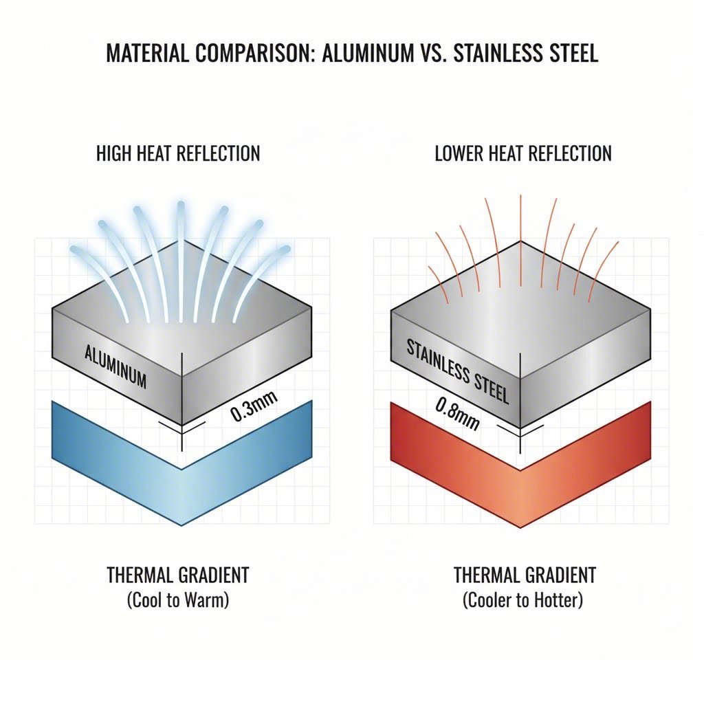
Selecting the correct base material is the foundational step in heat shield engineering, dictated primarily by the component's location and the thermal intensity it must withstand. Manufacturers must balance weight reduction goals with thermal durability, leading to a dichotomy between aluminum and stainless steel applications.
Aluminum Alloys (1000 & 3000 Series)
For general underbody and engine bay shielding, aluminum is the dominant choice due to its high reflectivity and low mass. The industry standard typically revolves around 1050 and 3003 alloys. These materials are often supplied in an O-temper (annealed/soft) condition to maximize formability during the initial stamping stages.
- Thickness Range: Standard shields utilize sheets between 0.3mm and 0.5mm. Double-layer applications may utilize foils as thin as 0.2mm to create air gaps that further insulate against radiant heat.
- Work Hardening: A critical nuance in processing 1050-O aluminum is the physical transformation during embossing. The mechanical action of rolling patterns into the coil work-hardens the material, effectively converting the temper from O to a harder state, often classified as H114. This added stiffness is vital for handling but changes the parameters for subsequent forming operations.
Stainless Steel (Grade 321)
In high-stress thermal zones such as turbochargers and exhaust manifolds, aluminum's melting point (approx. 660°C) is insufficient. Here, engineers turn to 321 Stainless Steel. This titanium-stabilized austenitic stainless steel offers excellent resistance to intergranular corrosion and high-temperature creep.
Case studies, such as those involving turbocharger shields, demonstrate the necessity of stainless steel for components requiring durability under extreme thermal cycling. These parts often demand heavier gauges than their aluminum counterparts and require robust tooling to manage the material's higher tensile strength.
| Material Property | Aluminum 1050/3003 | Stainless Steel 321 |
|---|---|---|
| Typical Thickness | 0.2mm – 0.8mm | 0.3mm – 0.8mm+ |
| Primary Benefit | High Reflectivity, Low Weight | High Heat Resistance, Durability |
| Typical Application | Underbody, Firewall, Fuel Tank | Turbocharger, Exhaust Manifold |
| Forming Characteristic | Excellent (Soft O-Temper) | High Strength (Requires higher tonnage) |
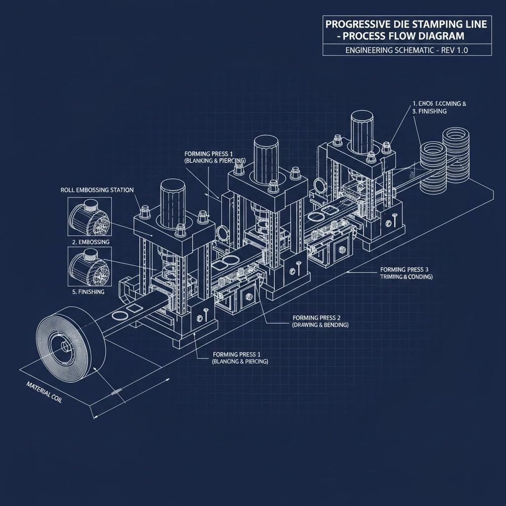
Manufacturing Process: Progressive Die Strategies
The manufacturing workflow for heat shields differs from standard sheet metal stamping due to the fragility of the raw material and the necessity of texturing. The process typically follows a strict sequence: Coil Feeding → Embossing → Blanking → Forming → Trimming/Piercing.
The Emboss-then-Form Sequence
Unlike standard panels where surface finish is preserved, heat shields are intentionally textured. The embossing step usually occurs immediately after the coil is unrolled. This is not merely aesthetic; texturing provides two critical engineering benefits:
- Structural Rigidity: It artificially increases the stiffness of 0.3mm foils, allowing them to hold shape without collapsing.
- Thermal Performance: It increases the surface area for heat dissipation and creates multifaceted reflection angles.
Crash Forming vs. Draw Forming
Engineers must decide between crash forming and draw forming based on budget and geometry.
- Crash Forming: This method uses only a punch and die without a blankholder. It is cost-effective for tooling but prone to uncontrolled material flow. In heat shield production, this often results in wrinkles. However, because heat shields are functional (non-visible) components, industry standards often deem minor wrinkles acceptable as long as they do not interfere with assembly interfaces.
- Draw Forming: For complex geometries where wrinkling causes functional failure, draw forming is employed. This uses a blankholder to control material flow into the die cavity, ensuring a smooth surface but increasing tooling costs.
High-volume production relies on progressive die stamping or automated transfer systems. For example, producing 100,000+ units annually of a stainless steel turbo shield requires substantial press capacity. While lighter aluminum parts may run on smaller lines, robust steel components often demand 200-ton to 600-ton presses to ensure consistent definition and dimensional accuracy.
Manufacturers requiring scalable solutions often look to partners with broad press capabilities. For instance, Shaoyi Metal Technology offers precision stamping with press capacities up to 600 tons, bridging the gap from rapid prototyping to mass production under IATF 16949 standards. Such capacity is essential when transitioning from soft-tool prototypes to hard-tool mass production for complex automotive assemblies.
Engineering Challenges: Defects and Tolerances
Stamping thin-gauge, embossed materials introduces specific defects that process engineers must mitigate.
Managing Wrinkles and Springback
Wrinkling is the most common defect in crash-formed heat shields due to the low stiffness of the sheet and compressive stresses at the flange. While functional wrinkling is often permitted in non-mating areas, uncontrolled folds (overlaps) can lead to cracks or safety hazards during handling.
Springback is another variable, particularly with work-hardened H114 aluminum or high-strength stainless steel. Simulation software is frequently used to predict springback and compensate the die geometry (overbending) to achieve the final shape.
Precision Tolerances
Despite the rough appearance of embossed shields, the attachment points require high precision. A turbocharger shield, for instance, may require tolerances as tight as ±0.075mm on critical diameters to ensure a perfect seal and prevent vibration rattles. Achieving this level of precision requires rigid tooling and often incorporates secondary operations like laser etching for traceability (barcodes, production dates) directly within the production line.
Edge Cracking
Edge cracks can occur during the flanging of embossed sheets. The embossing process reduces the material's ductility, making it more susceptible to tearing when stretched. Optimizing the embossment ratio (height vs. diameter of the bump) is a key design lever to prevent this failure mode.
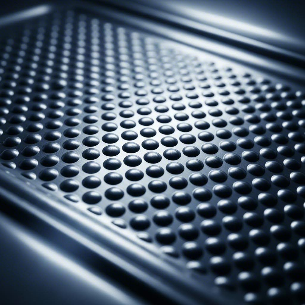
Embossing Patterns and Thermal Function
The texture of a heat shield is a functional specification. The choice of pattern affects both the formability of the metal and its thermal properties.
- Hemispherical Pattern: This is widely used for its balanced multi-directional stiffness and excellent reflectivity. It creates a dimpled effect that is efficient at scattering radiant heat.
- Hexagonal/Stucco Patterns: These provide a different aesthetic and can offer superior durability in environments subject to stone chipping, such as underbody tunnels.
Simulation studies suggest that the geometry of the embossment plays a role in formability. A well-designed pattern allows the material to flow more evenly during the draw, reducing the risk of deep fractures, whereas an aggressive pattern on a brittle alloy will lead to immediate failure.
Applications and Industry Use Cases
Automotive heat shields are deployed wherever thermal management is critical to component longevity and passenger comfort.
- Turbocharger Shields: Typically 321 Stainless Steel. These must withstand rapid thermal cycling and intense radiant heat from the turbine housing.
- Exhaust Manifold Shields: Often multi-layered aluminum or steel. They protect the engine bay wiring and plastic components from the manifold's heat soak.
- Underbody Tunnels: Large, formed aluminum sheets (1050/3003) running the length of the exhaust system. These prevent heat transfer to the cabin floor and often serve a dual purpose of aerodynamic smoothing and noise reduction.
- Electronic Control Unit (ECU) Protection: Smaller, precision-stamped shields designed to deflect heat away from sensitive onboard electronics.