 Small batches, high standards. Our rapid prototyping service makes validation faster and easier —

Key Steps of the Automotive Die Design Process

TL;DR
The automotive die design process is a systematic engineering workflow that transforms a part concept into a robust manufacturing tool. It begins with a thorough part feasibility analysis (DFM), followed by strategic process planning to create a strip layout that optimizes material use. The process then moves to detailed die structure and component design in CAD, virtual simulation for validation and springback compensation, and concludes with the creation of precise manufacturing drawings and a Bill of Materials (BOM) for the toolmaker.
Phase 1: Part Feasibility and Process Planning
The foundation of any successful automotive stamping operation is laid long before any steel is cut. This initial phase, centered on Part Feasibility Analysis and Process Planning, is the most critical stage for preventing costly errors and ensuring an efficient production run. It involves a deep dive into the part's design to determine its suitability for stamping, a practice known as Design for Manufacturability (DFM). This analysis scrutinizes features like sharp corners, deep draws, and material properties to identify potential failure points such as cracking or wrinkling before they become expensive physical problems.
Once a part is deemed manufacturable, the next step is creating a process plan, visually represented by a strip layout. This is the strategic roadmap for how a flat metal coil will be progressively transformed into a finished component. As detailed in a guide by Jeelix, the strip layout meticulously maps out every operation—from piercing and notching to bending and forming—in a logical sequence. The primary goals are to maximize material utilization and ensure the strip remains stable as it travels through the die. An optimized layout can have a significant economic impact; even a 1% improvement in material usage can translate to substantial savings in high-volume automotive production.
During this planning stage, designers mentally deconstruct the final part into a series of stamping actions. For instance, a complex bracket is broken down into its fundamental operations: punching pilot holes, notching edges, executing bends, and finally, cutting the completed part from the strip. This structured thinking ensures that operations are performed in the correct order—for example, piercing holes before bending to avoid distortion.
Key DFM Considerations Checklist:
- Material Properties: Is the selected metal's thickness, hardness, and grain direction suitable for the required forming operations?
- Bend Radii: Are all bend radii generous enough to prevent cracking? An internal radius less than 1.5 times the material thickness is often a red flag.
- Hole Proximity: Are holes located a safe distance from bends and edges to avoid stretching or tearing?
- Complex Geometry: Do any features, like undercuts or side holes, require complex and potentially failure-prone mechanisms like side cams?
- Tolerances: Are the specified tolerances achievable with the stamping process without driving up costs unnecessarily?
Phase 2: Die Structure and Core Component Design
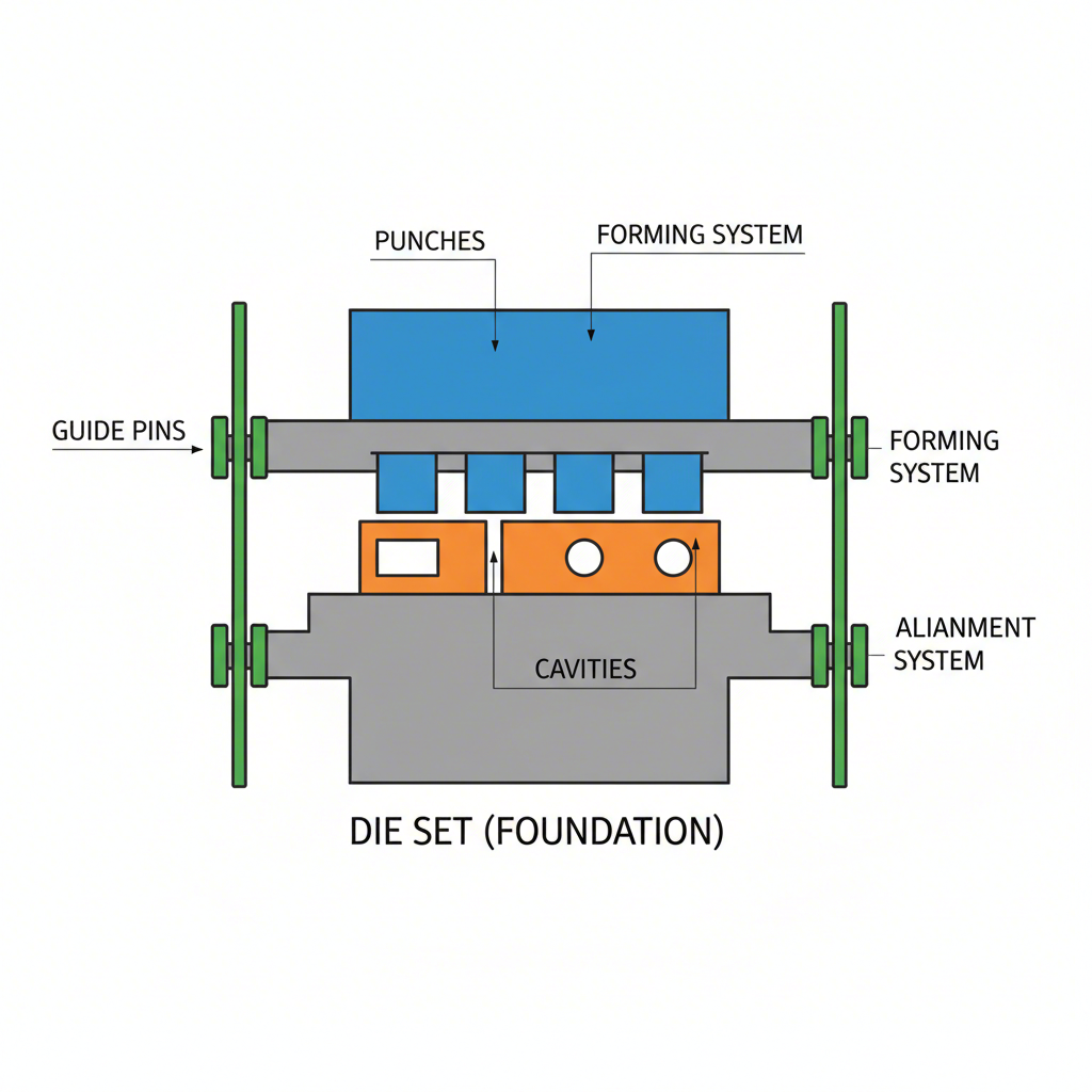
With a solid process plan in place, the focus shifts to designing the physical die—a precision machine composed of multiple interdependent systems. The die's structure serves as the robust framework, or skeleton, that holds all the active components in perfect alignment under immense force. This foundation, often called the die set, consists of upper and lower plates (shoes) precisely aligned by guide pins and bushings. This alignment system is critical for maintaining the micron-level accuracy needed for consistent part quality and preventing catastrophic die collisions during high-speed operation.
The heart of the die is its forming and cutting system, which consists of the punches and die cavities (or buttons) that directly shape the metal. The design of these components is a matter of extreme precision. A critical parameter is the clearance—the small gap between the punch and the die. According to Mekalite, this clearance is typically between 5-10% of the material's thickness. Too little clearance increases cutting force and wear, while too much can tear the metal and leave large burrs. The geometry, material, and heat treatment of these components are meticulously specified to ensure they can withstand millions of cycles.
The choice of material for the die components themselves is a strategic decision that balances cost, wear resistance, and toughness. Different tool steels are used depending on the production volume and the abrasiveness of the part material.
| Die Material | Key Features | Best For |
|---|---|---|
| A2 Tool Steel | Good balance of wear resistance and toughness. Easy to machine. | Medium production runs and general-purpose applications. |
| D2 Tool Steel | High wear resistance due to high carbon and chromium content. | Long production runs and stamping abrasive materials like stainless steel. |
| Tungsten Carbide | Extremely hard and wear-resistant, but more brittle than steel. | Very high-volume production and high-speed stamping operations. |
Phase 3: Virtual Validation and Design Review
In modern automotive die design, the era of costly and time-consuming physical trial-and-error is over. Today, designs are rigorously tested in the digital realm through a process called virtual validation. Using advanced Computer-Aided Engineering (CAE) and Finite Element Analysis (FEA) software, engineers simulate the entire stamping process to predict how the sheet metal will behave under pressure. This virtual tryout identifies potential defects like wrinkling, tearing, or excessive thinning before any physical manufacturing begins, allowing for proactive design corrections.
One of the most significant challenges in stamping, especially with the advanced high-strength steels (AHSS) used in modern vehicles, is springback. This phenomenon occurs when the formed metal partially returns to its original shape after the stamping force is removed. Simulation software can accurately predict the amount and direction of this springback. This allows designers to implement active compensation. For example, as explained by Jeelix, if a simulation predicts a 90-degree bend will spring back to 92 degrees, the die can be designed to over-bend the part to 88 degrees. When the part is released, it springs back to the perfect 90-degree target.
The validation process is a systematic check to ensure the design is robust, efficient, and capable of producing quality parts. It provides a final opportunity for review and refinement before committing to the expensive process of tool building.
The Virtual Validation Process Steps:
- Run Formability Analysis: The simulation software analyzes material flow to check for potential defects like cracks, wrinkles, or insufficient stretching.
- Predict and Compensate for Springback: The degree of springback is calculated, and the forming surfaces of the die design are automatically adjusted to compensate for it.
- Calculate Forces: The simulation calculates the tonnage required for each operation, ensuring the selected press has sufficient capacity and preventing damage to the press or die.
- Conduct Final Design Review: A thorough review of the validated design is conducted by a team of engineers to catch any remaining errors or potential issues before the design is finalized.
Phase 4: Drawing Creation and Manufacturing Handoff
The final stage of the automotive die design process is the translation of the validated 3D digital model into a universal engineering language that toolmakers can use to build the physical die. This involves creating a comprehensive package of technical documentation, including detailed drawings and a Bill of Materials (BOM). This standardized output is essential for ensuring that every component is manufactured to the exact specifications, which is critical for smooth assembly, proper function, and efficient maintenance of the die.
The documentation package serves as the definitive blueprint for the tool's construction. It must be clear, precise, and unambiguous to avoid costly mistakes on the shop floor. This detailed planning is a hallmark of expert manufacturers in the automotive sector. For instance, companies like Shaoyi (Ningbo) Metal Technology Co., Ltd. specialize in turning these precise design packages into high-quality automotive stamping dies and components, leveraging advanced simulations and deep expertise to serve OEMs and Tier 1 suppliers with exceptional efficiency and quality.
The final design package contains several key elements, each serving a specific purpose in the manufacturing and assembly workflow. The quality and completeness of this documentation directly impact the final tool's performance and longevity.
Key Elements of a Final Design Package:
- Assembly Drawing: This master drawing shows how all the individual components fit together in the final die assembly. It includes overall dimensions, shut height, and details for mounting the die in the press.
- Detail Drawings: A separate, highly detailed drawing is created for every custom component that needs to be machined. These drawings specify exact dimensions, geometric tolerances, material type, required heat treatment, and surface finish.
- Bill of Materials (BOM): The BOM is a comprehensive list of every single part required to build the die. This includes both the custom-machined components and all standard off-the-shelf parts like screws, springs, guide pins, and bushings, often with supplier part numbers.