 Small batches, high standards. Our rapid prototyping service makes validation faster and easier —

The Complete Guide to Automotive Dies
Section 1: Definition and Classification of Automotive Dies
1. Definition of Dies
A die is an industrial product designed with a specific structure to shape materials through a particular method. It also serves as a production tool for manufacturing automotive metal components in batches, ensuring these parts meet precise shape and dimensional requirements.
From large components like car doors, engine hoods, and trunk lids to smaller ones such as chassis vibration dampers, engine brackets, rear sub frames, and shock absorber sleeves, all these automotive parts rely on stamping dies for their formation.
The metal components produced using dies possess a level of precision, consistency, and production efficiency that cannot be matched by other processing methods. Dies play a crucial role in determining product quality, cost effectiveness, and the ability to develop new products. This is why dies are proudly referred to as the "Mother of Industry."
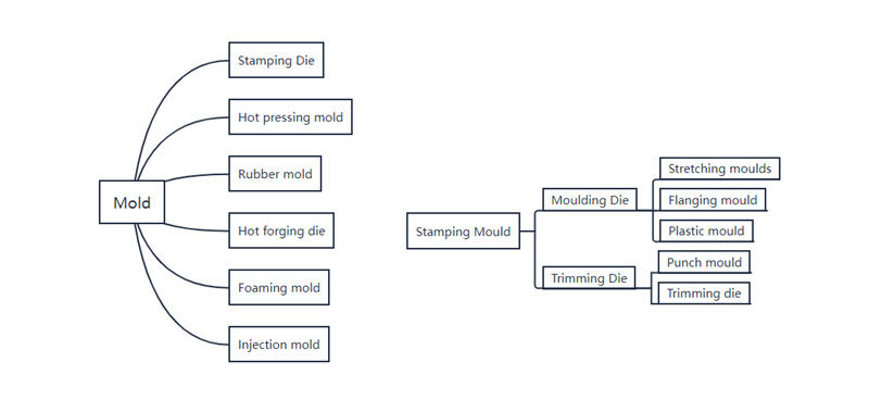
Section 2: The Forming Characteristics of Automobile Stamping Dies
1. Definition of Automobile Stamping Dies
Automobile stamping dies refer to the molds used to manufacture automotive parts through stamping processes. In this process, metal sheets (steel or aluminum alloys) or non metallic materials (such as fiberglass or carbon fiber sheets) are placed in the die cavity. Then, a press machine applies pressure to the material through the dies. This causes the material to separate or deform plastically, resulting in parts with the desired shape and size. These production molds are called automobile stamping dies.
2. The Forming Characteristics of Various Types of Stamping Dies
One common type of stamping die is used for deep drawing operations. This die transforms flat sheet metal into components with considerable depth, such as oil pan bottoms or inner door panels. The process involves placing a flat sheet metal blank into the die and then drawing it into a three dimensional shape using the press. For example, a flat steel sheet can be drawn into a bowl or box like shape. This type of die is widely used in the automotive industry for manufacturing parts with complex shapes and depth requirements.
Trimming Dies: Trimming dies are used to remove excess material from formed parts, resulting in a cleaner and more neat appearance. They are typically employed after drawing or forming operations to ensure precise dimensions.
Piercing Dies: Piercing dies create holes in materials, similar to using a paper punch but on sheet metal to produce round, square, and other shaped holes. They are widely used for components such as frames and brackets.
Piercing Dies: Piercing dies create holes in materials, similar to using a paper punch but on sheet metal to produce round, square, and other shaped holes. They are widely used for components such as frames and brackets.
Flanging Dies: Flanging dies form raised edges around holes via a stretching process. This process is generally used to increase strength or facilitate subsequent welding or linking. Flanging dies are commonly used in body in white assemblies to enhance weldability or to strengthen component edges.
Restriking Dies: Restriking dies perform a "secondary correction" on formed parts to achieve greater shape accuracy. For instance, if you fold a paper box but the edges aren't sharp enough, a reshaping die can further "press" it to make it more square and smooth. These dies are primarily used to enhance the appearance and dimensional accuracy of components, especially for visible parts.
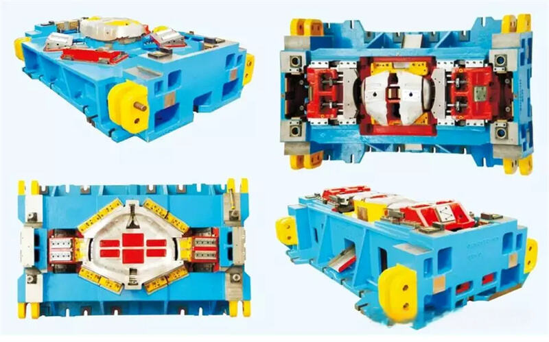
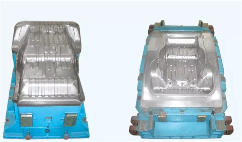
Section 3: The Structure of Stamping Dies
According to the function and requirements of each part, stamping dies are mainly composed of two categories: process parts and structural parts.
- Process Parts
1. Punch and die parts: Parts that come into direct contact with materials during stamping processes, such as punch parts (punches, etc.) and die parts (concave dies, etc.), as well as punch and die seats (punch seats, die seats, etc.), and punch and die holders (punch holders, die holders, etc.).
- Structural parts
Parts that serve to assemble, fit, and guide in molds, such as upper and lower die seats (upper die seats, lower die seats, etc.), die spacers (die pads, etc.), guide parts (guide pins, bushings, etc.), and positioning parts (positioning pins, etc.).
Generally speaking, the main structural components of automotive molds include the following:
Upper die seat, lower die seat, punch, die, concave die, die holder, positioning stop, ejector mechanism, limit device, upper and lower templates, punch and die fixing plate, guide pin, bushing, guide post, etc., as well as safety devices, coolant holes, and other special structures.

Chapter 2: Manufacturing Knowledge of Automobile Moulds
Section 1: Characteristics of Automobile Mould Manufacturing
1. High manufacturing quality requirements
Mould manufacturing requires not only high machining accuracy but also good machining surface quality. Generally, the manufacturing tolerances of the working parts of moulds should be controlled within ±0.01 mm, with some even requiring micrometrelevel ranges. The surface of the mould after machining must be free of any defects, and the surface roughness Ra of the working parts must be less than 0.4 μm.
2. Complex shapes
The working parts of moulds are usually complex twodimensional or threedimensional curved surfaces, rather than simple geometric shapes used in general mechanical processing.
3. High material hardness
Moulds are essentially a type of mechanical processing tool with high hardness requirements. They are typically made of materials such as quenched tool steel. Traditional mechanical processing methods are often very difficult to use for such materials.
4. Singlepiece production
Usually, the production of a small number of stamping parts requires 3 5 moulds. Mould manufacturing is generally singlepiece production. The manufacture of each mould must start from the design and may take more than a month or even several months to complete. Both the design and manufacturing cycles are relatively long.
Section 2: Manufacturing Process of Automobile Moulds
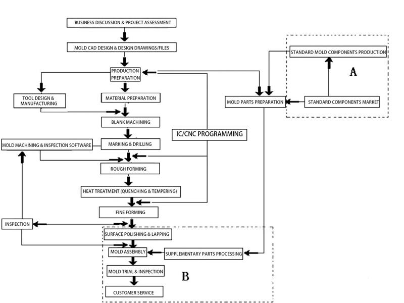
Stamping Process Analysis and Die Production Estimation
When accepting a die manufacturing assignment, first conduct a stamping process analysis based on the product part drawings or physical samples. Determine the number of dies, their structure, and the main machining methods. Then perform a die estimation.
1. Stamping Process Analysis
Stamping is a machining method that uses dies to apply external force to blanks, causing plastic deformation or separation to obtain workpieces with specific dimensions, shapes, and properties. The application of stamping processes is very extensive, as it can process metal sheets and bars as well as various nonmetallic materials. Since processing is usually carried out at room temperature, it is also known as cold stamping. Stamping process analysis is conducted to comprehensively determine the optimal stamping process based on various parameters.
The quality of stamping part process directly affects the product's quality and cost. A stamping part with good process requires a simple sequence of operations, is easy to process, can save raw materials, extend die life, and ensures stable product quality.
Under certain production batch conditions, highquality, lowcost parts can be manufactured to achieve good production efficiency. When considering the process of stamping parts, the following principles are generally followed:
(1) Simplify production procedures as much as possible, using the fewest and simplest stamping operations to complete the entire part processing and improve labor productivity.
(2) Ensure the stability of product quality and reduce the scrap rate.
(3) Simplify die structure as much as possible and extend die life.
(4) Improve the utilization rate of metal materials and try to reduce the variety and specifications of materials used.
(5) Ensure product versatility and interchangeability.
(6) Part design should facilitate stamping operations and support production mechanization and automation.
2. Mould Estimation:
(1) Mould Cost
This refers to material costs, purchased parts costs, design costs, processing costs, assembly and testing costs, etc. Where necessary, it also involves estimating the cost of tools and processing methods used in various manufacturing processes, ultimately determining the mould manufacturing cost.
(2) Delivery Time
This involves estimating the time required to complete each task and determining the delivery schedule.
(3) Total Mould Life
This refers to estimating the single use life of a mould and its total service life after multiple minor repairs (that is, the natural lifespan of the mould in the absence of accidents).
(4) Product Material
This refers to the performance, size, consumption, and utilization rate of the materials specified for the product.
(5) Equipment Applied
Know about performance, specifications and ancillary equipment of the equipment applied for the mould.
II. Mould Design
When conducting mould design, it is essential to collect as much information as possible, study it carefully, and then proceed with the design. Failure to do so means that even if the designed mould has excellent functionality and high precision, it may not meet requirements and the completed design may not be optimal. The information to be collected includes:
1. Information from the business aspect is the most crucial, including:
①Production volume (monthly and total production, etc.);
②Unit price of the product;
③Mould price and delivery time;
④Properties of the material to be processed and supply methods, etc.;
⑤Future market changes, etc.;
2. Quality requirements, purpose of the product to be processed, and the possibility of design modifications, shape changes, and tolerances;
3. Information from the production department, including equipment performance, specifications, operation methods, and technical conditions for using the mould;
4. Information from the mould manufacturing department, including processing equipment and technical levels, etc.;
- Supply conditions of standard parts and other purchased components, etc.
III. Mould Drawing
(1) Assembly Drawing
Once the mould design and structure are finalized, an assembly drawing can be created. There are three methods for drawing assembly drawings:
① The front view is drawn to show the upper and lower moulds in a closed state (at the lower dead point), and the top view only shows the lower mould.
② The front view shows the upper and lower moulds combined, with the top view showing half of each.
③ After drawing the combined front view, separate top views of the upper and lower moulds are created. Choose the method that best suits the mould structure.
(2) Detail Drawings
Detail drawings, based on the assembly drawing, must satisfy all fitting relationships and include dimensional tolerances and surface roughness. Some may need technical conditions. Standard parts don't need detail drawings.
IV. Process Planning and Requirements for Mould Manufacturing
(1) Review the mould and its components: including names, drawings, drawing numbers or company product codes, technical conditions, and requirements.
(2) Select and determine the blanks for all mould components: including blank type, material, supply condition, dimensions, and technical requirements.
(3) Establish process references for mould production, aiming to unify them with design references.
(4) Design and plan the manufacturing process for mould forming components:
① Analyze the structural elements and machinability of forming components;
② Determine the machining methods and sequence;
③ Select machine tools and fixtures.
(5) Design and plan the assembly and trial mould processes:
① Determine the assembly reference;
② Determine the assembly methods and sequence;
③ Inspect standard parts and perform additional machining if needed;
④ Conduct assembly and trial moulding;
⑤ Perform inspection and acceptance.
(6) Determine machining allowances:Each process based on technical requirements and relevant factors, using table lookup with corrections or experiencebased estimation.
(7) Calculate and set process dimensions and tolerances:(upper and lower deviations) for mould forming components using calculation, table lookup, or experiencebased methods.
(8) Select machine tools and fixtures for the processes.
(9) Calculate and set cutting parameters: (spindle speed, cutting speed, feed rate, depth of cut, and feed passes) to ensure machining quality, improve efficiency, and reduce tool wear.
- Calculate and set manhour quotas to specify the mould manufacturing cycle and time per process: This is crucial for boosting staff motivation, enhancing technical skills, and meeting contract deadlines.
V. NC, CNC Programming
Programming Steps:
(1) Workpiece Design
Leverage the high automation of CNC machines to minimize manual intervention. Ensure uniform chip removal during machining to reduce machine vibration and extend its service life.
(2) Determination of Machining Methods
Shaoyi’s engineers analyze the geometry, machinability, material properties, and technical requirements of the part. They then define the optimal process route, machine selection, and machining steps.
(3) Tool Selection
Choose cost effective, efficient tools based on workpiece size, part dimensions, material properties, quality requirements, and tool inventory. Input tool parameters into the UG program for calculation and note tools on the program sheet.
(4) Workstep Division
Break down the process plan into specific worksteps and define the tasks of each.
(5) Machining Path Determination
Define the machining scope and sequence to determine the machining path.
(6) Dimensional Tolerance Design
Design dimensional tolerances based on part quality requirements.
(7) Cutting Parameter Selection
Design or select fixtures and tools. Define machining characteristics (e.g., tool setting point, tool path, speed, depth, step over, spindle speed). Select coolants.
(8) Positioning Datum and Fixture Selection
For parts with special positioning needs, design a positioning datum and customize fixtures.
(9) Information Generation
Generate CNC tool path programs, including data preparation, program creation, and debugging. Record the processing information as per the transmission medium.
(10) Trial Cutting
Conduct trial machining and verify the trial parts. Modify programs and adjust parameters as needed until requirements are met.
(11) Production Machining
Officially machine production parts using the approved trial program.
VI. Part Machining
(1) The machining workshop processes large parts per drawings, processes, and technical requirements.
(2) The assembly workshop machines small parts according to drawings and process requirements.
(3) The assembly workshop marks, drills, and assembles inserts onto the base plate (fixture) as per drawings and process requirements, then secures and sends them to the machining workshop.
(4) The machining workshop performs rough (or semi finish) machining of part features like form, contour, holes, and edges as per drawings, processes, and technical requirements.
(5) The fitting and adjustment workshop trims, disassembles, marks, and drills parts as per drawings, processes, and requirements.
(6) The assembly workshop re machines small parts (like hollow and back cut parts) as per drawings, processes, and technical requirements.
(7) The machining workshop finish machines part features like form and contour (for draw dies only) as per drawings, processes, and technical requirements.
(8) After re machining, the fitting and adjustment workshop checks for unprocessed or non compliant areas. If parts are fully machined and compliant, they’re sent for heat treatment.
(9) Heat Treatment
Per process requirements, parts undergo overall or surface heat treatment (including quenching, annealing, normalizing, tempering, blackening, bluing, carburizing, nitriding, salt bath, aging, and flame hardening). This achieves the required HRC value for mold.
(10) The fitting and adjustment workshop sends heat treated parts with drawings to the assembly workshop for finish machining.
(11) The assembly workshop finish machines parts (via surface grinding, cylindrical grinding, or electrical discharge machining) as per drawings, processes, and technical requirements.
(12) The fitting and adjustment workshop re assembles inserts onto the base plate (fixture), secures them, and sends them to the machining workshop as per drawings, processes, and technical requirements.
(13) The machining workshop finish machines parts (form, holes, edges, etc.) as per drawings, processes, and technical requirements, then sends them to the fitting and adjustment workshop.
(14) The fitting and adjustment workshop trims features and installs accessories as per drawings, processes, and technical requirements until parts meet drawing standards, completing die assembly.
(15) The fitting and adjustment workshop cleans moulds, applies anti rust oil and paint, and attaches nameplates as per drawings, processes, and technical requirements, finishing all pre shipment and mould perfection tasks.
(16) Assembly is combining machined parts into a complete mould. Besides mere part tightening or dowel pin insertion, minor hand trimming or machining usually occurs during assembly adjustment.
(17) The fitting and adjustment workshop debugs and trims moulds until qualified process parts emerge. This includes pre acceptance, mould modification, and final client approval.
- The fitting and adjustment workshop completes final cleaning, anti rust treatment, painting, and nameplate attachment, finishing all pre shipment and mould perfection tasks.
VII. Mould Adjustment
After stamping mould manufacturing, dynamic precision verification via trial stamping on a press is essential. This trial stamping inspection of process parts assesses mould manufacturing quality, identifies issues, eliminates defects, and ensures compliance with part quality standards. This process, known as manufacturing adjustment, is typically carried out by the manufacturing unit using its trial stamping equipment.
Once the mould is handed over to the using unit, the press on the production line often differs from that of the manufacturing unit, as do the environment and conditions. Therefore, after mould transfer, a trial stamping acceptance must be conducted. During this process, the mould is once again inspected under trial stamping conditions to identify and resolve any manufacturing related issues, ensuring the production of qualified stamped products. This process is referred to as operational adjustment.
Manufacturing and operational adjustments are two key aspects of stamping mould trial stamping adjustments, collectively known as stamping mould adjustment. This process helps identify issues in stamping part manufacturability, stamping process design, stamping mould design, and stamping mould manufacturing. It also enables the accumulation of extensive raw data and valuable practical experience.
Section 3 Common Issues in Mould Manufacturing and Usage
1. Impact of Mould Surface Quality on Service Performance
(1) High Ra values on punch and die working surfaces increase initial die hole wear and enlarge punchdie gaps.
(2) Increased Ra values on guide sleeve surfaces disrupt oil films, causing friction, while overly low Ra values may lead to “seizing”, accelerating surface damage.
(3) High Ra values lower fatigue strength. For instance, punch surfaces with high Ra values are prone to stress concentration and crack formation under alternating loads, causing fatigue damage.
(4) High Ra values reduce corrosion resistance. Corrosive media accumulate in surface valleys, causing chemical corrosion, while peaks are susceptible to electrochemical corrosion.
2. Causes of Mould Cracking
(1) Poor mould material quality makes it prone to fragmentation during processing.
(2) Improper quenching and tempering can cause deformation.
(3) Insufficient mould grinding flatness results in flexural deformation.
(4) Insufficient mould strength, narrow cutting edge spacing, and irrational structure (e.g., lack of spacer plates) are design related issues.
(5) Wire EDM machining was done improperly.
(6) Press selection is unsuitable with insufficient tonnage and cutting force, or the die was set too deep.
(7) Inefficient material removal due to no demagnetization before production or blockages from broken needles or springs during production.
3. Factors Affecting Mould Life
(1) Stamping equipment.
(2) Mould design.
(3) Stamping process.
(4) Mould material.
(5) Hot working process.
(6) Machined surface quality.
(7) Surface strengthening treatment.
- Proper use and maintenance.
Section 4 Stamping Part Production for Automobile Moulds
auto stamping parts moulds is basically divided into two categories: separation and forming processes, which depend on the part's shape, size, accuracy, material, and production volume.
1. Separation Processes
These processes involve applying stress to metal sheets beyond the material's strength limit to cause shear fracture and separation. They mainly include:
① Blanking: Using a die to cut along a closed contour curve to separate parts from the blank, with the cut down part being the desired piece.
② Punching: Using a die to cut along a closed contour curve to separate parts from the blank, where the cut down part is waste material and the remaining is the desired piece.
③ Shearing: Using shears or a die to cut parts along an open contour curve; or partially cutting the workpiece without complete separation.
④ Trimming: Trimming the edges of formed parts to make them neat or shape them as required.
2. Forming Processes
These processes involve applying stress to metal sheets beyond the material's yield limit to cause plastic deformation and form the desired shape. They mainly include:
① Bending: Using a die to bend the blank into the required shape.
② Drawing: Forming flat blanks into various hollow parts, which can be either constant thickness or thinning drawing.
③ Flanging: Forming a flange around the edge of a hole or sheet to enhance strength or facilitate assembly.
④ Bulging: Using pressure to expand a small diameter hollow part, tube, or sheet into a larger diameter curved shape from the inside out.
⑤ Expansion and Necking: Forming methods to increase or decrease the radial size of a hollow or tubular blank in a specific area.
⑥ Calibration: An auxiliary forming process to correct geometric defects in sheet metal parts after various forming processes or distortion from heat treatment, ensuring the part meets design requirements for shape and size accuracy.
Chapter 3: Basic Knowledge of Automobile Mould Adjustment
Section 1: Scope of Work for Mould Adjusters
Mould adjustment involves using hand tools, drilling machines, and specialized mould making equipment. Through technical processes, it completes tasks that mechanical machining can't handle. It also assembles and debugs machined parts into qualified mould products per the mould assembly drawing.
To manufacture high quality moulds, mould adjusters must:
(1) Be familiar with mould structure and principles;
(2) Understand technical requirements and manufacturing processes of mould parts and standard components;
(3) Master machining and assembly methods for mould parts;
(4) Be knowledgeable about the use of forming machines and mould installation;
(5) Know how to debug moulds;
(6) Be skilled in mould maintenance, care, and repair.
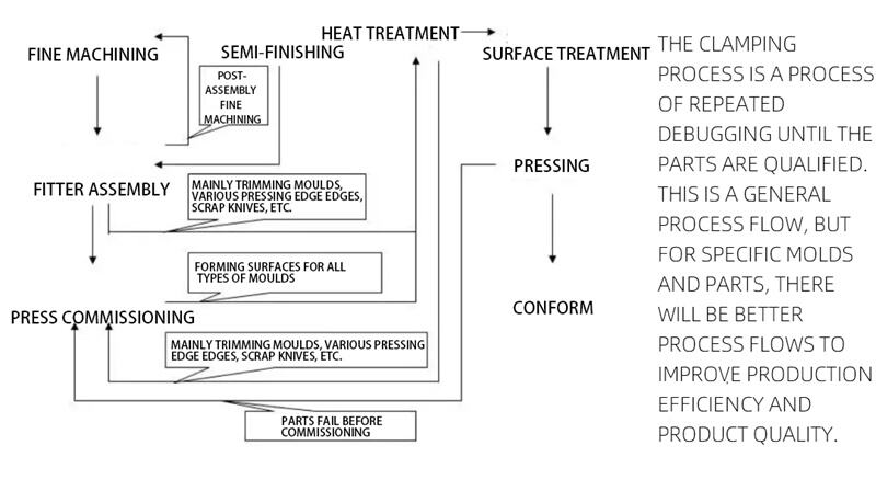
Section 2: Mould Adjustment Process
Section 3: Skills Required for Mould Adjusters
1. Drawing Reading Ability
Drawing reading is fundamental for mould fitters. It primarily involves understanding part drawings and assembly drawings. Part drawings mainly reflect the dimensions of machined surfaces, relative positions, form tolerances, and machining accuracy. Assembly drawings mainly show the relative positions and fitting tolerances between parts. Mould assembly, in actual practice, differs significantly from general assembly as per assembly drawings.
2. Drilling Processing
Drilling is required for fixing or positioning mould standard parts, inserts, wedges, etc. Key aspects of drilling include:
Correct use of drilling machines.
Drill bit grinding and the effect of cutting edge angles on machining.
Proper workpiece clamping.
Influence of different materials on spindle speed, feed rate, and cutting edge angles, and selection of cutting fluids.
Selection of standard thread hole diameters and correct use of taps.
Maintenance and safety precautions for drilling machines.
3. Grinding Processing
Use of pneumatic or electric tools to grind mould surfaces.
4. Measuring Tools
Measuring tools are used to measure actual dimensions of objects or between objects. Common tools include tape measures, steel rulers, feeler gauges, vernier calipers, micrometers, internal diameter dial indicators, and R gauges. The figures in parentheses represent the accuracy of the measuring tools.
5. Assembly
Assembly is a crucial part of mould adjustment. Mould assembly differs from general fitting assembly. General fitting assembly is typically static, following assembly drawings. In contrast, mould assembly is mostly dynamic, considering press working conditions and deformation after heat treatment. Common types include:
Installation of mould base guide plates: Ensure tight contact of guide plates against the reference surface, find relative positions, mark hole centers, drill, and tap. Check the fit rate between guide plates and installation surfaces. After installation, check the clearance between upper and lower mould base guide plates (≤10 µm for outer guides, ≤8 µm for inner guides).
Installation of lifters and wedges: Divided into three parts: installation slot, sliding part, and driving seat. The installation slot is the reference. The sliding part is based on the installation slot, and the driving seat is based on the sliding part. For punch positioning in punch and die moulds with lifters (wedges), use CNC for preliminary positioning and adjust side clearances on the press.
Effective contact between guide plates and installation surfaces should be over 80%. Side clearance of guide plates: ≤3 µm (below 500), ≤5 µm (above 500). Upper guide plate clearance: ≤2 µm (below 500), ≤3 µm (above 500). Ensure smooth movement.
Installation of trim die inserts: Assemble and rough machine after hardening. Adjust form and cavity, including form and clearance. Use reference surfaces or diagonal positions for positioning. Finish machine after adjustment.
Positioning of punch and die in piercing dies: Due to small side clearances (only 3 µm), manual positioning on the press is often required. For cylindrical punches, find one point on CNC; for non cylindrical punches, find two points for preliminary positioning. For precise positioning, apply oil clay to the punch and red lead to the die, then use dowel pins after press testing.
Assembly of scrap knives: Similar to punch assembly. As scrap knives may change significantly after trim die form and cavity adjustment, manual positioning is common. Place the mould on the press, align the scrap knife with the cavity, scribe to find the position, drill, tap, and finalize positioning. Items (4) and (5) utilize a 1.5 µm allowance between screws and holes.
6. Adjustment
Adjustment is a key process to ensure moulds produce qualified parts, enhance performance and life, and provide accurate parameters for debugging. It often overlaps with assembly. Before adjustment, understand mould type, structure, part shape, and reference benchmarks. Adjustment includes static (fitting rate, surface roughness) and dynamic adjustments (clearances of guides, bushings, plates; fitting rates of guides, wedges with installation and reference surfaces; clearances between trim die cavities and pressure rings; clearances between inserts; travel of all moving parts; press pressure; adjustments of inserts, scrap knives; fillets of draw die transition surfaces; and blank holding force). Factors affecting moulds include:
A、Fitting rate: Poor fitting in draw or forming dies causes uneven part thickness, tearing, wrinkling, or inaccurate sizes. Poor fitting in trim, forming, or piercing dies leads to part misalignment, scuffs, or tears.
B、Surface roughness: Causes part surface scratches. High roughness in draw dies increases drawing resistance, causing part scuffs or tears. Surface roughness of draw die inserts, drawing ribs, and transition corners should reach 0.8 or higher.
C、Clearances between standard parts: Excessive clearance causes surface scuffs; insufficient clearance leads to misalignment and reduces mould life.
D、Draw die pressure: Excessive pressure causes part tearing or thinning; insufficient pressure causes wrinkling. For double action presses, excessive outer pressure may prevent operation. Many factors affect part quality; causes must be analyzed comprehensively and excluded individually, relying on experience. When adjusting fitting rates, use the punch as the reference. Only deburr and improve surface roughness; no grinding or form changes allowed.
7. Press Usage
Moulds use hydraulic or mechanical presses. Hydraulic presses are generally for draw dies; mechanical presses for other dies. When placing a mould on a press, note the movement of the pressure ring. Avoid excessive downward adjustment to prevent mould damage. For mechanical presses, use locating blocks and oil clay for positioning and checking. For draw dies, set initial pressure per design, then adjust incrementally. Before placing the mould on the press, check mould cleanliness, screw tightness, completeness of parts to be debugged, and proper press function.
8. Safety Precautions
Fitting is a special occupation with various safety risks. Adhere to the principle of "safety first, prevention foremost". Hazards include drilling machines, cranes, grinders, presses, noise, and slippery floors. Avoid harming others, being harmed, or self harm. Stay alert and enhance safety awareness and skills.
9. Common Part Defects
Main defects include tearing, wrinkling, scuffing, localized thinning, deformation, and burrs. Causes are numerous, such as design rationality, process appropriateness, material strength, mould surface roughness, fillet radii, fitting rate, flatness, and precision of moving clearances.