 Small batches, high standards. Our rapid prototyping service makes validation faster and easier —

Stamping Die Design Process Analysis, Worth Collecting!
Part One: Introduction to CAE
Application of CAE in Stamping:
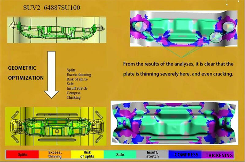
Compared with general stamping parts, automotive body parts are characterized by thin materials, complex shapes, large sizes, and multi - curved surfaces. The traditional "cut - and - try" approach would delay new product development due to repeated trials and die repairs, putting companies at a competitive disadvantage.
In recent years, computer applications and the finite element method have driven the development of sheet metal forming CAE in the automotive industry. Designers can predict metal flow, stress - strain, temperature distribution, die stress, and potential forming defects like wrinkles and cracks. They can determine the stamping process and parameters, and optimize die designs. Each simulation acts like a trial process, reducing trial times. Mature simulation technology can achieve qualified die and process designs on the first attempt, avoiding die repairs, shortening product development cycles, enhancing product quality, and boosting competitiveness.
Overview of Sheet Metal Forming CAE Software:
Leading automotive companies globally emphasize sheet metal stamping simulation. Almost all automotive body part development processes involve simulation analysis. Major sheet metal forming simulation software includes DYNAFORM, AUTOFORM, and PAM - STAMP.
CAE Simulation Objectives:
1. Improve formability and ensure die - trying and production stability.
2. Optimize design with diverse materials and processes.
3. Shorten die process design cycle.
4. Reduce die - trying times and machining workload.
5. Use low - tonnage stamping machines and smaller blanks.
6. Lower die costs.
Aim: Complete die development and debugging with high quality and on time, within a controllable cost range!
Part Two: Introduction to Stamping Processes and Dies for Automobiles
1. Cold Stamping
Cold stamping refers to the process of applying pressure to materials through dies installed on a press machine at room temperature. This causes the materials to separate or undergo plastic deformation, resulting in the desired parts. It is a metalworking process.
2. Characteristics of Cold Stamping:
The product size is stable, with high precision, light weight, good stiffness, and excellent interchangeability. Additionally, cold stamping is highly efficient, has low energy consumption, and is easy to operate. It can also be automated with relative ease.
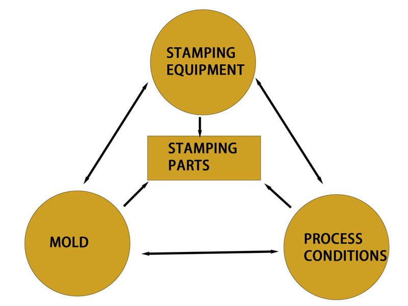
Factors affecting stamping parts
Basic Stamping Process Classification:
Cold stamping can be divided into two main categories: cutting process and forming process.
1. The cutting process separates the sheet metal along a certain contour line to obtain a stamped part with a certain shape, size and section quality.
2. The forming process causes the blank to deform plastically without tearing to obtain a stamped part with a certain shape and size.
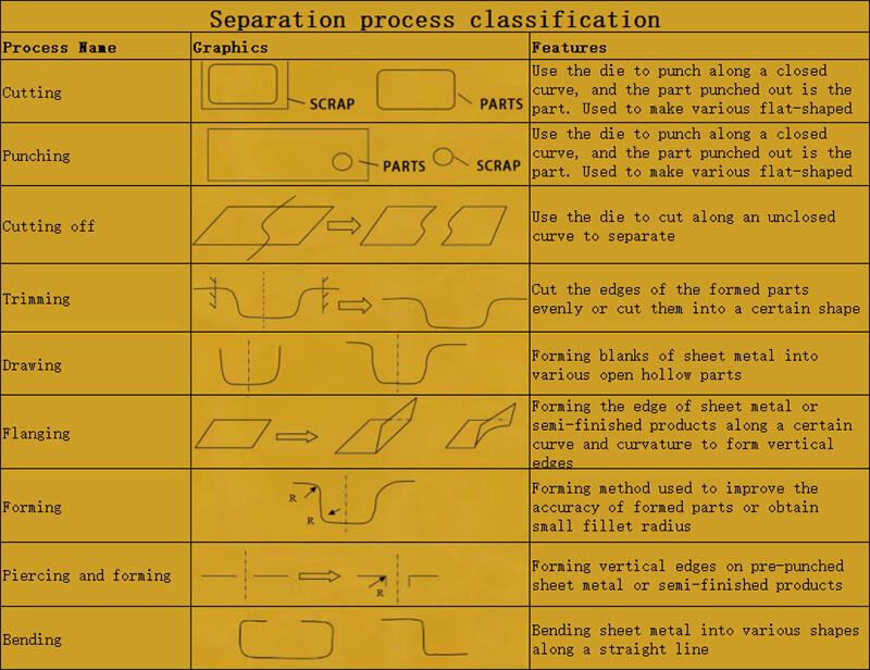
Separation process classification
Differences between drawing and forming:
1.When the part forming depth exceeds 10MM, it is best to use the drawing method to avoid the phenomenon of metal flow. If it is less than 10MM, forming can be considered. At the same time, to avoid material overlap during the forming process, process defects are usually added.
2. Drawing requires complete process compensation surfaces and pressing surfaces, forming a closed geometric shape. Forming only requires local action and doesn't need to be fully closed.
3. For the same part and material grade, products from drawing processes are more rigid than those from forming processes.
4. Drawing is suitable for near-closed parts, while forming is better for open parts.
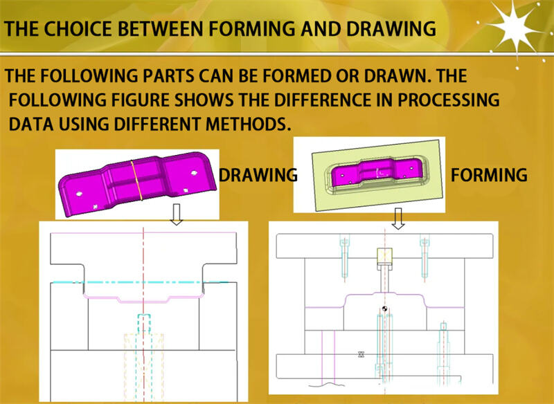
THE CHOICE BETWEEN FORMING AND DRAWING!
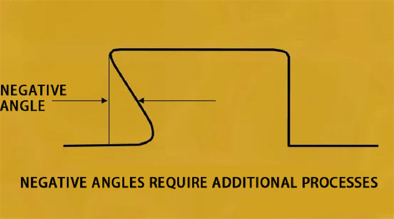
Key Points for Drawing
1. Ensure that the punch can fully contact the part that needs to be stretched, that is, there is no negative angle.
2. At the beginning of stretching, the contact state between the punch and the blank should be good.
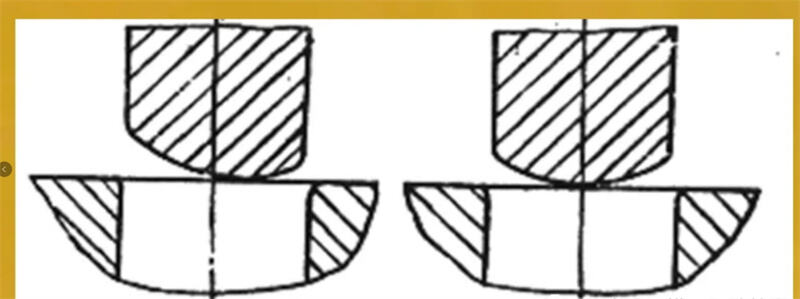
1. The contact area should be as large as possible and close to the center: (as shown in Figure 1-2)
2. The points on the punch surface that contact the blank at the same time should be as many and dispersed as possible; (as shown in Figure 1-2)
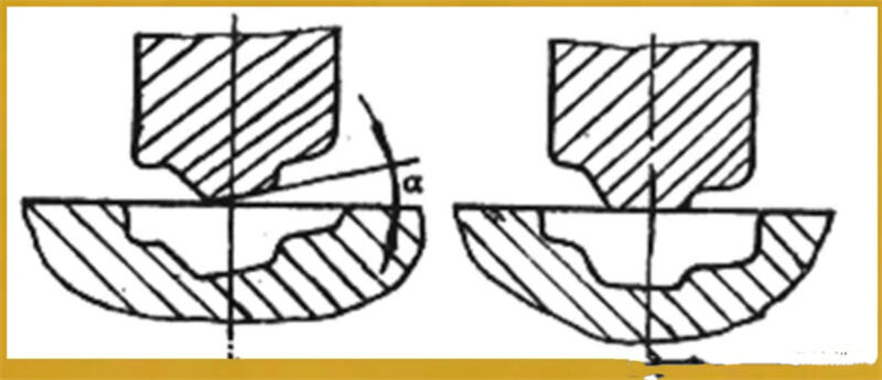
3. The size of the inclusion angle on both sides of the punch should be as close as possible: 8 (as shown in Figure 1-3)
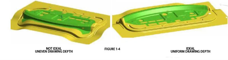
4. The stretching depth of each part should be as uniform as possible. (as shown in Figure 1-4)
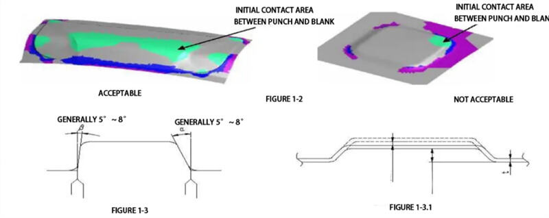
As shown in Figure 1-3, the difference between angles α and β is large, causing uneven material flow in various areas.
Wrap angle (or Draw angle): Improper angles can lead to the following drawbacks:
- If too large, it will lead to insufficient plastic deformation of the part, making the part prone to springback and distortion, and resulting in low material utilization.
- If too small, it will cause difficulty in material feeding, making it prone to fracture, and resulting in insufficient plastic deformation in the middle part of the component.
3. Forming treatment of shallow concave-convex features on the part surface See Figure 1-3. 1
For features with a height less than 0. 5mm on the part surface, it is necessary to deepen them by 0. 2mm during drawing or forming, and subsequent processes will be carried out according to the original die dimensions.
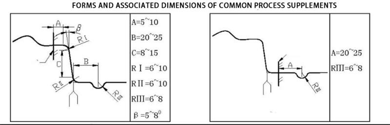
Process Addendum Section
To meet the requirements of the drawing process, it is usually necessary to unfold the flange on the sheet metal part and then add some necessary material to form a drawn part that is convenient for drawing and forming. The parts added due to process needs (i. e. , the material outside the trimming line) are collectively referred to as the process addendum.
Determination of stamping direction for stretch forming:
1.Ensure that the convex die can deepen the parts of the workpiece to be deepened in a deep-drawing completed, there should be no convex die contact dead zone (i. e. , "inverted hook" shape).
2.The area of contact between the convex mould and the plate at the beginning of the drawing should be as large as possible.
3.When the convex mould starts to stretch, the contact place with the plate is as close to the centre as possible.
4.When the convex die starts to stretch, the contact places with the plate should be many and scattered.
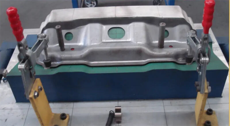
In today's automotive industry, where performance and efficiency are critical, the design and manufacturing of stamping dies play a vital role in ensuring part quality and production stability. At Shaoyi Metal Technology, we bring years of experience in automotive stamping die development, backed by a skilled engineering team and advanced equipment. From structural reviews and process optimization to final delivery, we offer end-to-end technical support tailored to your needs. With a focus on precision manufacturing, rapid response, and cost control, we provide reliable tooling solutions that help your projects move forward smoothly. If you're looking for a trusted partner in stamping die manufacturing, feel free to contact us.

In today's automotive industry, where performance and efficiency are critical, the design and manufacturing of stamping dies play a vital role in ensuring part quality and production stability. At Shaoyi Metal Technology, we bring years of experience in automotive stamping die development, backed by a skilled engineering team and advanced equipment. From structural reviews and process optimization to final delivery, we offer end-to-end technical support tailored to your needs. With a focus on precision manufacturing, rapid response, and cost control, we provide reliable tooling solutions that help your projects move forward smoothly. If you're looking for a trusted partner in stamping die manufacturing, feel free to contact us.