 Small batches, high standards. Our rapid prototyping service makes validation faster and easier —

Why Grain Flow In Forged Engine Parts Matters for Your Business
Understanding Grain Flow and Its Role in Engine Performance
When you're sourcing engine components for high-performance or heavy-duty applications, you've likely heard the term "forged internals" tossed around. But what actually makes forged engine parts superior to their cast or machined counterparts? The answer lies in something you can't see with the naked eye: grain flow.
Imagine the internal structure of metal as millions of tiny crystals packed together. These crystals, or grains, form when molten metal solidifies. The way these grains align—or don't align—determines how your engine components will perform under extreme stress, heat, and repeated loading cycles.
Grain flow refers to the directional orientation of the grains in metal during deformation. In forged engine parts, this means the crystalline structure aligns deliberately along the component's contours, creating continuous pathways that maximize strength exactly where it's needed most.
The Crystalline Blueprint Inside Every Forged Part
So, what is forged internals from a metallurgical perspective? Every piece of metal contains a grain structure—the underlying lattice pattern that forms as the material transitions from liquid to solid. According to Trenton Forging's technical resources, each grain has its own unique orientation, and the boundaries between these grains play a critical role in determining mechanical properties.
When metal undergoes the forging process, controlled pressure and temperature reshape not just the external form but also this internal crystalline architecture. The grain of metal literally flows and realigns to follow the part's geometry. This creates what engineers call "continuous grain flow"—an unbroken pattern that distributes stress evenly throughout the component.
In contrast, cast parts develop random dendritic structures as molten metal cools in a mold. These grains form without any directional purpose, leaving voids and inconsistencies at grain boundaries. Machined parts face a different problem: cutting through a pre-worked billet severs the existing grain pattern, exposing grain ends that become vulnerable to stress, corrosion, and fatigue cracking.
Why Metal Remembers How It Was Shaped
Here's something fascinating about forged engine parts: the metal essentially "remembers" the forces applied during manufacturing. When you're evaluating what are forged internals for your engine build, you're looking at components where every grain has been deliberately positioned to resist the specific stresses that part will encounter.
This matters because cracks in metal tend to propagate parallel to grain boundaries. By aligning grains perpendicular to anticipated stress directions, forging creates natural resistance to crack initiation and growth. For crankshafts experiencing torsional loads, connecting rods under tensile and compressive cycling, or pistons enduring combustion pressures, this directional strength isn't just beneficial—it's essential for longevity and reliability.
The practical takeaway? Understanding grain flow helps you make smarter purchasing decisions. Components with optimized grain flow deliver superior fatigue resistance, impact toughness, and overall durability—qualities that translate directly to reduced warranty claims, fewer field failures, and stronger customer satisfaction.
The Forging Manufacturing Process and Grain Alignment
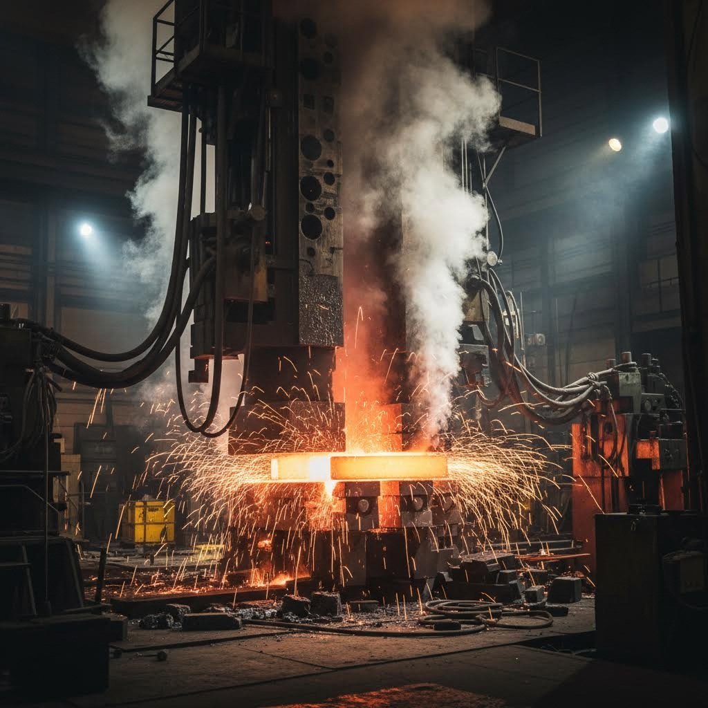
Now that you understand what grain flow is, let's explore how it actually happens. The forging manufacturing process doesn't create aligned grain structures by accident—it's the result of carefully controlled interactions between heat, pressure, and precision tooling. Understanding these mechanics helps you evaluate supplier capabilities and recognize what separates premium forged engine parts from commodity offerings.
How Heat and Pressure Sculpt Metal at the Molecular Level
Picture this: a heated steel billet entering a forging die. At this moment, temperature becomes the master switch controlling everything that follows. According to materials science research from Welong, the metal forging process raises the workpiece above its recrystallization temperature—typically between 50% and 75% of the material's melting point.
Why does this temperature threshold matter so much? Below the recrystallization point, metal resists deformation. The existing grain structure fights back against applied forces, limiting how much you can reshape the material without cracking. But once you cross that thermal threshold, something remarkable happens: the crystalline structure becomes pliable, and grains can reform along new stress lines as pressure is applied.
Think of it like working with clay versus dried concrete. The forging stock, heated to optimal temperature, flows and reshapes under pressure. As the metal deforms, dislocations accumulate within existing grains, causing them to break down into smaller subgrains through a process called dynamic recrystallization. The result? A refined grain structure with enhanced mechanical properties that follows the component's contours precisely.
Temperature control during this process isn't just important—it's critical. As noted by Creator Components' technical documentation, uneven temperature distribution across the workpiece causes inconsistent grain flow. Some areas may experience insufficient recrystallization while others develop excessive grain growth. Either scenario compromises the finished component's performance.
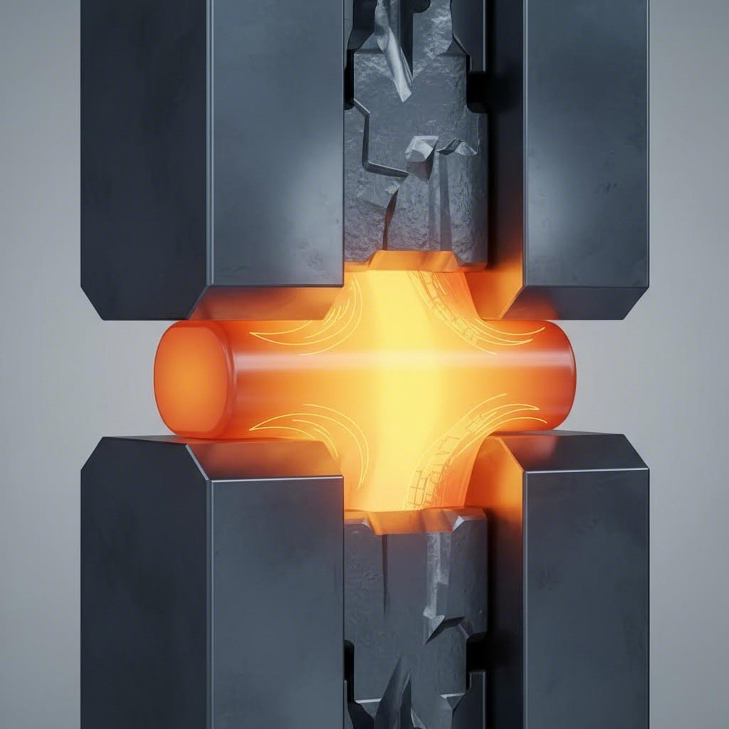
The Science Behind Die-Directed Grain Alignment
Temperature gets the metal ready, but the die determines where those grains actually go. The geometry, contours, and surface features of the forging die directly influence how metal flows during compression—and by extension, how the grain structure aligns throughout the finished part.
When the forging press applies force, metal doesn't simply compress uniformly. It flows toward areas of least resistance, filling cavities and conforming to die surfaces. Well-designed dies promote even material movement, ensuring consistent grain alignment from the component's core to its surface. This is why metals forging for engine applications requires dies engineered specifically for each component type.
Consider the difference between open-die and closed-die forging. In open-die processes, the workpiece is hammered between flat or simple-shaped dies, giving the operator control over material flow but less precision in grain orientation. Closed-die forging—the preferred method for critical engine components—encases the heated billet within precisely machined die cavities, directing grain flow with much greater accuracy.
The following parameters work together to determine grain flow outcomes in the forging material:
- Temperature range: Maintains plasticity while preventing oxidation and excessive grain growth; typically monitored within tight tolerances throughout the operation
- Deformation rate: Higher rates generally produce finer grain structures through accelerated dynamic recrystallization, but must be balanced against strain hardening risks
- Applied pressure: Must be sufficient to completely fill die cavities and ensure grains conform to component geometry without creating internal voids
- Die geometry: Draft angles, fillet radii, and parting line locations control material flow patterns and resulting grain orientation
- Die temperature: Prevents thermal shock and maintains workpiece temperature consistency during forming; especially critical for isothermal forging of aerospace alloys
- Lubrication: Reduces friction between workpiece and die surfaces, promoting smooth material flow and even grain distribution
- Number of forging stages: Multi-stage operations with intermediate heat treatments allow progressive grain refinement and more complex grain flow patterns
What makes the metal forging process particularly effective for engine components is the relationship between deformation rate and grain refinement. As the forging stock deforms rapidly under high pressure, the accumulated strain triggers continuous recrystallization. Each cycle of deformation and recrystallization produces progressively finer grains—and finer grains mean higher strength, following the well-established Hall-Petch relationship in materials science.
This is precisely why a forging process diagram for crankshaft production looks so different from one for piston manufacturing. Each component experiences unique stress patterns in operation, so each requires tailored die designs and process parameters to optimize grain orientation for those specific loading conditions. When evaluating suppliers, asking about their die design capabilities and process controls reveals much about the quality you can expect in the finished components.
Forged vs Cast vs Billet Machined Grain Structures
You've seen how the forging process deliberately aligns grain structure—but how does this compare to the alternatives? When sourcing engine components, you'll encounter three primary manufacturing methods: forging, casting, and billet machining. Each creates fundamentally different metal grain structures, and understanding these differences helps you make informed decisions about component quality and performance expectations.
Three Manufacturing Methods and Their Grain Signatures
Think of grain structure as a component's fingerprint—it reveals exactly how that part was made. Each manufacturing process leaves a distinctive pattern in the grain structure of steel or aluminum, directly impacting how the component performs under stress.
Casting and Random Dendritic Structures
When molten metal pours into a mold and cools, something interesting happens at the crystalline level. Grains form as the metal solidifies, but without any directional force to guide them, they develop in random, tree-like patterns called dendritic structures. According to the Forging Industry Association's technical resources, a casting has neither grain flow nor directional strength, and the process cannot prevent formation of certain metallurgical defects.
These dendritic formations create inconsistencies throughout cast components. Gas porosity—tiny voids trapped as the metal solidifies—weakens the internal structure. Alloy segregation causes some areas to have different chemical compositions than others. For a forged engine block application where uniform strength matters, these variations become serious concerns.
Billet Machining and Interrupted Grain Patterns
Billet-machined parts start with solid aluminum or steel stock that already has an existing grain structure from its original processing—typically extrusion or rolling. The material itself may have decent grain alignment, but here's the problem: machining cuts right through it.
As Frigate's manufacturing analysis explains, machined parts generally have lower mechanical strength because machining cuts through the material's natural grain structure. Every pass of the cutting tool severs grain boundaries, exposing grain ends at the surface. This is particularly problematic in applications involving stainless steel grain direction, where cutting across established grain patterns compromises corrosion resistance alongside mechanical properties.
Forging and Contour-Following Alignment
Forging takes a completely different approach. Instead of accepting random grain formation or cutting through existing patterns, the process actively reshapes the metal grain structure to follow component contours. As noted by Wayken's technical documentation, forging focuses on rearranging the metal's grain structure, beneficially altering the internal structure to make it much denser and stronger than cast or billet alternatives.
The distinction matters most in critical engine components. When grain direction aligns with anticipated stress paths, the component resists failure far more effectively than alternatives where grains either form randomly or get interrupted by machining operations.
What Happens When You Cut Across the Grain
Imagine cutting a piece of wood perpendicular to its grain versus parallel to it. The perpendicular cut creates a rough, weak surface prone to splitting. Something similar happens when machining metal components—except the consequences show up later, under operational stress.
When a cutting tool passes through billet material, it does more than remove unwanted metal. Each cut exposes grain boundaries to the surface, creating potential initiation points for fatigue cracks and stress corrosion. The Forging Industry Association notes that machined bar and plate may be more susceptible to fatigue and stress corrosion because machining cuts material grain pattern.
This phenomenon becomes especially significant in high-performance applications. A connecting rod machined from billet stock might look identical to a forged alternative, but under the repetitive loading of engine operation, those severed grain boundaries become weak points. Cracks initiate at exposed grain ends and propagate along the interrupted boundaries.
Stainless steel grain direction considerations highlight another dimension of this problem. In corrosive environments, grain boundaries exposed by machining become preferential attack sites. This is why critical aerospace and marine engine components almost universally specify forged construction—the continuous grain flow provides both mechanical and corrosion resistance advantages.
The following comparison summarizes how these three manufacturing methods differ across key performance criteria:
| Criteria | Forged Components | Cast Components | Billet-Machined Components |
|---|---|---|---|
| Grain Orientation | Aligned to follow component contours; continuous flow throughout | Random dendritic structures; no directional orientation | Pre-existing grain pattern interrupted by cutting operations |
| Tensile Strength | Highest; typically exceeds 50,000 psi for steel alloys | Lowest; typically 23,000-34,500 psi range | Moderate; typically 30,000-45,000 psi depending on alloy |
| Fatigue Resistance | Superior; continuous grain paths resist crack propagation | Poor; porosity and inclusions create stress concentrations | Moderate; exposed grain ends serve as crack initiation sites |
| Impact Resistance | Excellent; refined grain structure absorbs shock loading | Limited; brittle failure modes under sudden loads | Good for initial impact; compromised at machined surfaces |
| Internal Defects | Minimal; forging pressure eliminates voids and porosity | Common; gas porosity and shrinkage cavities typical | Depends on starting stock quality; machining cannot improve |
| Dimensional Precision | Moderate; may require finish machining for tight tolerances | Variable; depends on mold quality and shrinkage control | Excellent; CNC machining achieves micron-level tolerances |
| Cost Efficiency | Higher initial tooling; lower per-part cost at volume | Lowest per-part cost; economical for complex shapes | Higher material waste; best for prototypes and low volumes |
| Typical Engine Applications | Crankshafts, connecting rods, high-performance pistons | Engine blocks, cylinder heads, intake manifolds | Custom one-off components, racing prototypes, replacement parts |
Notice how the strength characteristics follow directly from grain structure differences. Forged components leverage their aligned grain flow to achieve the highest strength ratings, while cast components suffer from the inherent weaknesses of random grain formation and internal defects. Billet-machined parts fall somewhere between—they start with better material than castings but sacrifice some advantage when machining cuts through the grain.
For buyers evaluating engine component options, this comparison reveals why premium forged parts command higher prices. The manufacturing process doesn't just shape the external form—it fundamentally improves the internal structure in ways that casting and machining simply cannot replicate. The next logical question becomes: exactly which mechanical properties improve, and by how much?
Mechanical Properties Enhanced by Proper Grain Orientation
You've seen the structural differences between forged, cast, and machined components. But what do those differences actually mean when your engine components face real-world stress? The answer lies in three critical mechanical properties: fatigue resistance, tensile strength, and impact resistance. Each responds differently to grain orientation—and understanding these distinctions helps you predict component longevity before failures ever occur.
How Aligned Grains Fight Fatigue Failure
Fatigue failure is the silent killer of engine components. Unlike a sudden break from overload, fatigue happens gradually through millions of loading cycles. Each combustion event, each piston stroke, each crankshaft rotation adds microscopic stress to your components. Over time, tiny cracks initiate and grow until catastrophic failure occurs.
Here's where aligned grain flow becomes your first line of defense. According to comparative manufacturing data from Align Manufacturing, forged parts often exhibit approximately 37% higher fatigue strength than cast counterparts in representative comparisons. Why such a dramatic difference?
Think about how cracks propagate through metal. They don't travel in straight lines—they follow the path of least resistance, typically along grain boundaries. In properly forged components, those grain boundaries run perpendicular to anticipated stress directions. Each time a growing crack encounters a grain boundary, it must change direction and expend additional energy to continue. As JE Pistons' engineering team explains, "the elongated grains, packed tightly together, form walls to prevent the crack from progressing. The crack stops every time it hits a grain boundary."
So what are forged pistons actually doing differently at the molecular level? When you examine a forged piston's crown—the area experiencing maximum combustion pressure—you'll find grains deliberately wrapped around critical stress points like where the pin tower meets the crown. These elongated, tightly compressed grains create additional boundaries exactly where fatigue cracks would otherwise initiate and spread.
The Stress Distribution Advantage of Continuous Grain Paths
Tensile strength and impact resistance respond to grain orientation through a related but distinct mechanism: stress distribution. When external forces act on a component, how that stress travels through the material determines whether it survives or fails.
Continuous grain paths in forged components act like fiber-reinforced structures. When tensile loads pull on a connecting rod, aligned grains share that load across countless grain boundaries working in parallel. According to the manufacturing comparison from Align Manufacturing, this grain alignment contributes to approximately 26% higher tensile strength in forged parts versus cast alternatives.
Impact resistance follows a similar principle but operates on a shorter timescale. When a component experiences sudden shock loading—like detonation in a high-compression engine or an over-rev condition—the aligned grain structure absorbs and distributes that energy more effectively. Random grain patterns in castings concentrate stress at porosity sites and irregular boundaries, often triggering brittle fracture. Forged components, with their refined and oriented grain structures, absorb shock through controlled deformation rather than catastrophic cracking.
The benefits of forging become especially clear when you examine common engine failure modes under cyclic loading:
- Crack initiation resistance: Aligned grains eliminate the exposed grain ends that serve as stress concentrators in machined components; forging strength derives partly from minimizing these vulnerable initiation sites
- Crack propagation barriers: Each grain boundary perpendicular to the stress direction forces cracks to expend energy changing direction, dramatically slowing crack growth rates
- Uniform stress distribution: Continuous grain flow spreads applied loads across larger material volumes, reducing peak stress concentrations that trigger failure
- Enhanced ductility: Properly oriented grain structure steel allows controlled plastic deformation before failure, providing warning signs rather than sudden brittle fracture
- Reduced defect sensitivity: The forging process closes internal voids and porosity that would otherwise amplify stresses around defects
- Improved high-temperature stability: Aligned grains maintain their beneficial orientation even as operating temperatures approach the material's thermal limits
The benefits of forged pistons illustrate these principles in action. A forged piston experiences extreme thermal cycling, combustion pressure spikes, and continuous reciprocating loads. Its crown must resist fatigue from repeated pressure pulses while pin bosses endure tensile and compressive cycling. Without proper grain alignment, cracks would initiate at stress concentrations and propagate through the weakest paths. With optimized grain flow, the piston distributes these stresses across its entire structure, dramatically extending service life.
Understanding these property differences helps you evaluate supplier claims more critically. When a vendor describes their forging process, you now know what questions to ask: How do they orient grain flow relative to primary stress paths? What controls ensure consistent alignment across production runs? The answers reveal whether you're getting true forging strength benefits or just a component that happens to be forged without optimization for your specific application.
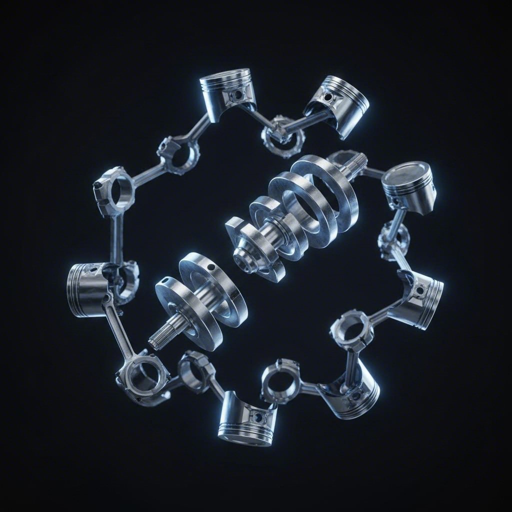
Grain Flow Requirements Across Engine Component Types
Now that you understand how grain orientation enhances mechanical properties, let's get specific. Not all engine components experience the same stresses—and that means grain flow optimization looks different for crankshafts versus pistons versus connecting rods. Each component has unique loading patterns, material requirements, and failure modes that demand tailored grain flow strategies.
Whether you're sourcing forged pistons ls1 builds demand or evaluating 5.7 hemi forged pistons and rods packages, understanding these component-specific requirements helps you distinguish between genuinely optimized forged engine components and generic alternatives that miss the mark.
Crankshafts and the Torsional Stress Challenge
Crankshafts face perhaps the most complex stress environment in any engine. Every combustion event delivers a twisting force through the crankpin, while bearing journals experience continuous rotational loading. The crank web—that transition zone between journals and pins—absorbs concentrated bending stresses with every power stroke.
According to IACS Unified Requirements for steel forgings, crankshafts require special approval when grain flow is needed in the most favorable direction relative to service stresses. Tests must demonstrate that satisfactory structure and grain flow are achieved—this isn't left to chance.
Why such stringent requirements? Torsional loads create shear stresses that spiral along the crankshaft's length. Optimal grain flow runs longitudinally through the main journals and curves through the crank webs to follow these stress patterns. When manufacturers use closed-die forging with properly designed dies, the grain structure literally wraps around each fillet radius where stress concentrations peak.
Steel dominates crankshaft applications for good reason. High-performance forged engine builds typically specify 4340 or similar alloy steels that combine toughness with fatigue resistance. The forging process refines the grain structure while orienting it to resist both the twisting and bending loads that define crankshaft service life.
Why Piston Crowns Demand Radial Grain Patterns
Pistons operate in a completely different stress environment than crankshafts. Instead of torsional loading, they face direct compressive forces from combustion pressure pushing straight down on the crown. High performance pistons must also handle extreme thermal cycling—heating rapidly during combustion, then cooling during intake strokes.
This is where aluminum forging gets interesting. Unlike steel crankshafts, pistons typically use 2618 or 4032 aluminum alloys that balance strength with thermal conductivity. The JE forged pistons manufacturing approach demonstrates how forging creates aligned grain structures in these aluminum alloys, directing material flow to strengthen critical areas.
For piston crowns, the ideal grain pattern radiates outward from center—imagine ripples spreading from a stone dropped in water. This radial alignment distributes combustion pressure evenly across the crown surface and into the ring lands and pin bosses. When you're evaluating je forged pistons or similar premium options, this crown grain orientation directly impacts how the piston handles repeated pressure loading.
Pin boss areas require special attention. These heavily loaded features experience oscillating tension and compression as the connecting rod transmits force. Forging dies must direct grain flow to wrap around pin bores, creating continuous grain paths that resist the fatigue cracking these stress concentrations would otherwise promote.
Connecting Rods and Tensile-Compressive Cycling
Connecting rods bridge the gap between crankshaft rotation and piston reciprocation—and their stress profile reflects this transitional role. During the power stroke, the rod experiences pure compression as combustion pressure drives the piston down. During intake and the latter part of exhaust, that same rod endures tensile loading as the piston decelerates against its own inertia.
This alternating tension-compression cycle makes connecting rods particularly sensitive to grain flow orientation. The ideal pattern runs longitudinally from big end to small end, following the primary stress axis. When forged engine components include connecting rods, the grain should flow smoothly through the beam section without interruption at the parting line where the cap meets the rod body.
Steel connecting rods in performance forged products typically use 4340 or similar alloys, heat-treated to achieve the balance of strength and ductility these cyclic loads demand. Aluminum rods—less common but used in some racing applications—require even more careful grain flow control because aluminum's fatigue behavior is more sensitive to microstructural discontinuities.
Camshafts and Surface Stress Considerations
Camshafts present yet another stress pattern. The cam lobes experience Hertzian contact stresses where they push against valve lifters—highly localized compressive forces that can cause surface pitting and wear. Meanwhile, the cam journals handle bearing loads while the shaft itself transmits drive torque from the timing chain or belt.
Grain flow optimization for camshafts focuses on two areas: longitudinal alignment through the shaft body for torsional resistance, and surface grain refinement at lobe contact areas for wear resistance. Some manufacturers specify induction hardening or nitriding of finished camshafts—the IACS requirements note that forgings intended for surface hardening must be heat treated to a condition suitable for subsequent processing.
The following table summarizes how grain flow requirements differ across major engine component types:
| Component | Primary Stress Types | Optimal Grain Flow Direction | Typical Materials | Critical Areas for Grain Alignment |
|---|---|---|---|---|
| Crankshaft | Torsional shear, bending at webs, bearing loads | Longitudinal through journals, curved through webs following fillet contours | 4340 steel, 4140 steel, microalloyed steels | Fillet radii between journals and webs, oil hole intersections |
| Connecting Rod | Alternating tension-compression, bearing stress at ends | Longitudinal from big end to small end, continuous through beam section | 4340 steel, titanium alloys, 7075 aluminum (racing) | Beam section transitions, bolt boss areas, parting line region |
| Piston | Axial compression, thermal stress, pin boss oscillating loads | Radial across crown, wrapped around pin bores | 2618 aluminum, 4032 aluminum, 2024 aluminum | Crown center, pin boss interfaces, ring land transitions |
| Camshaft | Hertzian contact at lobes, torsion through shaft, bearing loads | Longitudinal through shaft, refined surface grains at lobe contacts | 8620 steel, 4140 steel, cast iron (lower performance) | Lobe contact surfaces, journal bearing areas, drive keyway |
| Valve | Tensile from spring loads, impact at seat, thermal gradients | Longitudinal through stem, radial across head face | Inconel, 21-2N, titanium (racing) | Stem-to-head transition fillet, keeper groove area |
| Rocker Arm | Bending, contact stress at tip and pivot | Longitudinal along arm length, refined at contact points | 4340 steel, 8620 steel, aluminum (roller types) | Pivot bore, valve tip contact area, pushrod cup |
Notice how material selection correlates with stress type and operating environment. Steel dominates where torsional strength and fatigue resistance matter most—crankshafts, connecting rods, camshafts. Aluminum appears where weight savings justify its lower absolute strength, provided grain flow optimization compensates for the material's inherent fatigue sensitivity.
For procurement decisions, this component-by-component analysis reveals which parts most benefit from premium forging processes. A crankshaft with compromised grain flow at fillet radii represents a ticking time bomb regardless of material quality. Conversely, a well-forged piston from a reputable manufacturer delivers the reliability that keeps customers coming back—whether for forged pistons ls1 applications or 5.7 hemi forged pistons and rods combinations.
The practical question becomes: how do you verify that the components you're buying actually achieve these optimal grain flow patterns? That leads directly to understanding quality control and inspection methods—the processes that separate documented quality from marketing claims.

Quality Control and Grain Flow Verification Methods
You've learned why grain flow matters and how different components require specific grain orientations. But here's the critical question: how do you actually know the forging component you're buying has the grain structure the supplier claims? Unlike dimensional measurements you can verify with calipers, grain direction in metal remains invisible to the naked eye. This is where quality control and inspection methods become your window into what's really happening inside those forged engine parts.
Verification isn't optional—it's essential. According to Infinita Lab's metallurgical testing resources, grain flow testing and analysis is a crucial quality control process in industries like aerospace, automotive, and heavy machinery because it assesses the alignment and deformation of grains within metal materials to ensure structural integrity.
Revealing Hidden Grain Patterns Through Acid Etching
Macro-etching remains one of the most revealing inspection methods for visualizing grain direction metal patterns. Think of it as developing a photograph—the acid solution reacts differently with grain boundaries than with grain interiors, creating visible contrast that reveals the flow pattern hidden within the metal.
The process works by taking a cross-section of the forging component and exposing it to specific acid solutions. For steel forgings, manufacturers typically use a 1:1 industrial hydrochloric acid solution heated to 65-80°C, with etching times ranging from 10 to 30 minutes depending on the alloy. As Yogi Machinery's technical documentation explains, this method can reveal macrostructure characteristics including streamline distribution and non-metallic inclusions.
What exactly does macro-etching reveal? The acid preferentially attacks grain boundaries and areas of segregation, creating a topographic map of the metallic grain structure. Inspectors look for several critical indicators: whether flow lines continuously follow the component's contours, whether any folding or turbulence disrupts the pattern, and whether grain flow crosses at critical stress points where it should remain parallel.
For larger forgings where cutting samples isn't practical, cold acid etching offers an alternative. Technicians apply the etching solution directly to accessible surfaces using cotton swabs, revealing grain patterns without destroying the component. This proves particularly valuable for validating production samples while keeping the actual part usable.
Non-Destructive Testing for Grain Flow Verification
While acid etching provides detailed visual evidence, it requires either sacrificing a sample or limiting inspection to surfaces. Non-destructive testing methods fill this gap by evaluating internal quality without damaging the forged component.
Ultrasonic testing stands out as the most versatile non-destructive method for assessing internal grain structure. According to Greg Sewell Forgings' inspection guide, ultrasonic inspection pinpoints the size, location, and distribution of internal flaws with cost-effective, portable equipment and highly accurate findings.
Here's how it works: a transducer converts electrical energy into high-frequency sound waves that penetrate the forging. These waves travel through the metal until they encounter a discontinuity—whether that's a crack, inclusion, void, or significant change in grain orientation. The reflected signal returns to the detector, and its characteristics reveal both the location and nature of what it encountered.
For grain flow verification specifically, ultrasonic testing detects anomalies that indicate improper flow patterns. Abrupt grain direction changes create reflective interfaces. Internal voids that would indicate insufficient material flow during forging appear as distinct echo signatures. While ultrasonic testing can't produce the visual grain map that etching provides, it can rapidly screen large quantities of components and flag those requiring more detailed examination.
The following inspection methods work together to provide comprehensive grain flow verification:
- Visual inspection: The first line of defense; trained inspectors examine surface conditions for folds, cracks, and flow line discontinuities visible after forging and heat treatment
- Macro-etching: Acid-based exposure of grain flow patterns on sectioned samples or surfaces; reveals flow line orientation, folding, turbulence, and whether grains continuously follow component contours
- Microscopic examination: High-magnification metallographic analysis of polished and etched samples; assesses grain size, deformation characteristics, and presence of microscopic defects affecting grain direction metal properties
- Ultrasonic testing: Non-destructive sound wave analysis detecting internal flaws, voids, and discontinuities that indicate grain flow problems; suitable for 100% production screening
- Magnetic particle inspection: Reveals surface and near-surface cracks in ferromagnetic materials by applying magnetic fields and iron particles; effective for detecting grain flow discontinuities that reach surfaces
- Liquid penetrant testing: Capillary action draws colored or fluorescent dye into surface-breaking defects; particularly useful for non-ferromagnetic alloys where magnetic methods don't apply
Metallographic examination provides the most detailed view of metallic grain characteristics. As metallurgical testing protocols indicate, during analysis several aspects of the grain structure are assessed, including grain size, grain orientation, grain deformation, and presence of defects. This microscopic view confirms whether the forging process achieved the desired refinement and alignment.
Sample selection matters tremendously for destructive testing methods. Inspectors must cut samples from locations representative of critical stress areas—not convenient corners where grain flow naturally behaves well. For crankshafts, that means sectioning through fillet radii. For connecting rods, samples come from beam transitions. The goal is verifying grain direction in metal exactly where it matters most for component survival.
What separates premium forging suppliers from commodity sources often comes down to these verification processes. When a manufacturer can show documented macro-etch results, ultrasonic inspection records, and metallographic certification for their production runs, you're seeing evidence of genuine quality control—not just claims about grain flow optimization. Understanding these methods positions you to ask the right questions when evaluating potential suppliers for your forged engine component needs.
How Grain Flow Defects Lead to Engine Part Failures
You've learned how to verify grain flow quality—but what happens when those verification processes fail or get skipped entirely? Understanding how improper grain flow contributes to actual engine failures gives you a failure analysis perspective that most technical resources overlook. When components fail in the field, investigators often trace the root cause back to grain structure defects that were present from the moment the part left the forge.
Sounds dramatic? Consider this: according to research published in Materials journal, defects in forged components "pose significant safety risks as potential initiation sites for catastrophic fracture during operation." Whether you're sourcing crankshafts, connecting rods, or camshafts, understanding these failure modes helps you recognize warning signs before they become warranty claims.
When Grain Flow Goes Wrong and Engines Pay the Price
Imagine a machined forging where the final cutting operation exposes grain ends at a critical stress point. Under cyclic loading, those exposed ends become crack initiation sites. Each engine cycle drives the crack deeper until—often without warning—the component fails catastrophically.
This scenario plays out in three primary ways, each tied to specific grain structure in metals defects:
End Grain Exposure
When grains terminate at a component's surface rather than running parallel to it, you have end grain exposure. This commonly occurs when machining operations remove too much material after forging, or when die design doesn't adequately direct material flow to critical surfaces. The grain boundaries at these exposed ends act like microscopic notches, concentrating stress and providing easy pathways for crack propagation.
Flow Line Discontinuities
Flow lines should follow component contours smoothly, like wood grain wrapping around a naturally curved branch. Discontinuities occur when the forging drawing doesn't account for proper material movement, creating abrupt changes in grain direction. According to the technical analysis of critical forging defects, grain flow disruption "reduces strength and durability, especially under stress" and "makes the part more likely to crack or fail."
Deformation Dead Zones
Perhaps the most insidious defect, deformation dead zones occur when metal doesn't flow properly during the drawing forging process. Research on eccentric camshaft forging demonstrated exactly how this happens: "When the first step became fully filled, a deformation dead zone formed on the eccentric side, where metal flow essentially ceased." As additional metal continued entering the die cavity, it pulled on the stagnant material, creating S-shaped flow lines and eventually cracks when tensile stresses exceeded the material's limits.
Reading Failure Surfaces for Grain Flow Clues
When engine components fail, the fracture surface tells a story. Failure analysts examine these surfaces to determine whether grain flow defects contributed to the failure. Certain patterns reveal specific problems:
Fatigue failures typically show beach marks—concentric rings radiating from the crack initiation point. When that initiation point aligns with a grain flow discontinuity or exposed grain end, the connection becomes clear. The crack didn't start randomly; it started exactly where the grain structure in metals was compromised.
The camshaft study revealed another critical insight: "During normalizing of as-forged components containing these imperfections, atmospheric exposure at defect interfaces initiates accelerated decarburization reactions." This means initial forging defects actually worsen during subsequent heat treatment, deepening cracks and expanding weak zones. A small grain flow problem during forging becomes a major structural defect by the time the component reaches service.
The following grain flow defects represent the most common causes of engine component failures:
- Grain flow disruption: Internal grain structure misaligns or becomes irregular, reducing strength under stress and increasing crack susceptibility; caused by incorrect forging technique, poor die design, or inadequate deformation
- Cold shuts: Surface defects where two metal flows meet but don't properly fuse, creating crack-like weak spots; occur when metal is too cold or die design splits metal flow incorrectly
- Laps and folds: Metal folds over itself without bonding, leaving thin lines or seams that act as stress concentrators; result from excess material, improper die design, or uneven force application
- Internal cracks: Hidden fractures forming when metal experiences excessive stress or uneven flow during forging; particularly dangerous because they're invisible without non-destructive testing
- Improper grain growth: Grains become too large or uneven from excessive heating time, reducing toughness and fatigue resistance; makes components more brittle and likely to crack
- End grain exposure from machining: Finish machining cuts through aligned grain patterns, exposing grain boundaries at critical surfaces; creates preferential sites for crack initiation and corrosion attack
Die design emerges as a recurring theme across these failure modes. The technical analysis of forging defects consistently identifies "poor die design that doesn't guide the metal flow properly" as a root cause. When the forging drawing doesn't account for how metal will actually flow under pressure, the resulting components carry hidden vulnerabilities that only reveal themselves under operational stress.
For buyers, this failure analysis perspective changes how you evaluate suppliers. Do they show evidence of die flow simulation before production? Can they demonstrate macro-etch results from representative samples? Have they analyzed any field failures to trace root causes back to grain flow issues? The answers reveal whether a supplier truly understands grain flow optimization—or simply stamps out parts hoping for the best.
Selecting Quality Forged Components with Optimal Grain Flow
You now understand whats forging does at the metallurgical level, how grain flow impacts mechanical properties, and what defects to watch for. But here's the practical question every procurement professional faces: how do you translate this knowledge into smart purchasing decisions? Selecting forged engine components with optimal grain flow requires more than comparing price quotes—it demands evaluating suppliers on their ability to consistently deliver the internal quality that determines component longevity.
Think of supplier selection as building a partnership rather than just placing orders. The components you source become part of your product's reputation. When an engine forge produces parts with compromised grain structure, your customers experience the failures—not the supplier who cut corners on die design or skipped heat treatment verification.
What Quality Certifications Reveal About Grain Flow Control
Certifications serve as your first screening tool for separating serious manufacturers from commodity suppliers. But not all certifications carry equal weight when it comes to grain flow consistency in forging materials.
According to industry sourcing guidelines, ISO 9001 certification confirms a supplier has documented, audited quality management processes—but it doesn't certify individual product quality. What it does guarantee is that the supplier has consistent procedures for controlling production, calibrating equipment, and addressing problems. This foundation matters, but automotive applications demand more.
For engine components specifically, IATF 16949 certification represents the gold standard. This automotive-specific quality management system builds on ISO 9001 requirements with additional controls tailored to the unique demands of automotive supply chains. Suppliers certified to IATF 16949 must demonstrate process capability, implement advanced product quality planning, and maintain rigorous traceability—all factors that directly impact grain flow consistency across production runs.
Why does this matter for your forged build? IATF 16949-certified suppliers like Shaoyi (Ningbo) Metal Technology operate under continuous improvement requirements that extend to every aspect of their precision hot forging solutions. Their die designs undergo validation, heat treatment processes follow documented parameters, and grain flow verification becomes part of standard quality protocols rather than occasional spot-checks.
When evaluating potential suppliers for forgeable materials and finished components, prioritize these criteria:
- IATF 16949 certification: Confirms automotive-grade quality management with advanced process controls, statistical process capability requirements, and continuous improvement mandates specific to automotive supply chains
- ISO 9001 certification: Establishes baseline quality system documentation, calibration programs, and corrective action procedures that support consistent manufacturing
- Material Test Report (MTR) availability: Demonstrates traceability from raw material through finished component; every part should link to certified chemistry and mechanical properties
- In-house metallurgical testing capability: Suppliers with their own macro-etching, microscopy, and hardness testing can verify grain flow without relying on third-party labs that may delay quality feedback
- Non-destructive testing (NDT) certification: Look for ASNT Level II or III certified technicians for ultrasonic and magnetic particle inspection of production components
- Heat treatment documentation: Suppliers should provide temperature-time charts proving their furnaces followed specified cycles for normalizing, quenching, and tempering
- Die design and simulation capability: Advanced suppliers use computer simulation to predict material flow before cutting dies, preventing grain flow defects at the design stage
Supplier Questions That Separate Premium Forging from Commodity Parts
Certifications open the door, but conversations reveal the truth about a supplier's actual capabilities. As Canton Drop Forge's sourcing guide emphasizes, asking the right questions helps you distinguish genuine excellence from marketing polish.
Start with raw material controls. What forging stock does the supplier keep in inventory, and how do they verify incoming material quality? A supplier who orders alloys as-needed might introduce delays and variability compared to one maintaining certified inventory. Ask to see their material receiving inspection procedures and how they handle nonconforming stock.
Process control questions cut to the heart of grain flow quality. How does the supplier determine optimal forging temperature for each alloy? What controls prevent under-forging or over-forging? How do they verify die fill and material flow during production runs? According to sourcing best practices, a knowledgeable supplier will discuss the application to help recommend appropriate materials and explain why specific process parameters matter for your component.
Quality verification deserves detailed inquiry. Ask specifically: "How are my custom forged parts tested?" As industry experts note, quality assurance shouldn't be an afterthought—it should remain at the forefront of the forging process. Request examples of macro-etch results, ultrasonic inspection reports, and metallographic documentation from previous production runs.
Don't overlook supply chain questions. What steps of the forging process are outsourced? Some suppliers subcontract heat treatment or machining, which introduces quality variables outside their direct control. Understanding forged internals meaning includes recognizing that the entire process chain—from billet to finished part—affects final quality.
Finally, evaluate partnership potential. How would the supplier handle a situation where inspection reveals grain flow below specification? Their answer reveals whether quality culture exists beyond the certification plaque on the wall. The best suppliers—those who understand that your success depends on their consistency—will describe quarantine procedures, root cause investigation protocols, and proactive customer communication.
For automotive applications specifically, suppliers with proximity to major logistics hubs accelerate your supply chain. Manufacturers located near Ningbo Port, for example, can deliver globally compliant components with streamlined export documentation. This logistics advantage compounds the value of rigorous quality control—you receive verified components faster and more predictably.
The investment you make in supplier evaluation pays dividends across every component they provide. When you source from partners who understand grain flow optimization at a fundamental level—and prove it through certifications, documentation, and transparent communication—you're not just buying forging materials. You're building reliability into every engine that carries your brand.
Frequently Asked Questions About Grain Flow in Forged Engine Parts
1. What is grain flow in forging?
Grain flow refers to the directional orientation of metal's crystalline structure during plastic deformation. In forged engine parts, controlled heat and pressure align grains along component contours, creating continuous pathways that distribute stress more effectively. This differs from cast parts with random grain patterns or machined parts where cutting interrupts existing grain structures. Proper grain flow orientation significantly improves fatigue resistance, tensile strength, and impact resistance in critical engine components like crankshafts and connecting rods.
2. Do forgings have grain direction?
Yes, forgings develop distinct grain directions based on how the metal flows during the forging process. Rectangular forgings typically have three grain directions: longitudinal (L), long transverse (LT), and short transverse (ST). Round forgings have two general grain directions. The forging process controls grain orientation through proper die design and hot working procedures, allowing grains to flow around corners and follow part contours. This directional grain structure is precisely why forged components outperform cast alternatives in demanding engine applications.
3. What does grain flow forged mean?
Grain flow forging describes a manufacturing method where metal's natural crystalline grain structure is deliberately aligned during multiple forging stages. Starting from a single billet, the process uses controlled temperature, pressure, and precision dies to direct how grains orient within the finished component. This technique enhances the part's integrity, consistency, and durability by positioning grain boundaries perpendicular to anticipated stress directions. Engine components manufactured this way exhibit superior resistance to fatigue cracking and mechanical failure.
4. What are the disadvantages of a forged engine?
Forged engine components carry higher upfront costs due to specialized equipment, skilled labor, and intensive energy requirements. The forging process demands precision die tooling and careful temperature control, making it less suitable for budget-conscious or low-volume applications. Additionally, forged parts often require finish machining to achieve tight tolerances, adding processing steps. However, for high-performance or heavy-duty applications, the superior fatigue resistance, impact strength, and longevity of forged components typically justify the investment through reduced warranty claims and extended service life.
5. How does forging affect grain structure compared to casting and machining?
Forging actively reshapes metal's grain structure to follow component contours, creating aligned grain flow that maximizes strength at critical stress points. Casting allows grains to form randomly as molten metal solidifies, resulting in dendritic structures with potential porosity and segregation defects. Machining cuts through pre-existing grain patterns, severing grain boundaries and exposing grain ends that become crack initiation sites. IATF 16949-certified manufacturers like Shaoyi implement rigorous quality controls to verify grain alignment through macro-etching and ultrasonic testing.