 Small batches, high standards. Our rapid prototyping service makes validation faster and easier —

What Is Metal Stamping: Tooling, Tolerances, And True Costs
What is Metal Stamping Explained Simply
Ever wondered how so many everyday metal parts—from electrical covers to automotive brackets—are made with such precision, speed, and consistency? The answer often lies in a process called metal stamping. If you’re new to manufacturing or just curious about how flat metal sheets become complex, functional components, this chapter will break down what is metal stamping in clear, practical terms.
Definition and Core Principles
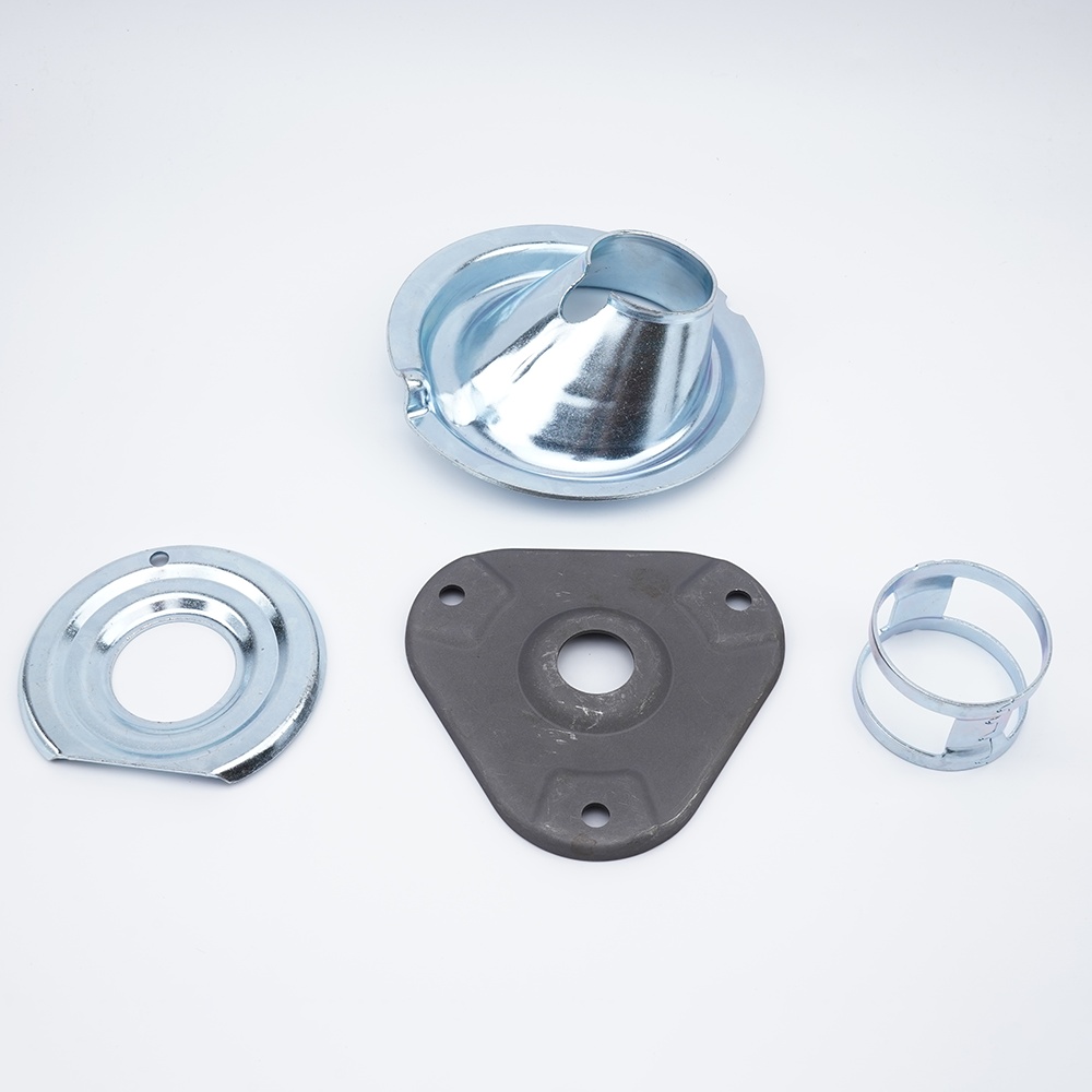
At its core, metal stamping is a manufacturing process that uses a press and specially designed dies to shape flat metal sheets into specific forms. In simple words, stamping means pressing metal into a desired shape using matched tools. The sheet metal—either in coil or blank form—is placed into a stamping press, where a die (the mold) and punch (the forming tool) work together to cut, bend, or form the metal into a part. This process is highly repeatable and cost-effective, especially for large quantities and complex geometries.
The definition of stamped part refers to any metal component produced through this pressing and forming process, typically characterized by tight tolerances, consistent features, and a smooth finish.
Common Operations in Stamping
So, what is stamping in practice? It’s not just one action, but a family of operations performed by the press and die set. Here are some typical stamping applications and techniques:
- Blanking: Cutting out the basic shape or outline from the sheet metal.
- Piercing: Punching holes or slots into the material.
- Bending: Forming straight or angled bends in the metal.
- Forming: Shaping the metal into curves or contours.
- Drawing: Pulling the metal into a deeper shape, like a cup or shell.
Some stamping examples you’ll find in daily life include:
- Electrical connectors and contacts
- Metal brackets and mounting clips
- Enclosure covers and panels
- Automotive reinforcement plates
- Appliance frames and housings
Where Stamping Fits in Metalworking
Within the broader field of metalworking, stamping is one of several pressworking methods. Unlike machining—which removes material—or forging—which reshapes metal through heat and compression, stamping forms the part at room temperature with minimal waste. This makes it ideal for high-volume production where speed, cost, and repeatability are critical.
Stamping is especially valued in industries like automotive, electronics, aerospace, and medical devices, where large numbers of identical parts are required and tight tolerances are essential.
How the Stamping Process Works
- Flat metal (sheet or coil) is loaded into the stamping press.
- The press cycles, bringing the die and punch together to perform operations like blanking, piercing, or bending.
- The part is shaped in one or more steps, often moving through several stations for complex geometries.
- Finished pieces are ejected, sometimes followed by secondary processes like trimming or deburring.
Key takeaway: Metal stamping uses a press and matched dies to shape flat metal into precise, repeatable parts—making it a backbone process for countless stamping applications across modern industry.
Understanding the stamping meaning and its role in manufacturing helps you appreciate why this process is the go-to solution for efficient, scalable production of metal components. As you continue through this guide, you’ll see how tooling, tolerances, and smart design choices all play a role in delivering high-quality stamped parts.
How Sheet Metal Stamping Works from Coil to Part
Imagine watching a flat coil of metal transform into a finished bracket, connector, or cover in just seconds. Sounds complex? Let’s break down the sheet metal stamping process—from raw material to the final part—so you can see how stamping presses, dies, and feed systems come together to deliver precision at scale.
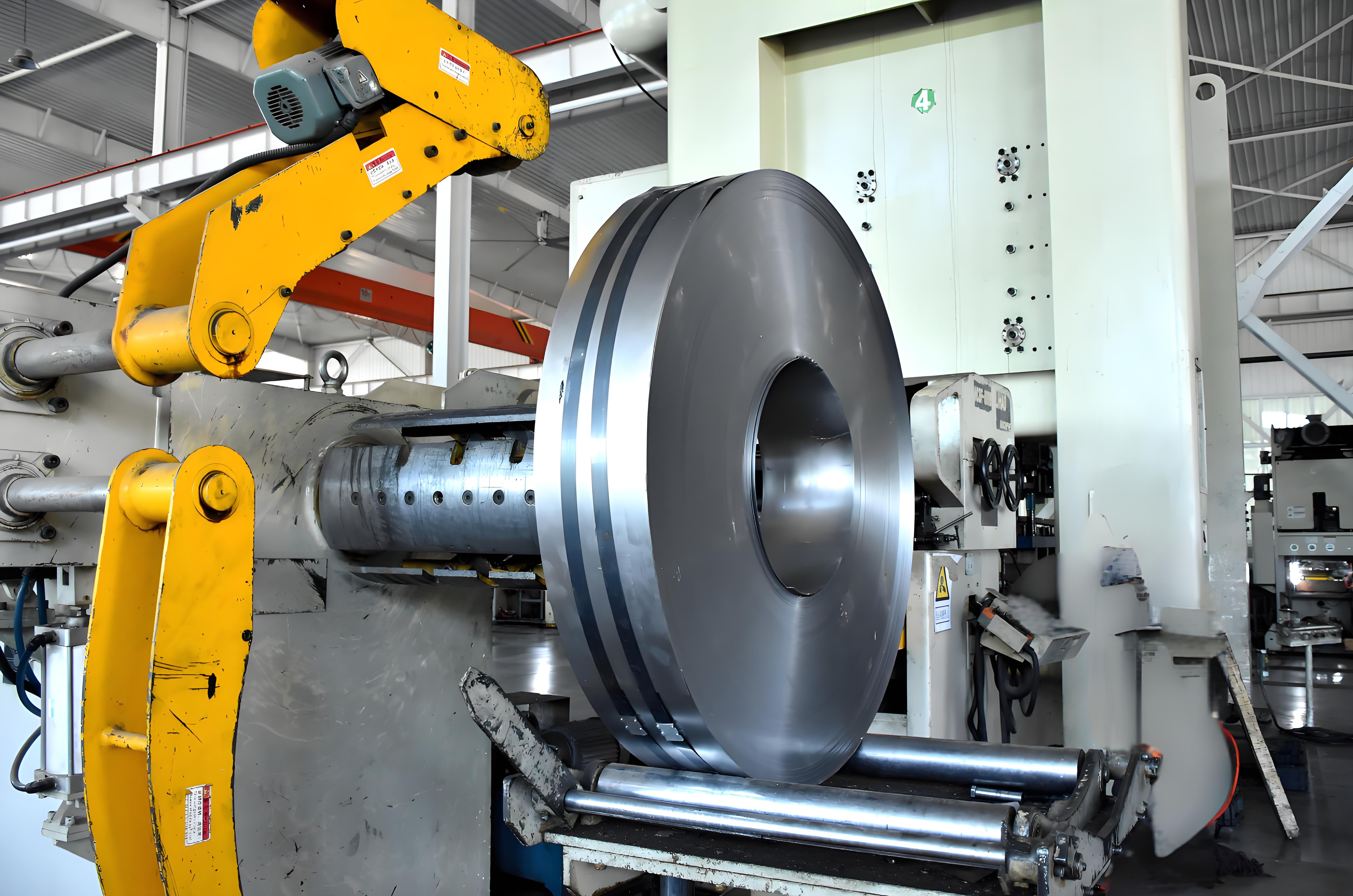
From Coil or Sheet to Blanks
It all starts with the raw material: flat metal, typically supplied as large coils or pre-cut sheets. These coils are unwound and fed into automated lines, where the metal is straightened and lubricated to reduce friction during forming. Material is then advanced into the stamping press, often by precision rollers or automated feeds, ensuring exact positioning for each press cycle.
Before any forming happens, the material is usually cut into manageable shapes called blanks. This blanking operation defines the part’s outline and is the first key step in the stamping process in manufacturing. The goal? To maximize material use and minimize scrap, setting the stage for efficient production.
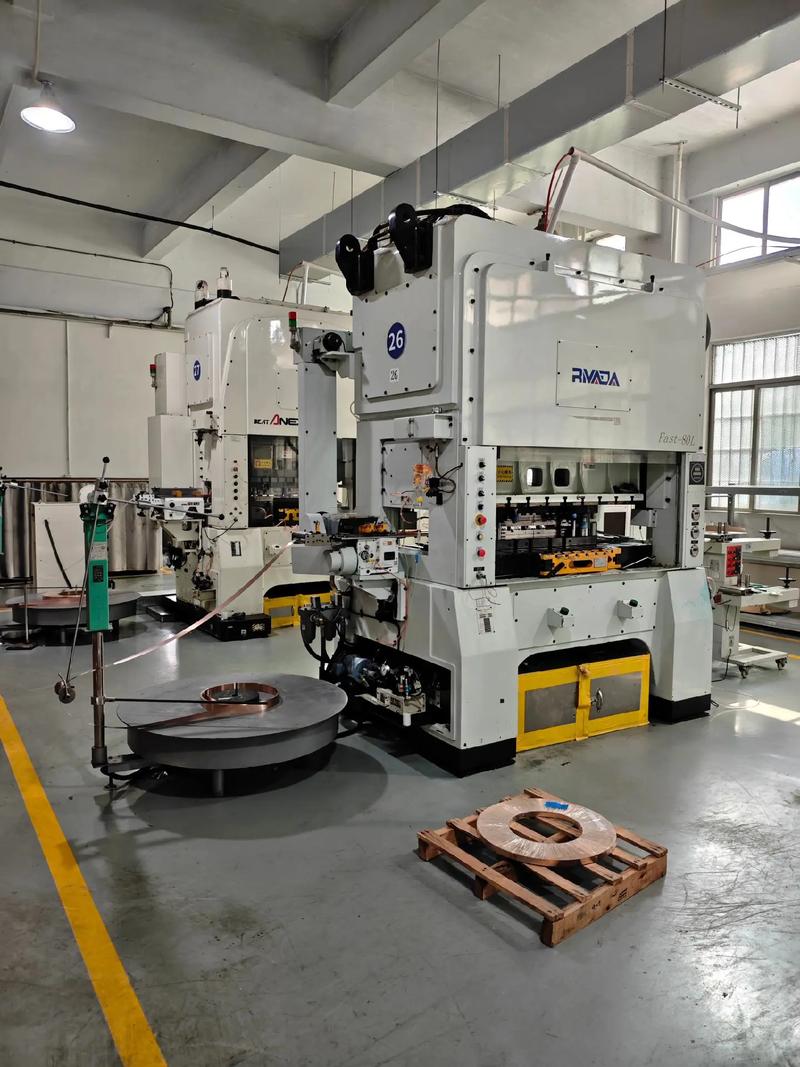
Inside the Stamping Press
Once the blank (or continuous strip) is in place, the real action begins. The metal stamping press delivers tremendous force—measured in tons—using one of several drive types: mechanical, hydraulic, servo, or pneumatic. Each press type offers unique advantages:
- Mechanical presses: Fast and powerful, ideal for high-speed, high-volume runs.
- Hydraulic presses: Offer precise control and are well-suited for forming deeper or more intricate parts.
- Servo presses: Combine speed with programmable motion, allowing for advanced control of stroke and dwell time.
- Pneumatic presses: Use air pressure for lighter-duty stamping applications.
The press’s tonnage (force), stroke (distance traveled per cycle), and speed are matched to the part’s size, material, and complexity. Die clearance—the gap between punch and die—must be carefully set for clean cuts and consistent features. Too tight, and the die wears quickly; too loose, and parts may have burrs or imprecise edges.
Die Sets and Tooling Actions
At the heart of the metal stamping process are custom dies—precision tools that cut, bend, and shape the metal. Each die set typically includes:
- Punch: The part of the die that pushes into the metal, creating holes, shapes, or bends.
- Die: The matching cavity or surface that supports the metal and defines the finished shape.
- Stripper: Removes the formed part from the punch after each cycle.
- Guide pins: Ensure perfect alignment between punch and die, maintaining tight tolerances.
Depending on design, dies may perform one operation per cycle (simple dies) or multiple operations in sequence (progressive or compound dies). In a progressive die setup, for example, a strip of metal advances through several stations, with each station performing a different step—like piercing, bending, or forming—until the finished part is cut free at the end.
Typical Sequence in the Stamping Process
- Material preparation (coil unwinding, straightening, lubrication)
- Blanking or piercing (defining the part’s basic shape or features)
- Forming or drawing (bending or shaping into three-dimensional geometry)
- Restrike or coining (tightening tolerances or adding fine details)
- Deburring and secondary operations (removing sharp edges, adding coatings, or further assembly)
Key insight: The accuracy of material feed and precise die alignment are critical—small deviations can lead to defects, wasted material, or costly downtime. Modern stamping machines often use sensors and automation to monitor every cycle, ensuring consistency and quality with every press stroke.
By understanding each stage of the sheet metal stamping process, you’ll appreciate how stamping presses, dies, and feed systems work together to create high-quality metal parts—fast, repeatable, and ready for the next step in manufacturing. Next, we’ll explore how your choice of metal impacts the process and the final product’s performance.
Choosing Materials for Metal Stamping Success
When you picture a stamped part—maybe a lightweight bracket, a shiny cover, or a complex connector—have you ever wondered why it looks and performs the way it does? The answer often comes down to the metal stamping materials selected at the start. Choosing the right alloy isn’t just a technical detail; it’s the foundation for part quality, cost, and even how easily your design can be manufactured.
Choosing the Right Alloy
So, what’s the best metal for stamping? It depends on your application’s needs: strength, weight, corrosion resistance, conductivity, and even appearance. Here’s a quick side-by-side comparison to help you see how common metals stack up for stamping applications:
| Material | Formability | Strength | Corrosion Resistance | Typical Uses |
|---|---|---|---|---|
| Steel (Carbon/HSLA) | Good | High | Moderate (can be coated) | Brackets, chassis, structural parts |
| Stainless Steel | Varies (304: excellent, 400-series: moderate) | High | Excellent | Medical housings, food equipment, covers |
| Aluminum | Excellent | Moderate | Good | Lightweight panels, automotive trim, electronics |
| Copper/Brass | Very High | Low-Moderate | Good | Electrical connectors, decorative parts |
Formability and Springback Considerations
Imagine trying to form a deep cup or a crisp bend—some metals make this easy, others fight back. Formability describes how well a metal can be bent, drawn, or stretched without cracking. For instance, aluminum stamping is favored for complex shapes thanks to its ductility, while some stamped steel grades excel in strength but may require more force and careful tooling to avoid tearing. Stainless steel stamping is often chosen for parts exposed to harsh environments, but keep in mind that high-strength grades can have more springback, making precise bends trickier.
- Steel/HSLA: Good for strong brackets and frames; higher strength means more springback but great for load-bearing parts.
- Stainless Steel: Excellent for corrosion resistance; 304 is highly formable, while 400-series or martensitic types may need extra care.
- Aluminum: Ideal for deep draws and lightweight needs; less springback, but softer grades can scratch if not handled properly.
- Copper/Brass: Superb for intricate, thin, or coined features; not for heavy loads, but unbeatable for conductivity and fine detail.
Surface and Post-Processing Implications
Your choice of metal for metal stamping also affects surface finish, downstream coating, and even tool life. For example, stamped aluminum resists corrosion naturally, often skipping extra plating steps, while stamped steel may need coatings or galvanizing for outdoor use. Stainless steel’s finish is prized in food and medical settings, but it can be tough on dies, requiring robust tooling and regular maintenance.
-
Checklist for Matching Material to Operation:
- Need deep drawing? Choose highly ductile grades (aluminum, 304 stainless, soft copper).
- Embossing or coined features? Softer metals like brass or aluminum are best.
- High wear or high-volume production? Opt for steels with coatings or hardenable alloys to extend die life.
- Corrosive environments? Stainless or properly coated steel is key.
- Electrical conductivity? Copper or brass alloys shine for connectors and terminals.
Ultimately, the material you select will influence not only how your part is formed, but also the achievable features, tooling wear, and the finishing steps required. By considering these factors early, you’ll set your stamping project up for success—whether you’re producing stamped aluminum panels for electronics, stamped steel brackets for automotive, or delicate copper terminals for electrical systems.
Key takeaway: The right metal stamping materials balance formability, strength, and finish to match your application—saving time, reducing costs, and ensuring your parts perform as intended.
Next, we’ll dive into the design rules that help you get the most out of your chosen material and avoid costly rework in the stamping process.
Design for Metal Stamping Rules That Prevent Rework
Ever spent hours on a stamping design only to discover late-stage issues—cracks near bends, distorted holes, or features that can’t be formed in one shot? It’s a common frustration, but with the right design-for-manufacturability (DFM) approach, you can dramatically reduce rework, scrap, and costly tooling changes. Let’s break down the essential rules and best practices behind sheet metal stamping design—so your parts move smoothly from CAD to production floor.
Drawing and Tolerance Callouts That Help
Imagine handing off a drawing that leaves nothing to guesswork. Clear, unambiguous drawings are the backbone of precision stamping. Here’s what you’ll want to include:
- Use datum schemes that reflect how the part will be fixtured and measured in production—typically, reference a primary flat surface, a key hole, or an edge.
- Apply GD&T (Geometric Dimensioning & Tolerancing) symbols for critical features—like hole location, flatness, or parallelism—so the stamping team knows where tight control is essential and where it’s not.
- Specify tolerances realistically: Tight tolerances increase tooling cost and maintenance. For most features, allow the widest possible tolerance that still meets function.
- Flag features that require secondary operations (like tapped holes or extra-fine surface finishes) to avoid confusion at quoting.
- Communicate coating or plating thicknesses if they affect final dimensions.
When you align your drawing callouts with the actual capabilities of stamping technology, you’ll avoid unnecessary back-and-forth and keep costs in check.
Feature Spacing and Relief Guidelines
Ever wonder why holes sometimes bulge or tear near an edge? Or why tabs might snap off after forming? Smart feature placement is at the heart of robust metal stamping techniques. Here are proven rules, based on industry standards and reference data:
- Minimum hole diameter: For ductile metals like aluminum, keep hole diameters at least 1.2× material thickness; for harder materials (e.g., stainless steel), use 2× thickness. Smaller holes risk tool breakage and poor edge quality.
- Slot width: Should be at least 1.5× the material thickness for clean punching and to avoid premature die wear.
- Distance from hole to edge: Place holes or slots a minimum of 2× material thickness from the nearest edge. Closer spacing can cause bulging or tearing during stamping.
- Distance from hole to bend: For holes less than 0.100" in diameter, keep them at least 2× material thickness plus the bend radius away from the bend line. Larger holes need 2.5× thickness plus the radius.
- Bend radii: For ductile metals, use a bend radius equal to or greater than the material thickness. For less ductile or hardened alloys (like 6061-T6 aluminum), increase the minimum bend radius to several times the thickness to prevent cracking (source).
- Bend relief: Add relief notches at the intersection of bends and edges—width at least half the material thickness—to prevent tearing or stress concentration.
- Embosses and coined features: Limit emboss depth to three times material thickness to avoid thinning or fracture.
- Tabs and notches: Follow similar rules as holes and slots—mind spacing and size to ensure robust forming and easy ejection.
- Grain direction: Align bends perpendicular to grain direction when possible to minimize cracking, especially in less ductile alloys.
By following these guidelines, you’ll design features that form cleanly and consistently—reducing the risk of defects and maximizing tool life.
Progressive Versus Transfer Die Design Choices
Choosing between progressive and transfer stamping isn’t just about part geometry—it’s about volume, complexity, and cost. Here’s how each approach shapes your design decisions:
- Progressive dies: Best for high-volume production of small-to-medium parts with multiple features. Each station adds a feature as the strip advances, enabling rapid, repeatable production.
- Transfer dies: Ideal for larger, more complex parts or those requiring rotation, deep draws, or unique forming steps. Parts are moved between stations by a transfer system, allowing more flexibility in operations (source).
- Consider transfer dies when you need significant part rotation, thick or expensive materials, or when the part shape makes progressive die nesting inefficient.
- For both die types, plan the sequence of operations to distribute forming stresses and avoid overloading any single station.
Early collaboration with your stamper will help you choose the right die strategy and avoid late-stage surprises.
DFM Checklist: From Concept to Production
| Milestone | DFM Questions to Ask |
|---|---|
| Concept |
|
| Pre-Quote |
|
| Pre-Production |
|
Key takeaway: Align your functional tolerances and design features with the true capabilities of your chosen stamping process—overly tight specs or complex features can drive up cost without adding value.
By embedding these DFM principles into your sheet metal stamping design process, you’ll unlock the full potential of modern metal stamping techniques—achieving robust, repeatable parts while minimizing rework and delays. Next, we’ll explore how the right die tooling choices can further streamline your path to production.
Inside the Die Tooling That Makes Stamping Possible
When you picture a flat sheet of metal transforming into a complex, finished part, the real magic happens inside the metal stamping die. But what goes into designing, building, and maintaining these essential tools? Let’s explore the types of dies, the materials that keep them running, and the maintenance routines that ensure your stamping process stays on time and on budget.
Die Types and When to Use Them
Ever wondered why some dies are simple and others seem like miniature factories? The answer lies in matching die type to production needs. Here’s a side-by-side look at the major die types used in metal stamping tooling:
| Die Type | Best For | Complexity | Production Volume | Changeover Time | Scalability |
|---|---|---|---|---|---|
| Single-Station Die | Simple shapes, low-volume runs | Low | Small batches | Fast | Limited |
| Progressive Die | Complex parts, multiple features | High | High (mass production) | Slow (more setup) | Excellent |
| Compound Die | Parts needing inner and outer shapes in one stroke | Moderate | Medium batches | Moderate | Some |
| Transfer Die | Large or deep-drawn parts, unique forms | Moderate-High | Medium to high | Long (complex setup) | Good |
For example, custom metal stamping dies are often built as progressive dies for high-speed, high-volume jobs—think automotive connectors or appliance frames. Single-station dies are perfect for prototyping or small batch runs when flexibility and low cost matter most. Transfer dies shine when you need to move a part between operations, like forming deep shells or large brackets.
Tool Steels, Coatings, and Tool Life
Why do some steel stamping dies last for millions of cycles, while others need frequent repair? The answer is in the materials and coatings used. Most dies are crafted from hardened tool steel, chosen for its ability to resist wear, cracking, and deformation under repetitive loads. For especially tough jobs or abrasive materials, advanced coatings (like nitriding or carbide layers) are applied to further extend tool life and reduce friction.
But even the best metal stamping die faces wear. Common failure modes include:
- Abrasive wear: Gradual material loss from repeated contact with the workpiece.
- Adhesive wear: Microwelds between die and part surface, leading to tearing and surface roughening.
- Galling: Sheet metal sticking to the die, especially in soft or sticky alloys.
- Chipping/cracking: Stress at sharp corners or from excessive press force.
Using the right tool steel and surface treatments—and choosing the correct die electrical grease for lubrication—can dramatically reduce these issues and keep your sheet metal die press running smoothly.
Maintenance, Spares, and Lead-Time Planning
Imagine your production line grinding to a halt because of an unexpected die failure. Preventive maintenance is critical to avoid costly downtime. Typical routines include:
- Regular inspection for wear, chipping, or cracks
- Cleaning and relubricating die surfaces
- Replacing worn punches, guide pins, or springs
- Keeping spare inserts and critical components on hand
- Tracking cycles to schedule planned maintenance before failures occur
Planning for maintenance downtime—and building it into your production schedule—helps control per-part costs and ensures lead times are met. Early design freezes are also crucial: locking the design before tooling begins allows for accurate quoting, efficient tool build, and smoother launch. When you amortize tooling costs over higher volumes (EOQ), the per-part impact of even complex metal stamping dies drops significantly (source).
-
Critical Die Design Levers Affecting Cost:
- Number of stations (more stations = more complexity, higher cost)
- Pilots and lifters (for precise part movement and ejection)
- Cams (for side-action features)
- Sensors (for in-die quality checks and error-proofing)
- Material selection and coatings
Key takeaway: The right combination of die type, material, and maintenance planning ensures reliable, cost-effective stamping—keeping your production on track and your parts within spec.
With a solid understanding of metal stamping tooling and die maintenance, you’re ready to explore how process planning and press selection further impact cost, quality, and delivery in the next stage of your metal stamping journey.
From RFQ to Press Plan for Engineered Stamping
When you’re tasked with turning a design into thousands—or even millions—of high-quality stamped metal parts, where do you start? The answer lies in meticulous planning, smart equipment selection, and a deep understanding of the stamping manufacturing process. Let’s walk through how process engineers bridge the gap from quoting to full-scale production, ensuring every part meets spec, every cycle runs efficiently, and every challenge is anticipated before the first sheet is loaded.
Press and Feed Selection Criteria
Imagine you’ve just received a new RFQ for a complex bracket. Before any metal moves, engineers evaluate several key factors to choose the right metal stamping equipment:
- Material type and thickness: Thicker or harder metals require higher press tonnage and robust dies. Softer or thinner metals might run on lighter-duty presses but may need gentler handling to avoid scratches or distortion.
- Part size and complexity: Larger or more intricate parts might need a bigger industrial stamping press and specialized feed systems.
- Annual and batch volume: High-volume jobs often justify investment in automated coil feeders and advanced sheet metal stamping equipment to maximize throughput and consistency.
- Required features: Deep draws, tight bends, or multiple pierced holes can dictate the press stroke length and die complexity.
Choosing the right press feeder system is also critical. Options include air, roller, servo, gear, and clamp feeders—each suited for different material types, thicknesses, and production speeds. For example, roller feeders excel in high-speed runs, while servo feeders are preferred for thick or variable materials that require frequent die changes. The goal is always to match the stamping machine for metal to the job for optimal productivity and part quality.
Sequencing Operations Across Stations
Once the right metal stamping press machine is chosen, engineers plan the step-by-step operations needed to transform raw material into finished parts. This involves:
- Deciding between coil-fed progressive dies (for high-volume, multi-step parts) or blank-fed single-station dies (for prototypes or short runs).
- Mapping each forming, piercing, or bending operation to specific die stations—minimizing tool wear and balancing forces to prevent part distortion.
- Integrating lubrication and cooling steps to reduce friction, extend tool life, and maintain part quality.
- Designing scrap removal paths and optimizing material utilization to reduce waste and lower costs.
Automation plays a big role here: coil feeders, automated part ejection, and in-die sensors all help keep production moving smoothly, reduce manual handling, and catch errors early.
In-Process Controls and Ejection
What keeps a high-speed stamping line running with minimal scrap and downtime? The answer is a mix of real-time monitoring, robust error-proofing, and smart ejection systems. Here’s how engineers ensure every part meets the mark:
- Using sensors to detect misfeeds, double sheets, or part jams before they cause tool damage or defects.
- Employing force and position monitoring to spot variations in press cycles, which can indicate tool wear or material inconsistencies.
- Designing ejection systems—like air blasts, strippers, or mechanical pushers—to remove parts cleanly and prevent pile-ups.
- Implementing scrap chutes or conveyors to keep the workspace clear and safe.
These measures not only protect expensive production metal stamping tools but also boost overall efficiency and part quality.
Workflow: From RFQ to First Article Approval
- RFQ data review: Engineers analyze drawings, specs, annual volume, and critical features.
- Press and die selection: Match part requirements to available metal stamping equipment and dies.
- Process planning: Sequence operations, select feed systems, and design in-die controls.
- Prototype or pilot run: Build and test dies, adjust process parameters, and confirm part feasibility.
- Quality verification: Inspect first-article parts against all specs and tolerances.
- Production launch: Ramp up to full-speed production metal stamping with ongoing monitoring and maintenance.
RFQ Inputs Checklist for a Smooth Start
- Material specification (type, grade, and thickness range)
- Estimated annual and release volumes
- Critical-to-quality features and tolerances
- Finished part dimensions and drawing revision
- Surface finish or coating requirements
- Packaging and delivery preferences
- Special requirements (e.g., traceability, certifications)
Key insight: By investing time upfront in detailed process planning, equipment selection, and in-line controls, you set the stage for consistent, high-quality output—making your stamping manufacturing process both reliable and cost-effective.
With your press plan in place, the next step is to ensure every part meets spec—so let’s explore how quality tolerances and inspections keep your stamped parts on target.
Quality Tolerances and Inspection for Stamped Parts
When you receive a shipment of stamped sheet metal, how can you be sure each piece will fit, function, and last as intended? That’s where quality stamping, precise tolerances, and thorough inspection come into play. Let’s break down what it takes to ensure every batch of stamped parts meets your requirements—without costly surprises down the line.
Achievable Precision Factors
Imagine producing thousands of metal stamping parts—each with intricate bends, holes, and forms. How close can you get to the drawing’s dimensions? The answer depends on several factors:
- Process type: Operations like blanking and piercing typically achieve tighter tolerances than deep drawing or complex forming.
- Material properties: Softer or thinner metals allow for finer details, while harder or thicker materials may require looser tolerances to prevent cracking or excessive tool wear.
- Tooling condition: Sharp, well-maintained dies produce more consistent stamped metal components than worn tools.
- Press accuracy and setup: Modern stamping presses with precise alignment and feed control help maintain repeatability across production runs.
Designers and engineers must balance the need for precision with what’s practical in manufacturing. Overly tight tolerances can drive up costs and increase scrap, while realistic, function-driven specs keep projects on track.
First-Article and PPAP Essentials
Ever wondered how quality is verified before full production? The answer lies in structured approval processes like First Article Inspection (FAI) and the Production Part Approval Process (PPAP). These steps ensure your stamped parts meet all requirements before mass production begins:
- First Article Inspection (FAI): A detailed review of the first off-tool parts, measuring every critical dimension and feature against the drawing.
- PPAP: A comprehensive documentation and testing process—common in automotive and aerospace—that validates the entire production system, from raw material traceability to process capability and ongoing control plans.
These steps catch issues early, preventing nonconforming stamped metal assemblies from reaching your line or your customer.
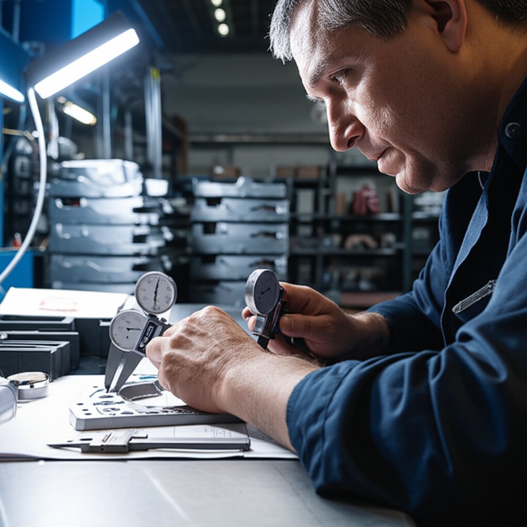
In-Process Checks and Final Verification
Quality stamping isn’t a one-and-done event—it’s a continuous process. Here’s how manufacturers keep every run of stamped sheet metal on target:
- Dimensional checks: Using calipers, micrometers, or coordinate measuring machines (CMM) to verify length, width, hole size, and position.
- Visual inspection: Looking for surface defects, scratches, dents, or missing features.
- Burr and edge assessment: Ensuring edges are free from sharp burrs or deformation that could affect fit or safety.
- Flatness and form checks: Confirming the part sits flat and that bends or forms meet the specified angles and radii.
- Surface finish and coating verification: Checking for uniform plating, paint, or protective coatings as required.
Advanced techniques, like optical vision systems or 3D scanning, provide fast, non-contact measurement of complex geometries—especially useful for high-volume or high-precision metal stamping parts. Functional gauges allow for rapid go/no-go checks right on the production floor, ensuring parts fit together as designed.
| Inspection Checklist for Stamped Parts |
|---|
|
Key insight: Consistent coil properties and well-maintained tooling are at the heart of repeatable quality. When you control your materials and your tools, you control your results.
Sampling Plans and Expanding the Control Plan
How often should you check your stamped metal components? Sampling plans are set based on production volume, part criticality, and industry standards. More frequent checks are typical for new launches, complex shapes, or safety-critical parts. As production stabilizes, statistical sampling ensures ongoing quality without excessive inspection costs.
Don’t forget: secondary operations such as tapping, welding, or assembly add new variables. Each step should have its own inspection criteria, expanding the overall control plan to cover every feature that matters to your application.
By integrating robust inspection methods and realistic tolerances, you’ll ensure your stamped sheet metal parts deliver the reliability, fit, and finish your customers expect. Up next, we’ll explore how these quality practices tie directly to cost and what you should know before sending out your next RFQ.
Stamping Costs and a Buyer RFQ Checklist
Ever wondered why two seemingly similar stamped parts can have very different price tags? Or why high volume metal stamping is so much more cost-effective than a short run? The answer lies in understanding the true cost drivers behind every stamped component. Whether you’re a design engineer or a procurement professional, knowing what really impacts cost will help you optimize designs, negotiate smarter, and avoid surprises down the line. Let’s break down the essentials of stamping and pressing costs—from initial tooling to the last piece off the line.
One-Time Tooling Versus Per-Part Costs
Imagine you’re launching a new product. The first big expense you’ll encounter is tooling: the custom dies required to produce your part shape. Tooling can be a significant investment, but it’s a one-time cost—amortized over the entire production run. For high volume metal stamping, this upfront spend quickly pays off, as the per-part cost drops with every additional piece made. In contrast, for low volume metal stamping or prototypes, tooling cost can dominate the total price per part, making alternative processes more attractive for very short runs.
Material Utilization and Nesting Strategy
Material is often the largest recurring cost in sheet metal stampings. The type, thickness, and grade of metal chosen all affect price, but so does how efficiently you use it. Smart nesting—arranging parts closely on the sheet or coil—minimizes scrap and maximizes yield. Complex shapes or inefficient layouts can lead to higher waste, driving up the cost per part. For production stamping, even a small improvement in yield can save thousands over a large run.
Setup, Changeover, and Volume Break-Evens
Each time a stamping press is set up for a new job, there are labor and machine costs—cleaning, loading dies, adjusting feeds, and running first-article checks. For custom metal stamping services, these setup costs are spread across the total order. That’s why high volume metal stamping has lower per-part costs: the fixed setup is diluted over thousands or millions of parts. Conversely, frequent changeovers or small batch runs mean higher costs per piece. The volume at which stamping becomes the most economical choice—the break-even point—depends on part complexity, tooling cost, and expected annual usage.
| Cost Driver | Effect on Tooling Cost | Effect on Per-Part Price | Optimization Tip |
|---|---|---|---|
| Tooling Complexity | High (more features/stations = higher cost) | Lower as volume increases | Simplify part design and minimize unique features |
| Material Type/Grade | Low | Direct impact (premium metals cost more) | Choose the least costly material that meets requirements |
| Material Yield/Nesting | None | High if scrap is excessive | Work with supplier to optimize part layout |
| Setup & Changeover | Low | Significant for small batches | Order larger batches or consolidate part numbers |
| Secondary Operations | May require extra tooling | Adds labor and time per part | Integrate features into stamping if possible |
| Tolerance & Surface Finish | High for tight specs | Higher inspection and scrap costs | Specify only what’s functionally necessary |
Buyer RFQ Checklist for Sheet Metal Stampings
Ready to request a quote for your next project? Here’s a practical checklist to ensure you get accurate and comparable pricing from suppliers. Copy and customize this list for your next RFQ:
- Complete part drawing with revision control
- Material specification (type, grade, thickness)
- Estimated annual and release volumes
- Critical tolerances and feature priorities
- Surface finish or coating requirements
- Packing, labeling, and delivery preferences
- Required PPAP or quality documentation level
- Target delivery dates and lead time expectations
- Any special certifications or compliance needs
Reminder: Early collaboration with your stamping and pressing partner during the design phase (DFM review) can dramatically reduce both tooling and per-part costs—helping you avoid costly changes or delays later on.
By understanding these cost drivers and preparing a thorough RFQ, you’ll set yourself up for a smoother sourcing process, competitive pricing, and successful metal stamping production. Next, we’ll help you compare stamping to other manufacturing methods—so you can make the best choice for your project’s needs.
When to Use Stamping Versus Forging or Machining for Automotive Parts
Choosing the right manufacturing process for your next automotive project can feel overwhelming. Should you use stamping, forging, or machining? The answer depends on your priorities—whether it’s strength, geometry complexity, volume, or time-to-market. Let’s break down the key differences, with a special focus on automotive metal stamping and its alternatives, so you can make an informed, cost-effective decision.
When Stamping Excels
Imagine you need thousands—or even millions—of brackets, covers, or stamped steel parts for a vehicle. The automotive metal stamping process shines when you need:
- High-volume production: Stamping is incredibly fast and repeatable, making it ideal for mass manufacturing.
- Complex but flat or shallow features: Intricate shapes, holes, and bends are easily achieved—think door panels, mounting tabs, or stamped aluminum parts for lightweight applications.
- Cost efficiency: Once tooling is built, the per-part cost drops dramatically at scale.
- Consistent quality: Tight tolerances and reliable repeatability are hallmarks of industrial metal stamping.
However, stamping does have its limits. Parts with deep draws, thick sections, or those needing maximum mechanical strength may push the process too far, requiring excessive secondary operations or risking premature failure in service.
When Forging Delivers Superior Strength
Ever wondered why critical load-bearing components—like crankshafts or suspension arms—are often forged instead of stamped? Forging uses compressive force to shape metal, aligning the grain structure and eliminating internal voids. This results in:
- Exceptional strength and fatigue resistance: Forged parts are ideal for high-stress, safety-critical automotive applications.
- Superior impact performance: The process produces components that withstand repeated shock and vibration far better than stamped or even machined parts.
- Best for thick, complex geometries: If your part’s cross-section is hefty or the geometry is not easily formed from sheet, forging is often the best fit.
Of course, forging comes with higher tooling costs and longer lead times, but for mission-critical strength, it’s often the only viable choice. For automotive projects demanding IATF 16949-certified quality and rapid scaling from prototype to mass production, consider an experienced partner like Shao-Yi Automotive Forging Parts. Their end-to-end solution, in-house die design, and global logistics support make them a trusted resource for over 30 automotive brands worldwide.
When Machining Is the Better Fit
Sometimes, neither stamping nor forging is the answer—especially when you need:
- Low-volume or prototype runs: Machining requires no dedicated tooling, so it’s ideal for small batches or design validation.
- Highly complex or precise geometries: Multi-axis CNC machining can create intricate shapes, tight tolerances, and features that stamping or forging can’t achieve without secondary operations.
- Hard-to-form materials: Some alloys are easier to cut than to form or press.
The trade-off? Machining is generally slower and more expensive per part at volume, but unbeatable for flexibility and precision in the right context.
Comparison Table: Stamping vs. Forging vs. Machining
| Criteria | Stamping | Forging | Machining |
|---|---|---|---|
| Mechanical Properties | Good (adequate for most body/chassis parts) | Excellent (best for high-load, safety-critical) | Good (depends on material, isotropic) |
| Geometry Complexity | High for 2.5D shapes, limited for thick/deep | Moderate (best for robust, thick sections) | Very high (3D, internal features possible) |
| Tooling Lead Time | Medium (weeks for dies) | Long (custom dies, heat treatment) | Short (minimal for prototypes) |
| Scalability | Excellent (ideal for mass production) | Good (best at high volumes) | Poor (slow, best for low volume) |
| Surface Finish | Good (may need deburring, coating) | Fair (often requires machining after forging) | Excellent (can achieve very fine finishes) |
| Per-Part Cost at Volume | Lowest (after tooling investment) | Moderate to high (tooling, material waste) | Highest (labor and cycle time intensive) |
Key takeaway: For high-volume, complex-but-shallow automotive parts, stamping is hard to beat. When strength, impact resistance, or thick cross-sections are critical, forging is the clear winner. Machining fills the gaps for prototypes, precision features, or challenging geometries. The best results come from matching your process to your project’s true requirements.
Next up, we’ll walk you through sourcing steps and trusted resources to help you turn your stamped or forged part concepts into reality—while keeping timelines and quality standards on track.
Sourcing Next Steps and Trusted Resources for Metal Stamping Projects
Ready to bring your stamped part concept to life, but unsure where to start? Whether you’re seeking high-volume production or a custom metal stamping solution, the right sourcing approach can make all the difference between a seamless launch and costly delays. Let’s walk through a practical roadmap and highlight essential resources to help you align with the best metal stamping companies for your needs.
Supplier Shortlist and Outreach Plan
Imagine you’ve finalized your design and are eager to get quotes. Where do you begin? Start by identifying a shortlist of reputable metal stamping manufacturers that match your part’s technical requirements, volume, and location preferences. Consider these steps:
- Define your needs: Clarify part geometry, material (e.g., stamped steel or aluminum), annual volume, and quality expectations.
- Research potential partners: Look for a metal stamping company with proven experience in your industry, the right certifications, and the ability to handle your project’s size and complexity. Use supplier interview checklists or resources from industry guides to vet their capabilities.
- Request and compare quotes: Send detailed RFQs to a select group of custom metal stamping suppliers—ideally three or more for a balanced comparison. Evaluate not just price, but also lead time, value-added services, and location impact on logistics (reference).
- Assess fit and responsiveness: Ask about their experience with similar parts, secondary operations, and design support. A strong metal stamper will be proactive in clarifying requirements and suggesting optimizations.
DFM and Risk Review Before Tooling
Before locking in a supplier or kicking off tooling, collaborate on a Design for Manufacturability (DFM) review. This step uncovers potential issues—such as tight tolerances, challenging features, or unclear specs—before they become costly problems. Leading custom metal stamping partners will help you:
- Validate that your design aligns with stamping process capabilities
- Identify opportunities to simplify features or reduce material waste
- Clarify quality and inspection expectations
- Plan for any secondary operations or finishing steps
Early DFM collaboration is key to reducing risk and ensuring a smooth transition from design to production.
Pilot Runs and Ramp to Volume
Once tooling is ready, a pilot or first-article run helps confirm that parts meet all requirements in real-world conditions. This is your opportunity to catch any last-minute issues and fine-tune the process before full-scale production. After successful validation, you can confidently ramp up to your target volumes, knowing your metal stamping manufacturer is ready to deliver consistent quality.
RFQ Documentation Checklist
To streamline quoting and avoid miscommunication, include these documents in your RFQ package:
- Complete part drawing (with revision and tolerances)
- Material specification and thickness
- Annual and batch volume estimates
- Critical features and inspection requirements
- Surface finish or coating needs
- Packing and delivery preferences
- Required certifications (e.g., IATF 16949, if automotive)
- Target delivery dates
Recommended Resources for Sourcing and Design
- Shao-Yi Automotive Forging Parts – For projects where a stamped design is revised to a forged geometry for added strength or weight optimization. Their IATF 16949-certified, end-to-end solution is ideal for automotive and strength-critical applications.
- Larson Tool & Stamping Resources – Access design guides, supplier interview checklists, and deep-draw stamping expertise for your next custom metal stamping project.
- IndustryStar Sourcing Guide – Practical advice on evaluating metal stamping companies and building a robust supply chain partnership.
- AMG Industries RFQ Guide – Step-by-step instructions for preparing and submitting effective RFQs for metal stamping manufacturers.
Takeaway: Early and open collaboration with your chosen metal stamping company—starting from DFM review through pilot validation—sets the stage for reliable, cost-effective production and on-time delivery. Don’t hesitate to leverage supplier expertise and industry resources to optimize both your part and your sourcing process.
Frequently Asked Questions About Metal Stamping
1. What are the four main types of metal stamping?
The primary metal stamping types are progressive die stamping, transfer die stamping, four-slide stamping, and deep draw stamping. Each type is suited for specific part shapes and production volumes, with progressive and transfer dies being most common for high-volume manufacturing.
2. Is metal stamping a difficult process to perform?
Metal stamping requires precise equipment and careful setup, but with the right tools and materials, it is highly repeatable and efficient. The process can be complex for intricate parts or hard metals, but modern presses and dies make it manageable for manufacturers.
3. How does metal stamping compare to other manufacturing methods like forging or machining?
Metal stamping is ideal for high-volume production of parts with complex but shallow features, offering speed and cost efficiency. Forging is chosen for parts needing superior strength and impact resistance, while machining is best for low-volume runs or highly complex shapes that stamping or forging can't achieve economically.
4. What factors influence the cost of metal stamping?
Key cost factors include tooling complexity, material type and yield, setup and changeover time, production volume, and any secondary operations. Higher volumes reduce per-part cost, while intricate designs or frequent changeovers can increase expenses.
5. What should be included in an RFQ for custom metal stamping?
A comprehensive RFQ should specify part drawings with revisions, material type and thickness, annual and batch volumes, critical tolerances, surface finish needs, packaging requirements, quality documentation (like PPAP), delivery timelines, and any required certifications.