 Small batches, high standards. Our rapid prototyping service makes validation faster and easier —

Steel Stamping Dies Exposed: Material Secrets Manufacturers Won't Share
Understanding Steel Stamping Dies in Modern Manufacturing
Ever wondered how manufacturers transform flat sheets of metal into precisely shaped automotive panels, electronic housings, or medical device components? The answer lies in steel stamping dies—precision-engineered tools that serve as the backbone of modern metal forming operations.
What Are Steel Stamping Dies and Why Do They Matter
Steel stamping dies are specialized tooling systems designed to cut, bend, shape, and form sheet metal into specific configurations with remarkable accuracy. According to The Phoenix Group, these precision tools consist of two halves placed inside a press capable of generating tremendous force to perform essential functions: locating, clamping, working, and releasing material.
Think of a standard die as a sophisticated mold system. The upper and lower components work together to impart exact shapes onto metal sheets, ensuring every produced part maintains identical specifications. This consistency is what makes die stamping indispensable for mass production environments where quality uniformity cannot be compromised.
The Foundation of Precision Metal Forming
What sets metal stamping dies apart from other forming methods? Their ability to execute multiple value-added operations in controlled sequences. These operations include:
- Cutting and piercing for material separation
- Bending and forming for dimensional shaping
- Drawing and stretching for complex geometries
- Embossing and coining for surface detailing
- Extruding for material displacement
Each stamping die is custom-designed based on final product specifications, incorporating advanced engineering techniques. Manufacturers typically construct these tools from hardened steel or carbide materials, ensuring durability for long-term, high-volume production runs.
"A stamping die is a precision tool that cuts and forms metals into functional shapes—value-added operations only occur during the working function of the die, making proper die design the single most critical factor in manufacturing success."
From Raw Steel to Finished Parts
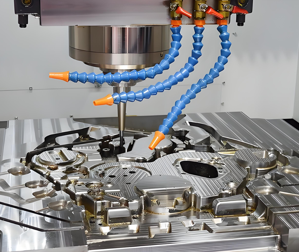
When you operate a steel stamp machine, the process appears straightforward: material enters, press cycles, finished parts emerge. However, beneath this simplicity lies sophisticated engineering that determines production efficiency, part quality, and ultimately, manufacturing profitability.
The critical investment in quality stamping dies pays dividends across multiple dimensions. High-quality tooling delivers consistent precision, reduces scrap rates, minimizes secondary operations, and extends production capabilities before maintenance interventions become necessary.
This article goes beyond introductory overviews and catalog-style specifications. You'll gain comprehensive technical guidance on die materials, advanced coatings, integration with automated systems, troubleshooting protocols, and ROI considerations that directly impact your manufacturing decisions. Whether you're evaluating new tooling investments or optimizing existing die performance, the insights ahead will bridge the gap between basic understanding and practical application.
Types of Stamping Dies and Their Applications
Selecting the right stamping die type can mean the difference between profitable production runs and costly manufacturing headaches. Each die category brings distinct advantages—and understanding these differences helps you match tooling investments to specific project requirements.
Let's break down the four major stamping die categories and explore when each delivers optimal results.
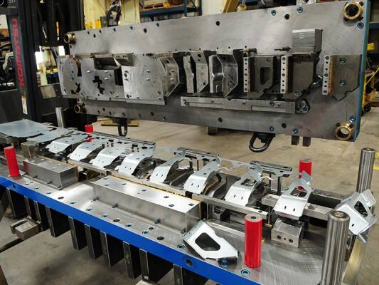
Progressive Dies for High-Volume Efficiency
Imagine an assembly line where each station performs a specialized task, with the workpiece automatically advancing from one operation to the next. That's precisely how a progressive die functions. According to Engineering Specialties Inc., progressive die stamping feeds a coil of metal through the stamping press, simultaneously punching, bending, and shaping parts while the workpiece remains attached to the base strip until the final separation step.
What makes progressive die manufacturing so attractive for high-volume applications? Several key advantages stand out:
- Exceptional speed for large production runs with strict tolerance specifications
- High repeatability that ensures consistent part quality across millions of cycles
- Reduced handling since parts remain connected throughout processing
- Cost efficiency that improves dramatically as production volumes increase
However, progressive dies require significant upfront tooling investment in permanent steel tooling. They're also less suitable for parts requiring deep drawing operations. Progressive die manufacturers typically recommend this approach for simpler to moderately complex geometries produced in quantities exceeding tens of thousands of units.
Common materials processed through progressive dies include steel, aluminum, copper, stainless steel, brass, and even specialty alloys like titanium and Inconel.
Transfer Dies and Complex Geometries
When your design requires intricate features like knurls, ribs, threading, or deep-draw characteristics, transfer die stamping becomes the preferred approach. Unlike progressive operations where parts stay attached to the metal strip, transfer stamping separates each part from the strip immediately, then mechanically transports it through multiple stations using specialized "fingers."
This fundamental difference opens possibilities that progressive dies simply cannot match. As noted by Worthy Hardware, transfer die stamping allows more flexibility in part handling and orientation, making it ideal for intricate designs and shapes that require specialized manipulation between operations.
Transfer stamping excels for:
- Tube applications and cylindrical components
- Deep-draw components where press depth exceeds strip-fed limitations
- Large parts that would be impractical in progressive die configurations
- Complex assemblies requiring multiple sequential operations with varied orientations
The trade-offs? Higher operational costs due to complex setups and skilled labor requirements. Longer setup times, particularly for intricate parts, can affect production timelines. Additionally, transfer dies demand greater precision in design and maintenance to ensure consistent quality.
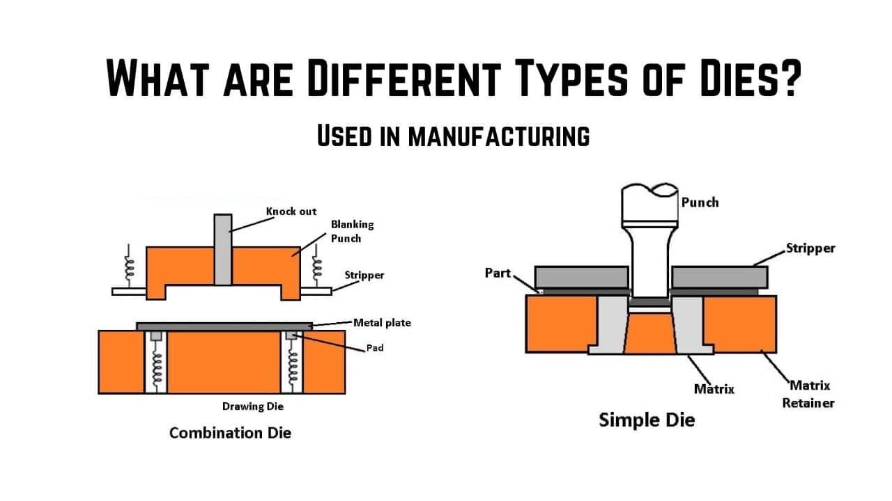
Compound vs Combination Dies Explained
Here's where terminology often creates confusion. Compound dies and combination dies serve different purposes, though both accomplish multiple operations in single press strokes.
A compound die performs multiple cutting operations simultaneously in one station during a single stroke. Picture creating a washer—the die punches the center hole while simultaneously blanking the outer diameter. This approach delivers exceptional flatness and concentricity since all cutting happens instantaneously without repositioning.
Key characteristics of compound stamping die configurations include:
- Superior precision for flat parts requiring tight tolerances
- Efficient material usage with minimal scrap
- Cost-effectiveness for medium to high-volume production of simpler geometries
- Speed advantages for small components that exit the die quickly
Combination dies, by contrast, integrate both cutting and forming operations within a single tool. A complete stamp die set might pierce holes, trim edges, and bend flanges all in one press cycle. This versatility makes combination dies valuable when parts require mixed operation types but don't justify the complexity of progressive tooling.
When evaluating die stamps for your application, consider that compound dies excel at precision cutting for flat parts, while combination dies handle mixed cutting and forming requirements. Neither matches progressive dies for complex multi-station work or transfer dies for intricate three-dimensional geometries.
Die Type Comparison at a Glance
Choosing the optimal stamping set requires balancing production volume, part complexity, and budget constraints. This comparison table summarizes key decision factors:
| Die Type | Best Applications | Production Volume Suitability | Complexity Level | Typical Industries |
|---|---|---|---|---|
| Progressive Die | Multi-operation parts with strict tolerances; components remaining flat or with moderate forming | High volume (50,000+ units); most cost-effective at scale | Simple to moderately complex geometries | Automotive, electronics, appliances, connectors |
| Transfer Die | Deep-draw components; tube applications; large parts; intricate 3D shapes with knurls, ribs, threading | Versatile for short and long runs; cost varies with complexity | High complexity with intricate design elements | Automotive structural, aerospace, heavy equipment, medical devices |
| Compound Die | Flat parts requiring simultaneous cutting operations; washers, blanks, simple shapes needing tight concentricity | Medium to high volume; excellent precision at speed | Simple—limited to cutting operations only | Fasteners, gaskets, electrical components, precision blanks |
| Combination Die | Parts needing mixed cutting and forming in single stroke; moderate complexity without multi-station requirements | Medium volume; balances tooling cost with operational efficiency | Moderate—handles cutting and forming but not extensive sequences | Consumer products, hardware, general manufacturing |
Understanding these precision die and stamping categories helps you communicate effectively with tooling partners and make informed decisions about stamping die components that match your production requirements. The right choice depends on your specific combination of volume targets, geometric complexity, and budget parameters.
Of course, selecting the appropriate die type represents only part of the equation. The materials used to construct these tools—and the advanced treatments applied to their surfaces—determine how long your investment performs before requiring maintenance or replacement.
Die Materials and Steel Grade Selection
Here's a truth most tooling catalogs won't tell you: the steel grade inside your stamping die determines whether you'll achieve millions of trouble-free cycles or face premature failure after just thousands. Understanding material science separates manufacturers who make informed investments from those who gamble on the cheapest option—and lose.
When designing sheet metal stamping dies, material selection directly impacts hardness, wear resistance, toughness, and ultimately, your cost per part. Let's explore the steel grades that professionals specify for demanding metal stamping die design applications.
Tool Steel Grades for Die Construction
Tool steels aren't created equal. Each grade represents a carefully engineered balance of properties tailored to specific operating conditions. According to SteelPro Group, genuine tool steels maintain high hardness, strength, and wear resistance even under extreme mechanical stress—characteristics essential for stamping applications.
Four steel grades dominate professional sheet metal dies construction:
D2 Tool Steel
- Carbon content: 1.4-1.6% with high chromium (11-13%)
- Hardness: Achieves 58-62 HRC after heat treatment
- Primary strength: Superior wear resistance for abrasive materials
- Best applications: Blanking punches, cutting edges, high-wear stamping die design scenarios
- Trade-off: Higher brittleness compared to lower-alloy grades
D2 excels when processing abrasive materials like high-strength steels or stainless alloys. Its high chromium content creates hard carbides throughout the matrix, delivering exceptional edge retention. However, this same characteristic makes D2 more susceptible to chipping under impact loading.
A2 Tool Steel
- Carbon content: 0.95-1.05% with moderate chromium (4.75-5.5%)
- Hardness: Typically 57-62 HRC
- Primary strength: Excellent dimensional stability during heat treatment
- Best applications: Complex metal punch and die configurations requiring tight tolerances
- Trade-off: Lower wear resistance than D2
A2's air-hardening characteristic minimizes distortion during heat treatment—a critical advantage for intricate die geometries. When your metal stamping die sets require precision features that cannot tolerate warping, A2 often becomes the preferred choice.
S7 Tool Steel
- Carbon content: 0.45-0.55% with chromium and molybdenum
- Hardness: 54-58 HRC typical working range
- Primary strength: Exceptional shock resistance and toughness
- Best applications: Forming operations, impact-intensive stamping, metal die punch components subject to sudden loads
- Trade-off: Lower hardness limits wear resistance
When your dies experience repetitive impact forces, S7 absorbs shock without cracking. This makes it invaluable for forming operations where the die contacts material aggressively rather than simply cutting through it.
M2 High-Speed Steel
- Composition: Tungsten (6%), molybdenum (5%), vanadium (2%)
- Hardness: 60-65 HRC achievable
- Primary strength: Retains hardness at elevated temperatures
- Best applications: High-speed production, operations generating significant heat
- Trade-off: More challenging to machine and grind
M2 maintains cutting performance even when friction generates substantial heat—a property called hot hardness. For high-cycle production where thermal buildup degrades conventional steels, M2 extends intervals between sharpening or replacement.
When to Specify Carbide Components
Sometimes even premium tool steels fall short. Carbide inserts—typically tungsten carbide with cobalt binders—offer hardness exceeding 1400 HV, far surpassing any steel grade. As referenced in Jeelix's material selection guide, cemented carbides stand at the top in terms of hardness and compressive strength.
Consider carbide components when:
- Processing highly abrasive materials that quickly erode steel edges
- Production volumes exceed hundreds of thousands of cycles
- Dimensional tolerances demand extended edge stability
- Secondary finishing operations must be eliminated
The economics favor carbide when total cost of ownership matters more than initial tooling expense. A carbide insert costing three times more than its steel equivalent but lasting ten times longer delivers significant per-part savings.
Modern metal stamping die sets often combine steel die bodies with strategically placed carbide inserts at high-wear locations. This modular approach optimizes cost while concentrating premium materials where they provide maximum benefit.
Matching Die Materials to Production Demands
Material selection isn't a simple specification—it's a strategic decision balancing multiple competing factors. The performance triangle concept described by material scientists involves three interconnected properties: hardness, toughness, and wear resistance. Maximizing one typically compromises another.
For sheet metal stamping dies, match your material choice to these operational realities:
Workpiece Material Characteristics
Soft aluminum requires different die properties than hardened stainless steel. Abrasive materials demand high wear resistance (D2, carbide). Work-hardening alloys need tougher dies (S7, A2) that resist the increased forces generated as material strengthens during forming.
Production Volume Requirements
Short runs tolerate economical materials with faster replacement cycles. High-volume production justifies premium grades and carbide components that minimize interruptions for maintenance or die changes.
Heat Treatment Considerations
Proper heat treatment unlocks a steel's potential—or destroys it. Each grade requires specific austenitizing temperatures, quenching media, and tempering cycles. Incorrect heat treatment causes:
- Insufficient hardness leaving edges that deform under load
- Excessive brittleness leading to cracking and chipping
- Distortion requiring costly rework or complete replacement
- Residual stresses that cause premature fatigue failure
Partner with heat treatment specialists who understand tool steel metallurgy. A perfectly specified D2 die improperly hardened performs worse than correctly treated A2.
Preventing Premature Die Failure
Die failures rarely happen randomly. They result from mismatches between material capabilities and operational demands. Common failure modes and their material-related causes include:
- Edge chipping: Material too hard and brittle for impact loads (specify S7 instead of D2)
- Rapid wear: Insufficient hardness or wear resistance for workpiece abrasiveness (upgrade to carbide inserts)
- Cracking: Inadequate toughness combined with improper heat treatment
- Galling: Material adhesion from poor surface finish or incompatible die/workpiece pairing
Understanding these steel grades and their applications gives you vocabulary to communicate precisely with die manufacturers. But material selection represents only the foundation—advanced surface treatments can multiply your die's performance several times over.
Advanced Coatings and Surface Treatments for Extended Tool Life
You've selected the right steel grade for your stamper dies. You've partnered with a qualified heat treatment specialist. Yet within months, you're facing premature wear, material pickup, and declining part quality. What went wrong?
The missing element is often surface treatment. Modern coatings transform good steel stamping tools into exceptional performers—multiplying tool life by factors of three to ten while enabling production speeds that would destroy uncoated surfaces. Let's explore the coating technologies that separate average die performance from industry-leading results.
Surface Coatings That Multiply Die Life
Why do coatings matter so much? Every time your die stamp contacts sheet metal, microscopic interactions occur at the surface. Friction generates heat. Metal transfers between surfaces. Edges degrade imperceptibly with each cycle—until degradation becomes visible quality problems.
Coatings interrupt this destructive cycle through three mechanisms:
- Hardness enhancement: Coating layers exceed substrate hardness by 2-4 times, resisting abrasive wear
- Friction reduction: Lower coefficients of friction decrease heat generation and material adhesion
- Barrier protection: Physical separation prevents direct metal-to-metal contact between die and workpiece
According to SPS Unmold's coating analysis, these benefits translate directly to reduced downtime, fewer changeovers, and lower maintenance costs. The result? Your stamp die investment delivers returns across many more production cycles.
Four coating families dominate professional stamping applications. Each offers distinct advantages depending on your workpiece material, production volume, and operating conditions.
Titanium Nitride (TiN)
- Hardness: Approximately 2,300 HV
- Friction coefficient: 0.4-0.6 against steel
- Maximum operating temperature: 600°C
- Appearance: Distinctive gold color
- Best applications: General-purpose wear protection for mild steel and aluminum stamping
TiN remains the industry workhorse—affordable, well-understood, and effective for moderate-demand applications. Its gold coloring also provides visual wear indication, showing when coating has worn through to substrate.
Titanium Carbonitride (TiCN)
- Hardness: 3,000-3,500 HV
- Friction coefficient: 0.3-0.4 against steel
- Maximum operating temperature: 450°C
- Appearance: Blue-gray metallic
- Best applications: Abrasive materials, stainless steel forming, enhanced lubricity requirements
When processing work-hardening materials or abrasive alloys, TiCN's higher hardness and improved lubricity outperform standard TiN. The carbon addition creates a coating particularly effective against adhesive wear mechanisms.
Titanium Aluminum Nitride (TiAlN)
- Hardness: 3,400-3,600 HV
- Friction coefficient: 0.5-0.7 (dry conditions)
- Maximum operating temperature: 900°C
- Appearance: Dark violet to black
- Best applications: High-temperature operations, high-speed production, hard metal stamping
Research published in Wear journal confirms TiAlN's exceptional high-temperature stability. The aluminum content forms a protective Al₂O₃ layer during operation, actually improving wear resistance as temperatures increase. For steel stamper operations running at elevated speeds, TiAlN maintains performance where other coatings fail.
Diamond-Like Carbon (DLC)
- Hardness: 2,000-8,000 HV (depending on formulation)
- Friction coefficient: 0.05-0.20
- Maximum operating temperature: 350°C
- Appearance: Black, mirror-like finish
- Best applications: Dry stamping, aluminum forming, applications requiring minimal lubricant
DLC coatings deliver the lowest friction coefficients available—sometimes approaching that of graphite. According to the ScienceDirect research, DLC/TiAlN multilayer configurations show high potential as protective coatings, combining TiAlN's thermal stability with DLC's exceptional lubricity. This makes DLC particularly valuable for dry or minimally lubricated punch stamp operations.
Coating Selection by Material and Volume
Choosing the optimal coating requires matching surface treatment properties to your specific production environment. Consider these decision factors:
Workpiece Material Compatibility
Softer metals like aluminum benefit most from DLC's extremely low friction, which prevents material pickup and galling. Harder steels and stainless alloys demand TiCN or TiAlN's superior abrasion resistance. As noted by 3ERP's galling prevention guide, coating selection directly impacts whether workpiece material adheres to die surfaces—a primary cause of quality problems and premature die failure.
Production Speed Requirements
Higher stroke rates generate more friction and heat. TiAlN excels in high-speed environments because its thermal stability actually improves at elevated temperatures. DLC performs excellently for high-speed work but requires attention to temperature limits—exceeding 350°C degrades the coating structure.
Lubrication Strategy
Moving toward dry or near-dry stamping? DLC becomes nearly essential. Traditional coatings like TiN assume lubricant presence and struggle without it. The friction coefficient difference between lubricated TiN (0.4) and dry DLC (0.1) translates directly to reduced forming forces, lower heat generation, and extended die life.
Multilayer Configurations
Modern coating technology increasingly combines materials in layered structures. DLC over TiAlN creates a surface combining thermal stability with minimum friction. These multilayer approaches outperform single coatings by addressing multiple wear mechanisms simultaneously.
The Economics of Die Surface Treatment
Surface treatment adds cost—typically 15-30% of base die expense for quality PVD coatings. Is this investment justified? The economics become compelling when you calculate total cost of ownership rather than initial tooling expense.
Consider a production scenario comparing coated versus uncoated steel stamping tools:
- Uncoated die: 50,000 cycles before regrinding required
- TiN-coated die: 150,000-200,000 cycles before regrinding
- DLC-coated die: 250,000-500,000 cycles depending on application
The coating investment recovers quickly through:
- Reduced downtime: Fewer die changes mean more productive press hours
- Lower maintenance costs: Extended intervals between regrinding and refurbishment
- Improved quality: Consistent surface finish throughout longer production runs
- Higher speeds: Reduced friction enables faster cycle times without overheating
Maintenance scheduling also shifts with coated dies. Instead of reactive responses to quality problems, manufacturers can plan predictable refurbishment intervals. This predictability reduces emergency downtime and allows better production planning.
The relationship between coating selection and overall die ROI is straightforward: properly matched coatings multiply the productive cycles your tooling investment delivers. A die lasting three times longer effectively costs one-third as much per part produced.
Of course, even the best-coated dies require integration with modern manufacturing systems to realize their full potential. The next frontier in die performance involves connecting these precision tools with automated press lines and intelligent sensing systems.
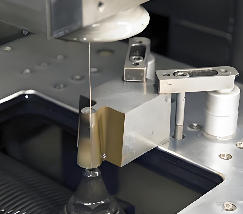
CNC Integration and CAE Simulation in Die Development
What happens when your perfectly engineered manufacturing die meets a press line that can't communicate with it? Wasted potential. Modern steel stamping dies represent only half the performance equation—the other half depends on how seamlessly these tools integrate with automated systems, sensors, and simulation software that optimize every production cycle.
The gap between traditional die-making and Industry 4.0 manufacturing is closing rapidly. Understanding this integration transforms how you specify tooling and evaluate supplier capabilities.
Integrating Dies with Automated Press Lines
Today's automotive stamping dies don't operate in isolation. They function as components within sophisticated automated systems where every element communicates, adjusts, and responds in real time. According to Keysight's analysis of stamping processes, the key components work in unison—press machines, die sets, material feeding systems, blank holders, cushion systems, and ejection mechanisms—to ensure smooth, efficient, and precise stamping operations.
Different press technologies interface with dies in distinct ways:
- Servo presses: Programmable motion profiles with variable speed and stroke enable unprecedented control over die stamped part quality
- Transfer presses: Mechanical "fingers" transport parts through multiple stations, requiring dies designed for precise handoff positioning
- Progressive presses: Continuous strip feeding demands dies engineered for consistent material advancement and timing synchronization
The choice of press technology directly influences die design requirements. Servo presses, increasingly popular for automotive stamping die applications, offer flexibility that mechanical presses cannot match. Their programmable motion allows slower approach speeds near material contact, reducing impact forces on custom metal stamping dies while maintaining high overall cycle rates.
Robotic handling adds another integration layer. Modern production lines use robots for blank loading, part extraction, and inter-press transfer. Dies must incorporate features enabling reliable robotic interaction—consistent part positioning, adequate clearance for gripper access, and surface characteristics that prevent vacuum cup slippage.
Sensor Technology in Modern Die Systems
Imagine knowing a quality problem is developing before the first defective part reaches inspection. In-die sensing technology makes this possible by monitoring critical parameters throughout every press cycle.
Today's intelligent dies incorporate multiple sensor types:
- Force sensors: Detect variations in forming pressure that indicate material inconsistencies or tooling wear
- Displacement sensors: Monitor punch travel and material flow for dimensional accuracy verification
- Temperature sensors: Track thermal conditions affecting lubrication effectiveness and material behavior
- Acoustic sensors: Identify unusual sounds signaling tool damage or improper material feeding
This sensor data feeds into press control systems, enabling automatic adjustments that maintain quality without operator intervention. When force signatures deviate from established baselines, the system can modify blank holder pressure, adjust stroke parameters, or flag the condition for maintenance review.
For operations pursuing ITD precision stampings quality levels, sensor integration represents a competitive necessity rather than an optional upgrade. The data generated also supports predictive maintenance—identifying wear patterns before they cause production problems.
CAE Simulation for Defect Prevention
Here's where modern die development diverges most dramatically from traditional approaches. Computer-Aided Engineering simulation now predicts how sheet metal will behave during forming—before any physical die construction begins.
According to Keysight's research on virtual die try-outs, simulation addresses several critical challenges:
- Springback prediction: Advanced high-strength steels and aluminum alloys exhibit significant springback, making dimensional accuracy difficult without simulation-guided compensation
- Material flow analysis: Simulation reveals how metal moves during forming, identifying potential thinning, wrinkling, or splitting before physical trials
- Process optimization: Parameters like press speed, blank holder force, and lubrication can be fine-tuned virtually, reducing physical testing iterations
The economics are compelling. AutoForm's innovation timeline documents how simulation evolved from requiring two days for basic analysis (1995) to delivering validated die face designs in half a day rather than a week (2000). Today's software enables comprehensive process planning that simultaneously considers function, quality, lead time, and cost.
What makes simulation particularly valuable for automotive stamping die development? Defects in visible components—hoods, doors, fenders—often emerge only during physical try-out stages. By that point, corrections become time-consuming and costly. Simulation identifies aesthetic quality issues during design, when changes cost virtually nothing.
Digital Twin Technology
The digital twin concept extends simulation beyond initial design into ongoing production optimization. A digital twin mirrors the physical die's behavior, continuously updated with real-world production data. This enables:
- Virtual testing of process parameter changes before physical implementation
- Wear modeling that predicts maintenance requirements based on actual production history
- Quality correlation linking simulation predictions to measured part characteristics
As noted in AutoForm's 2021 innovations, single software platforms now allow full digitalization with seamless information and data flow—the practical implementation of Industry 4.0 principles in die-making.
Reducing Prototyping Iterations
Traditional die development followed an iterative pattern: design, build prototype, test, identify problems, modify, retest. Each physical iteration consumed weeks and significant expense. Simulation compresses this cycle dramatically.
Modern workflows simulate hundreds of design variations virtually, identifying optimal configurations before cutting any steel. The physical prototype becomes verification rather than exploration—confirming what simulation already predicted rather than discovering problems for the first time.
For custom metal stamping dies serving automotive applications, this approach delivers multiple benefits: faster time-to-production, lower development costs, and higher first-attempt success rates. Manufacturers achieving 90%+ first-pass approval rates typically leverage advanced simulation throughout their design process.
Understanding these integration technologies helps you evaluate die suppliers more effectively. The conversation shifts from simply "can you build this die?" to "how will this die perform within our automated production environment?" That distinction often separates adequate tooling from exceptional manufacturing outcomes.
Yet even the most sophisticated dies eventually encounter problems. Knowing how to diagnose issues and implement solutions keeps your production running—which brings us to practical troubleshooting guidance.
Troubleshooting Common Die Problems and Maintenance Solutions
Your steel stamping dies are running—until suddenly they're not. Production halts. Scrap rates climb. Quality complaints arrive from downstream processes. Sound familiar? Every stamping operation eventually confronts die problems, but how you respond determines whether issues become minor interruptions or major production crises.
The difference between reactive firefighting and proactive problem-solving comes down to understanding root causes. Let's examine the most common dies and stamping challenges, their underlying causes, and proven solutions that restore production quality.
Diagnosing Burr and Edge Quality Issues
Burrs represent perhaps the most frequent complaint in die and stamping operations. Those raised edges on stamped parts create downstream problems—assembly difficulties, safety hazards, and cosmetic defects that trigger customer rejections.
What causes burr formation? According to DGMF Mold Clamps' troubleshooting analysis, several factors contribute:
- Improper clearance: When punch-to-die clearance exceeds optimal ranges, material tears rather than shears cleanly
- Dull cutting edges: Worn edges require more force and produce ragged cuts
- Misalignment: Uneven clearance around the cutting perimeter creates burrs on one side while the opposite side appears acceptable
- Material variations: Harder or thicker material than specified increases burr tendency
Edge quality problems often appear gradually. Parts that passed inspection last month suddenly show unacceptable burrs. This progressive degradation typically signals cutting edge wear—the stamp and die surfaces that seemed sharp enough yesterday have crossed the threshold where they no longer produce clean cuts.
The solution depends on root cause identification. Alignment issues require checking the machine tool turret and mold mounting seat positions. As the reference material notes, regularly using alignment mandrels to check and adjust turret alignment prevents uneven wear patterns that cause one-sided burring.
Solving Dimensional Accuracy Problems
When parts drift out of tolerance, the consequences cascade through your manufacturing process. Assemblies don't fit. Functional requirements fail. Customers reject shipments.
Dimensional drift typically stems from three sources:
Thermal Effects
As machining dies heat during production, thermal expansion alters critical dimensions. Parts produced during morning startup may differ measurably from afternoon production. Temperature monitoring and allowing adequate warm-up periods before quality-critical runs helps stabilize dimensions.
Progressive Wear
Cutting edges and forming surfaces wear continuously. This wear follows predictable patterns—monitoring dimension trends through SPC charting reveals when adjustments become necessary before parts exceed tolerance limits.
Material Springback
Formed parts want to return toward their flat state. When springback compensation in the die no longer matches actual material behavior—perhaps due to supplier changes or material lot variations—formed dimensions drift.
The NADCA Die Care and Maintenance guide emphasizes that quality of castings directly correlates with die condition. Their grading system shows how "fair" tooling condition leads to noticeable parting line deterioration and dimensional challenges requiring secondary operations to sustain production.
Preventing Premature Die Wear
Every stamp dies eventually wears—but premature wear wastes your tooling investment. Understanding wear mechanisms helps you extend service life and schedule maintenance proactively rather than reactively.
Common causes of accelerated wear include:
- Inadequate lubrication: Metal-to-metal contact accelerates surface degradation exponentially
- Excessive tonnage: Running dies at pressures beyond design limits accelerates wear on all contact surfaces
- Material hardness: Processing materials harder than specified rapidly degrades cutting edges
- Contamination: Metal chips, debris, and lubricant breakdown products create abrasive conditions
- Thermal cycling: Repeated heating and cooling causes stress fatigue at the surface
The NADCA guidelines recommend stress relieving die cavities every 20,000 to 30,000 shots—a maintenance step many operations skip until problems appear. This periodic treatment relieves accumulated stresses before they manifest as cracking or accelerated wear.
According to Lime City Manufacturing's maintenance guidance, implementing a consistent die maintenance and repair schedule improves part quality and consistency, extends tool lifespan, minimizes unplanned downtime, and reduces long-term costs. Their approach emphasizes that proactive maintenance protects quality—the alternative is waiting until problems force expensive reactive repairs.
Common Die Problems Quick Reference
When production problems emerge, quick diagnosis matters. This troubleshooting table summarizes frequent stamping tooling issues with their likely causes and recommended solutions:
| Problem | Likely Causes | Recommended Solutions |
|---|---|---|
| Excessive burrs on cut edges | Worn cutting edges; improper punch-die clearance; misalignment between upper and lower tooling | Sharpen or replace cutting components; adjust clearance to 5-10% of material thickness; use alignment mandrel to verify turret positioning |
| Dimensional drift over production run | Thermal expansion during operation; progressive edge wear; material springback variations | Allow warm-up period before critical runs; implement SPC monitoring; verify incoming material properties match specifications |
| Uneven wear patterns | Machine turret misalignment; guide bushing wear; improper die clearance on one side | Check and adjust turret alignment regularly; replace worn guide bushings; adopt full guiding range die configuration |
| Material cracking during forming | Excessive forming severity; insufficient lubrication; material properties outside specification; sharp die radii | Reduce forming depth per operation; improve lubricant application; verify material certification; increase die radii where design permits |
| Galling and material pickup | Inadequate surface finish; improper coating selection; insufficient lubrication; incompatible die-workpiece material pairing | Polish die surfaces; apply appropriate coating (DLC for aluminum); increase lubricant coverage; consider material compatibility |
| Premature die cracking | Improper heat treatment; inadequate stress relieving; excessive impact loading; thermal fatigue from cycling | Verify heat treatment certification; stress relieve every 20,000-30,000 shots; review material selection for toughness; improve thermal management |
| Parts sticking in die | Insufficient draft angles; inadequate ejection force; surface finish too rough; lubricant breakdown | Increase draft where possible; add or strengthen ejection pins; polish surfaces; review lubricant selection and application |
| Flash at parting line | Worn or damaged parting surfaces; insufficient clamp tonnage; debris on parting surfaces; thermal expansion | Inspect and repair parting line surfaces; verify machine tonnage adequacy; clean parting surfaces between runs; monitor die temperature |
Regrinding Versus Replacement Decisions
When cutting edges wear, you face a choice: regrind to restore sharpness or replace the component entirely. This decision significantly impacts both cost and quality outcomes.
Regrinding makes sense when:
- Wear is limited to cutting edges without affecting overall geometry
- Sufficient material remains for removal while maintaining dimensional requirements
- Heat treatment integrity remains intact throughout the component
- Cost of regrinding plus production interruption is less than replacement
Replacement becomes necessary when:
- Cracking extends beyond surface level into the component body
- Multiple regrinds have consumed available material
- Dimensional requirements can no longer be met after grinding
- Heat checking or thermal damage has compromised metallurgical properties
The NADCA grading system provides useful benchmarks. "Fair" condition tooling—showing wear, wash, minor heat checking, and requiring polishing—typically warrants repair and continued use. "Poor" condition—with heavy wash, heat checking, and cracks extending into coolant lines—signals that major repairs or replacement become necessary.
Tracking regrind history for each die component helps predict end-of-life. Most cutting components tolerate three to five regrinds before dimensional constraints or metallurgical degradation mandate replacement.
Maintenance Scheduling and Inspection Protocols
Reactive maintenance—waiting until problems force action—costs more than prevention. Establishing systematic inspection and maintenance protocols extends die service life while reducing unplanned downtime.
The NADCA preventive maintenance program recommends these scheduled activities:
- After every run: Completely tear down the die and inspect all components; polish where required; replace worn or broken pins; lubricate ejector assembly
- Every 20,000-30,000 shots: Stress relieve cavities at 950°F for four hours; verify steel hardness; inspect and correct slides, cam pins, and locking heels
- Annually (for low-volume dies): Full stress relief and inspection regardless of shot count
Additional inspection protocols that prevent problems include:
- Draw polish all cavity surfaces to remove micro-cracks before they propagate
- Remove metal buildup from holding frames and inspect for damage
- Clean and polish gas vents to maintain proper air evacuation
- Flush water lines to remove lime buildup affecting thermal management
- Coat die faces with protective coating during storage to prevent rust
Documentation matters as much as the maintenance itself. Keeping detailed records of each maintenance activity, welding repair, component replacement, and stress relief treatment creates a history that reveals patterns and predicts future needs. When building replacement cavities, reviewing this history highlights improvement opportunities.
"Die condition has a direct relationship to casting quality. Excellent tooling produces excellent parts; poor tooling produces parts requiring secondary operations that erode profitability."
Effective troubleshooting and maintenance represent operational competencies—skills your team develops through experience and systematic approaches. But these capabilities only deliver value when the underlying die investment makes economic sense. Understanding the true costs and returns of stamping tooling helps you make decisions that optimize manufacturing profitability.
Cost Analysis and ROI Considerations for Die Investment
How much should you actually spend on a metal stamping die? Ask ten manufacturers and you'll get ten different answers—because the real question isn't about initial price. It's about total cost of ownership across your production lifecycle.
Most purchasing decisions focus narrowly on upfront tooling expense. This approach misses the larger picture: a die costing 30% more initially but lasting three times longer delivers dramatically better economics. Understanding what drives die costs—and how those costs translate into per-part expenses—separates manufacturers who optimize profitability from those who chase false savings.
Calculating True Die Investment Costs
Die pricing isn't arbitrary. Specific factors combine to determine what you'll pay for custom metal stamping tooling, and understanding these variables helps you evaluate quotes intelligently rather than simply accepting the lowest bid.
Key cost factors manufacturers should evaluate include:
- Design complexity: Multi-station progressive dies cost significantly more than simple blanking tools—more stations mean more precision components, tighter tolerances, and extended engineering time
- Material selection: D2 tool steel costs more than A2; carbide inserts add substantially to base pricing but may deliver superior long-term value
- Tolerance requirements: Tighter tolerances demand more precise machining, additional inspection steps, and higher-grade materials
- Part geometry: Deep draws, intricate features, and close-proximity piercing increase die construction difficulty
- Size and tonnage requirements: Larger dies require more material, heavier handling equipment, and bigger presses
- Surface treatment specifications: Advanced coatings like TiAlN or DLC add 15-30% to base die cost but multiply service life
- Lead time constraints: Expedited delivery commands premium pricing
According to Partzcore's analysis, optimizing material selection and simplifying designs where possible helps balance performance with cost-effectiveness. Collaboration with experienced suppliers often reveals cost-saving measures invisible to purchasers unfamiliar with dies manufacturing realities.
Beyond construction costs, factor in these frequently overlooked expenses:
- Engineering and design: CAE simulation, prototyping iterations, and design validation
- Tryout and qualification: Initial runs, adjustments, and first-article inspection
- Shipping and installation: Heavy tooling requires specialized transport and rigging
- Training: Operator familiarization with new die characteristics
- Spare components: Critical replacement parts kept in inventory
When comparing custom metal stamping services quotes, ensure you're evaluating equivalent scope. A seemingly lower price might exclude engineering support, tryout assistance, or warranty coverage that higher-priced competitors include.
Volume Thresholds That Justify Die Complexity
Here's the fundamental equation: more sophisticated dies cost more upfront but typically reduce per-part costs at volume. The question becomes—at what volume does increased die complexity pay for itself?
Consider this simplified comparison for a hypothetical part:
- Simple single-station die: $15,000 tooling cost, $0.50 per part including secondary operations
- Progressive die: $75,000 tooling cost, $0.12 per part with no secondary operations needed
The breakeven point? Approximately 158,000 parts. Below that volume, the simpler die delivers better economics despite higher per-part costs. Above that threshold, the progressive die's efficiency advantages compound with every additional unit.
As noted in OAE's cost-volume analysis, this type of analysis becomes essential for maintaining financial control and competitive advantage. The framework divides total costs into fixed costs (die investment) and variable costs (per-part expenses), examining how each responds to changes in project volume.
Volume thresholds shift based on several variables:
- Secondary operation costs: If simpler dies require expensive finishing, deburring, or assembly operations, breakeven points drop
- Scrap rates: Higher-quality dies typically produce fewer defective parts, reducing material waste
- Cycle time differences: Progressive dies running at 60 strokes per minute versus single-station dies at 20 dramatically affect labor costs per part
- Setup frequency: Multiple-part-number production requiring frequent changeovers favors flexible tooling over optimized single-purpose dies
For custom metal stampings serving automotive applications, volume projections often exceed breakeven thresholds significantly. When you're producing 500,000 units annually over a five-year program, even modest per-part savings translate to substantial total value.
Long-Term ROI of Quality Tooling
The true measure of die investment isn't what you paid—it's what you received in return. According to Palomar Technologies' ROI analysis, justification must ultimately meet overall company goals: increased sales, increased revenue, reduced production times, or increased market share.
Quality tooling affects ROI through multiple pathways:
Scrap Rate Reduction
Premium dies produce more consistent parts. When your custom metal stamping die maintains tighter tolerances throughout its service life, fewer parts fail inspection. A 2% reduction in scrap rate on a million-part run represents 20,000 additional saleable units—often worth more than the die cost difference itself.
Secondary Operation Elimination
Well-designed dies often eliminate downstream processing. If a higher-quality metal stamping die produces parts requiring no deburring, straightening, or rework, the savings accumulate with every cycle. Calculate what you spend annually on secondary operations—that figure often justifies significant tooling upgrades.
Downtime Reduction
Every hour your press sits idle waiting for die repairs represents lost revenue. Premium materials, proper coatings, and quality construction extend mean time between failures. As the Palomar analysis notes, automation can operate 24/7 where multiple personnel would be needed in manual operations—but only if tooling reliability supports continuous production.
First-Time Yield Improvements
The concept of first-time yield (FTY) captures whether parts meet specifications without rework. According to Palomar's analysis, if existing processes provide only 70% yield and improved tooling can deliver 99% yield, this alone could justify the investment over a few years. Accuracy and repeatability become major contributors to yield improvement.
Extended Service Life
A die lasting 500,000 cycles versus one failing at 150,000 effectively costs one-third as much per part produced—even if the initial investment was higher. When evaluating quotes, request expected service life estimates and factor these projections into your total cost calculations.
For payback period calculations, determine how many production hours (or parts) are required to recover the die investment. If your company policy requires capital equipment payback within three years, ensure projected volumes support that timeline before committing to expensive tooling.
The relationship becomes clear: upfront die investment and per-part costs are inversely related at scale. Manufacturers who optimize this relationship—investing appropriately based on realistic volume projections—consistently outperform competitors who purchase solely on initial price.
Understanding these economics prepares you for productive conversations with die suppliers. But knowing what to pay matters less than knowing who to pay—selecting the right manufacturing partner determines whether your tooling investment delivers expected returns or disappoints.
Selecting the Right Stamping Die Manufacturer
You've defined your die requirements, understood material options, and calculated your investment thresholds. Now comes the decision that ultimately determines whether those specifications become reality: choosing your stamping die manufacturers partner.
This selection process extends far beyond requesting quotes and comparing prices. The right supplier becomes a strategic asset—delivering tooling that performs as designed, supporting your production ramp-up, and responding when problems inevitably arise. The wrong choice? Delays, quality issues, and frustration that consume far more than any initial cost savings.
How do you distinguish capable stamping dies manufacturer candidates from those who'll underdeliver? Let's examine the evaluation criteria that matter most.
Evaluating Die Manufacturer Capabilities
When you're evaluating metal stamping die manufacturers, look beyond surface-level marketing claims. According to Penn United's supplier evaluation guide, making a purchasing decision only based on quoted cost may result in overall dissatisfaction with a supplier's performance—or even a disastrous situation.
Their research identifies ten critical factors that separate qualified suppliers from risky choices. Applying these criteria to stamping tool and die selection reveals what truly matters:
- Years of experience: Understand how long a supplier has operated and what types of components they've produced. Experience with your specific part complexity and material types matters more than general industry tenure.
- In-house die design capability: A manufacturer who designs precision stamping dies understands critical features and stations that maximize efficiency and quality during production. This integrated knowledge proves invaluable during troubleshooting.
- Die building and troubleshooting expertise: Suppliers who build their own tooling can diagnose and resolve unplanned stamping issues far more effectively than those relying on external sources.
- Process control systems: Evaluate how a supplier creates and works with control plans. Visiting facilities and observing their quality systems in operation reveals more than certifications alone.
- Die maintenance programs: Proper maintenance maximizes die life and optimizes your total lifecycle cost. Good programs address inspection schedules, adjustment techniques, and component replacement protocols.
- Delivery track record: Can they quote realistic timeframes and actually deliver on schedule? If a supplier isn't officially tracking on-time delivery performance, consider that a warning sign.
- Running speed capabilities: Experienced manufacturers achieve faster speeds while maintaining quality—translating directly to optimized pricing for your production runs.
- Spare tooling discussion: Quality suppliers suggest discussing spare tooling upfront. This preparation maximizes success probability throughout your stamping campaign.
- Attention to detail: Suppliers who ask thorough questions about part quality, key features, and tolerances during quoting typically over-deliver on precision requirements.
- Secondary operation capabilities: Manufacturers offering cleaning, plating, assembly, or custom automation provide significant supply chain logistics advantages.
When evaluating any custom metal stamping tool provider, request references from similar applications. A supplier excelling at flat blanking may struggle with complex formed geometries—or vice versa. Match their demonstrated expertise to your specific requirements.
Certification Standards That Matter
Certifications provide baseline assurance that quality systems exist—but not all certifications carry equal weight for stamping die manufacturing applications.
For automotive applications, IATF 16949 certification represents the gold standard. According to NSF International, this certification is required for most organizations in the automotive supply chain involved in design, development, production, and servicing of automotive-related products. Most major automotive OEMs mandate this certification for their supply chain partners.
What makes IATF 16949 significant for die selection? The standard provides a Quality Management System focusing on:
- Driving continuous improvement throughout operations
- Emphasizing defect prevention rather than detection
- Reducing variation and waste in manufacturing processes
- Requiring holistic approaches that identify internal and external factors affecting quality
Beyond automotive requirements, IATF 16949 certification signals organizational commitment to quality management that benefits any precision stamping application. Certified suppliers demonstrate established processes for risk management, staff engagement, and systematic performance monitoring.
The certification follows a three-year cycle with annual audits ensuring continued compliance. This ongoing verification provides assurance that quality systems remain active—not merely documented during initial certification efforts.
Additional certifications worth evaluating include:
- ISO 9001: Foundation quality management standard that IATF 16949 builds upon
- ISO 14001: Environmental management systems—increasingly required by major OEMs
- ISO 45001: Occupational health and safety management
- ITAR compliance: Required for defense-related applications
- ISO 13485: Medical device quality management
When reviewing certifications, verify they're current and issued by accredited certification bodies. Ask about audit findings and corrective actions—how a supplier responds to identified gaps reveals their true commitment to continuous improvement.
From Prototype to Production Partnership
The best stamping die relationships evolve beyond transactional tooling purchases into genuine manufacturing partnerships. This evolution depends on capabilities that support your entire product lifecycle—from initial concept through high-volume production.
Rapid Prototyping Capabilities
Speed to first samples often determines project success. Industry benchmarks show leading manufacturers delivering rapid CNC prototyping with tolerances of ±0.002 inches or better. The ability to produce functional prototypes quickly enables design validation before committing to production tooling investments.
When evaluating prototyping capabilities, consider:
- Typical lead times for first-article samples
- Material availability matching your production specifications
- Design-for-manufacturing feedback during prototyping
- Transition efficiency from prototype to production tooling
Some manufacturers, like Shaoyi, offer rapid prototyping in as little as 5 days—a timeline that enables multiple design iterations within traditional single-prototype periods. This acceleration compresses development schedules while improving final designs through faster learning cycles.
First-Pass Approval Rates
Perhaps no metric better predicts supplier quality than first-pass approval rate—the percentage of initial production runs meeting specifications without rework or adjustment. This metric captures everything: design competence, manufacturing precision, material knowledge, and process control.
Industry-leading stamping die manufacturers achieve first-pass approval rates exceeding 90%. Shaoyi's documented 93% first-pass approval rate, for example, indicates their engineering team consistently delivers tooling performing as designed from initial tryout. Compare this benchmark when evaluating potential suppliers—significant deviations signal process inconsistencies that will affect your production.
CAE Simulation Integration
Modern die development leverages simulation to predict and prevent defects before physical construction. Suppliers utilizing advanced CAE simulation deliver:
- Springback compensation for dimensionally accurate formed parts
- Material flow analysis preventing thinning and splitting
- Process optimization reducing physical tryout iterations
- Virtual validation of die performance before cutting steel
Ask prospective suppliers about their simulation capabilities and how these tools integrate into their design workflow. The investment in simulation technology demonstrates commitment to defect prevention rather than defect correction.
Scalability and Capacity
Your initial order might be 50,000 parts—but what happens when demand grows to 500,000? Evaluate whether potential partners can scale with your success:
- Press capacity for high-volume production
- Workforce depth and training programs
- Material sourcing relationships for volume increases
- Secondary and tertiary equipment availability
Changing suppliers mid-program creates risk and expense. Selecting partners with growth capacity from the start prevents painful transitions later.
For manufacturers seeking OEM-standard tooling with verified capabilities, Shaoyi's comprehensive mold design and fabrication capabilities demonstrate how these evaluation criteria translate into real-world performance. Their combination of IATF 16949 certification, advanced CAE simulation for defect-free results, and documented quality metrics provides concrete benchmarks applicable when assessing any stamping die manufacturing partner.
The supplier selection process demands thorough evaluation—but this investment in due diligence pays dividends throughout your production relationship. Quality partnerships reduce friction, accelerate problem resolution, and ultimately deliver better manufacturing outcomes than lowest-bidder purchasing approaches.
Building Your Steel Stamping Die Strategy
You've journeyed through material science, coating technologies, automation integration, troubleshooting protocols, and supplier evaluation criteria. Now comes the essential step: translating this knowledge into actionable decisions that improve your manufacturing outcomes.
Whether you're specifying your first custom metal stamper project or optimizing an established metal parts stamping operation, success depends on applying these insights systematically. Let's synthesize the critical takeaways and map your path forward.
Key Takeaways for Die Selection Success
Throughout this guide, several themes emerged repeatedly—principles that separate manufacturing excellence from costly mediocrity. Here's what matters most:
- Material selection drives lifecycle performance: D2, A2, S7, and M2 steel grades each serve specific purposes. Choosing based on workpiece characteristics and production demands—not just initial cost—prevents premature failures that consume far more than any upfront savings.
- Coatings multiply your investment returns: TiN, TiCN, TiAlN, and DLC surface treatments extend die life by factors of three to ten. The 15-30% coating premium recovers quickly through reduced downtime and extended maintenance intervals.
- Die type must match application reality: Progressive dies excel at high-volume efficiency; transfer dies handle complex geometries; compound and combination dies serve specific operational niches. Mismatched tooling creates friction throughout production.
- Simulation prevents expensive surprises: CAE analysis predicts springback, material flow problems, and potential defects before physical die construction. This investment in virtual validation compresses development timelines while improving first-attempt success rates.
- Maintenance determines actual service life: Even premium metal stamping tooling requires systematic care. Scheduled stress relieving, inspection protocols, and proactive component replacement extend productive cycles dramatically.
- Total cost of ownership trumps purchase price: A die lasting 500,000 cycles effectively costs one-third as much per part as one failing at 150,000—regardless of initial pricing differences.
"The difference between adequate stamping tooling and exceptional manufacturing outcomes isn't found in any single decision—it emerges from the systematic integration of proper material selection, advanced surface treatments, simulation-guided design, and partnership with capable suppliers who share your commitment to quality."
Your Next Steps in Die Development
Where you are in your die procurement journey determines which actions deliver immediate value. Consider your current stage:
If You're Evaluating New Tooling Investments
- Document your workpiece material properties, production volume projections, and tolerance requirements before requesting quotes
- Calculate breakeven points comparing simple versus progressive die configurations for your specific volumes
- Specify coating requirements based on workpiece characteristics—don't leave this decision to suppliers alone
- Request first-pass approval rate data and IATF 16949 certification verification from prospective partners
If You're Optimizing Existing Operations
- Review current die maintenance schedules against NADCA guidelines—are you stress relieving every 20,000-30,000 shots?
- Analyze scrap rate trends to identify tooling-related quality degradation before it becomes critical
- Evaluate whether coating upgrades on regrind cycles could extend service life for high-wear components
- Document die performance history to inform future material and coating specifications
If You're Troubleshooting Current Problems
- Reference the diagnostic table in the troubleshooting section to systematically identify root causes
- Verify alignment, clearances, and lubrication before assuming material or design deficiencies
- Consult with your die supplier—their troubleshooting expertise often reveals solutions faster than internal investigation
Understanding stamp and die cut sets for your specific application means moving beyond generic specifications toward tailored solutions that address your unique manufacturing context.
Building a Die Strategy for Manufacturing Excellence
Long-term success in custom automotive metal stamping—or any precision metal forming operation—requires treating die strategy as a continuous improvement discipline rather than a series of isolated purchasing decisions.
Consider implementing these strategic practices:
- Create institutional knowledge: Document every die project's specifications, performance data, and lessons learned. This corporate memory accelerates future decisions and prevents repeated mistakes.
- Establish supplier partnerships: Move beyond transactional relationships toward collaborative development. Suppliers invested in your success provide DFM guidance, troubleshooting support, and capacity prioritization that arm's-length vendors cannot match.
- Invest in simulation capability: Whether through in-house software or supplier partnerships, ensure CAE analysis informs every significant die investment. Virtual validation pays for itself through reduced prototyping iterations.
- Budget for quality: Allocate die investments based on lifecycle economics rather than initial purchase constraints. The metal stamping tool that costs 30% more but performs three times longer represents genuine value.
The manufacturers who consistently outperform their competition treat die strategy as a core competency—applying the principles covered throughout this guide systematically across every tooling decision.
For those ready to advance their die development projects with OEM-standard tooling, exploring Shaoyi's comprehensive mold design and fabrication capabilities represents a logical next step. Their combination of IATF 16949 certification, advanced CAE simulation, rapid prototyping in as little as 5 days, and documented 93% first-pass approval rate provides the kind of verified performance that transforms tooling investments into manufacturing success.
Frequently Asked Questions About Steel Stamping Dies
1. How much does a metal stamping die cost?
Metal stamping die costs range from $500 for simple blanking tools to $75,000+ for complex progressive dies. The final price depends on design complexity, material selection (D2 vs A2 steel, carbide inserts), tolerance requirements, and part geometry. However, focusing solely on initial cost misses the bigger picture—a die costing 30% more but lasting three times longer delivers dramatically better per-part economics over production runs.
2. What steel is used for stamping dies?
The most commonly used steels for stamping dies include D2 tool steel (58-62 HRC) for superior wear resistance, A2 tool steel for excellent dimensional stability, S7 tool steel for exceptional shock resistance in forming operations, and M2 high-speed steel for high-temperature applications. Carbide inserts are specified for extremely abrasive materials or when production volumes exceed hundreds of thousands of cycles.
3. What is a die in metal stamping?
A die is a specialized precision tool consisting of upper and lower components placed inside a press to cut, bend, shape, and form sheet metal into specific configurations. Dies perform four essential functions: locating, clamping, working, and releasing material. They are custom-designed based on final product specifications and typically constructed from hardened tool steel or carbide materials for durability in high-volume production.
4. What is the difference between progressive dies and transfer dies?
Progressive dies keep parts attached to a metal strip while advancing through multiple stations, making them ideal for high-volume production of simpler geometries. Transfer dies separate each part immediately and mechanically transport it through stations using specialized fingers, enabling complex features like deep draws, knurls, ribs, and threading that progressive dies cannot achieve.
5. How do coatings extend stamping die life?
Die coatings like TiN, TiCN, TiAlN, and DLC extend tool life by 3-10x through three mechanisms: hardness enhancement (2-4x substrate hardness), friction reduction (lowering heat and material adhesion), and barrier protection (preventing direct metal-to-metal contact). While coatings add 15-30% to die cost, they recover investment quickly through reduced downtime, fewer changeovers, and extended maintenance intervals.