 Small batches, high standards. Our rapid prototyping service makes validation faster and easier —

Essential Strategies for Automotive Die Repair Reverse Engineering
TL;DR
Reverse engineering for automotive die repair is a crucial technical process that uses advanced 3D scanning to create highly accurate digital CAD models from physical tooling. This method is essential when original design files are lost, outdated, or never existed. It enables manufacturers to precisely repair, modify, or completely replace worn or damaged dies, effectively minimizing production downtime and extending the life of valuable assets.
What Is Reverse Engineering for Automotive Die Repair?
At its core, reverse engineering for automotive die repair is the process of capturing the precise geometry of a physical tool, mold, or die and translating it into a fully functional, digital 3D CAD (Computer-Aided Design) model. This becomes indispensable for manufacturers facing the common challenge of repairing or reproducing critical tooling without access to the original design documentation. Many companies operate with dies that are decades old, with blueprints long lost or designs created before digital models were standard practice.
The primary problem this technology solves is the elimination of guesswork and manual measurement, which are often inaccurate and time-consuming. Attempting to repair a complex die with traditional tools like calipers can lead to costly errors, wasted materials, and significant production delays. According to CAD/CAM Services, this process is vital because every tool has a finite lifetime and will eventually need replacement, a task made incredibly difficult without a digital blueprint. Reverse engineering provides a definitive, data-driven path forward.
This process is particularly critical in the automotive industry due to the high-precision nature of its components. It addresses several key scenarios: component replacement for broken parts, re-manufacturing dies to customer specifications, and reconditioning to maintain quality. The technology applies to a wide range of tooling, including:
- Stamping dies for body panels and structural components
- Die-cast tooling for engine blocks and transmission cases
- Injection molds for plastic interior and exterior parts
- Forging dies for powertrain and suspension components
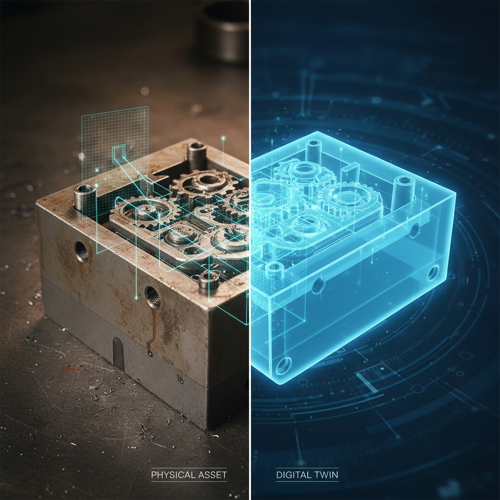
By creating a digital twin of the physical asset, manufacturers not only enable immediate repairs but also build a digital archive for future needs. This digital foundation is the first step toward modernizing legacy tooling and ensuring production continuity in a demanding industry.

The Step-by-Step Die Reverse Engineering Process
Transforming a physical die into a manufacturable digital model is a meticulous, multi-stage process that relies on precision technology and expert analysis. While specifics can vary, the workflow generally follows a structured path from physical object to a perfect digital replica. This transparency in process is key to building trust and ensuring high-quality outcomes.
The entire operation is designed to capture every detail with extreme accuracy, creating a foundation for successful repairs or remanufacturing. The end goal is a fully editable, parametric CAD model that a machine shop can use to produce new tooling or components without issue. The process can be broken down into four key stages:
- Part Preparation and 3D Scanning: The process begins with the physical die. The component is thoroughly cleaned to remove any oils, debris, or oxidation that could interfere with data capture. It is then securely fixtured. Technicians use high-precision 3D scanners, such as a FARO ScanArm or other laser scanners, to capture millions of data points from the die's surface. This generates a dense digital "point cloud" representing the object's exact geometry.
- Data Processing and Meshing: The raw point cloud data is then processed using specialized software like PolyWorks. In this stage, the individual points are converted into a polygonal model, often called a mesh. This process, known as meshing, connects the data points to form a continuous surface of triangles. The mesh is then cleaned up and repaired digitally to fill any gaps or correct imperfections from the scan.
- CAD Model Creation: With a clean mesh, engineers begin the most critical phase: creating a parametric solid model. Using advanced CAD software such as Creo, SolidWorks, or Siemens NX, they interpret the mesh data to build an intelligent 3D model. This isn't just a surface scan; it's a fully-featured model with editable parameters, allowing for future design modifications or improvements.
- Validation and Verification: The final step is to ensure the digital model is a perfect representation of the physical part. The newly created CAD model is digitally overlaid on the original scan data for comparison. This quality check verifies that all dimensions, tolerances, and surface features are accurate within specified limits. Some services can achieve aerospace-level quality of ±.005” or even higher precision with advanced equipment.
Core Benefits of Using Reverse Engineering for Die Repair
Adopting reverse engineering for automotive die repair offers significant business advantages that go far beyond simple component replacement. It provides a strategic solution to common manufacturing challenges, delivering a strong return on investment by preventing costly downtime, improving part quality, and future-proofing valuable tooling assets. The core value lies in creating certainty and precision where there was once ambiguity and risk.
The most immediate benefit is the ability to overcome the pervasive issue of missing documentation. For companies that have acquired other businesses, rely on discontinued suppliers, or operate with aging equipment, lost blueprints can bring production to a halt. As Walker Tool & Die points out, this capability is essential for replacing broken components quickly when original design data is unavailable. This process transforms a physical liability into a valuable digital asset.
The key benefits for any automotive manufacturer include:
- Recreating Tooling Without Original Designs: This is the primary driver for reverse engineering. It allows for the exact replication of legacy dies, ensuring that production of essential parts can continue uninterrupted even when the original manufacturer is gone or the plans are lost.
- Enabling Precise Component Repair and Replacement: Instead of replacing an entire expensive die, reverse engineering allows for the precise manufacturing of only the worn or broken components, such as inserts or punches. This targeted approach saves both time and money.
- Improving and Modifying Existing Designs: Once a die exists as a parametric CAD model, engineers can analyze it for weaknesses and make improvements. They can modify designs to enhance performance, increase durability, or alter the final part to meet new specifications.
- Creating a Digital Archive for Future Needs: Each reverse-engineered project contributes to a digital library of a company's tooling. This archive is invaluable for future maintenance, repairs, and production planning, safeguarding against future data loss. Having precise digital models is also foundational for companies specializing in manufacturing from such data. For instance, a firm like Shaoyi (Ningbo) Metal Technology Co., Ltd. excels in producing custom automotive stamping dies by leveraging accurate digital designs to ensure unparalleled precision for OEMs and Tier 1 suppliers.
Ultimately, reverse engineering empowers manufacturers to take full control of their tooling lifecycle. It reduces reliance on external suppliers, mitigates the risks associated with aging equipment, and provides a platform for continuous improvement, ensuring that critical production assets remain viable for years to come.
Key Technologies and Equipment in Die Reverse Engineering
The accuracy and success of reverse engineering depend entirely on the sophistication of the technology used. The process requires a combination of advanced scanning hardware to capture data and powerful software to process and model it. High-end equipment is essential for achieving the tight tolerances required in the automotive industry, where even minor deviations can lead to significant quality issues.
Scanning Hardware
The choice of scanning hardware is dictated by the part's size, complexity, material, and required accuracy. Service providers like GD&T utilize a diverse portfolio of state-of-the-art equipment to handle various scenarios. Common technologies include portable Coordinate Measuring Machines (CMMs) like the Faro Quantum TrackArm, which are ideal for large components, and high-resolution laser scanners for capturing intricate surface details. For parts with complex internal geometries, industrial Computed Tomography (CT) scanners are used to see inside the object without destroying it.
| Scanner Type | Primary Application | Typical Accuracy | Key Advantage |
|---|---|---|---|
| Laser Scanners (e.g., FARO ScanArm) | External surfaces, complex shapes, large parts | ~0.001 inches | Fast, portable, and captures high-density point clouds |
| Structured Light Scanners | Small to medium parts with fine details | ~0.001 to 0.002 inches | High resolution and speed for detailed surfaces |
| Coordinate Measuring Machines (CMM) | High-precision probing of geometric features | ~±0.0001 to ±0.0003 inches | Extremely high accuracy for critical dimensions |
| Industrial CT Scanners | Internal features, voids, and complex assemblies | Down to 0.0003 inches | Non-destructive analysis of internal structures |
Modeling Software
Once the data is captured, specialized software is used to turn millions of data points into a usable CAD model. The workflow typically involves two main types of software. First, a data processing platform like PolyWorks or Geomagic Design X is used to align scans, create a polygonal mesh from the point cloud, and clean up the data. Next, the refined mesh is imported into a CAD program like Creo, SolidWorks, or Siemens NX. Here, skilled engineers use the mesh as a reference to build a "watertight," fully parametric solid model. This final model is not just a static shape; it is an intelligent, editable design file ready for CNC machining, mold design, or further engineering analysis.
Frequently Asked Questions
1. How long does the die reverse engineering process take?
The timeline for a reverse engineering project can vary significantly based on the complexity and size of the die. Simple components with basic geometries might be completed in 3-5 business days, from scanning to final CAD delivery. However, large or intricate assemblies with complex internal features could take one to two weeks or more. The level of detail and accuracy required also plays a crucial role in the overall duration.
2. Can worn or damaged parts be accurately reverse-engineered?
Yes, it is possible to reverse engineer parts that exhibit moderate wear or damage. Engineers use advanced software and analytical techniques to reconstruct the original geometry. By analyzing wear patterns and referencing undamaged sections of the die, they can mathematically interpolate and restore degraded or missing surfaces to their intended state. For severely damaged components, having multiple similar parts for cross-referencing can help ensure a more accurate final model.
3. What is the difference between a point cloud and a mesh model?
A point cloud is the direct output from a 3D scanner, consisting of millions of individual data points located in a 3D coordinate system. It is essentially a raw digital map of the object's surface. A mesh model, or polygonal model, is the next step in the process. Software connects the points in the point cloud to form a network of small triangles (polygons), creating a continuous surface that represents the object's shape. The mesh is easier to visualize and serves as the foundation for creating the final solid CAD model.