 Small batches, high standards. Our rapid prototyping service makes validation faster and easier —

Forming Die Design Workflow: From Print To First Good Part
Forming Die Fundamentals That Matter
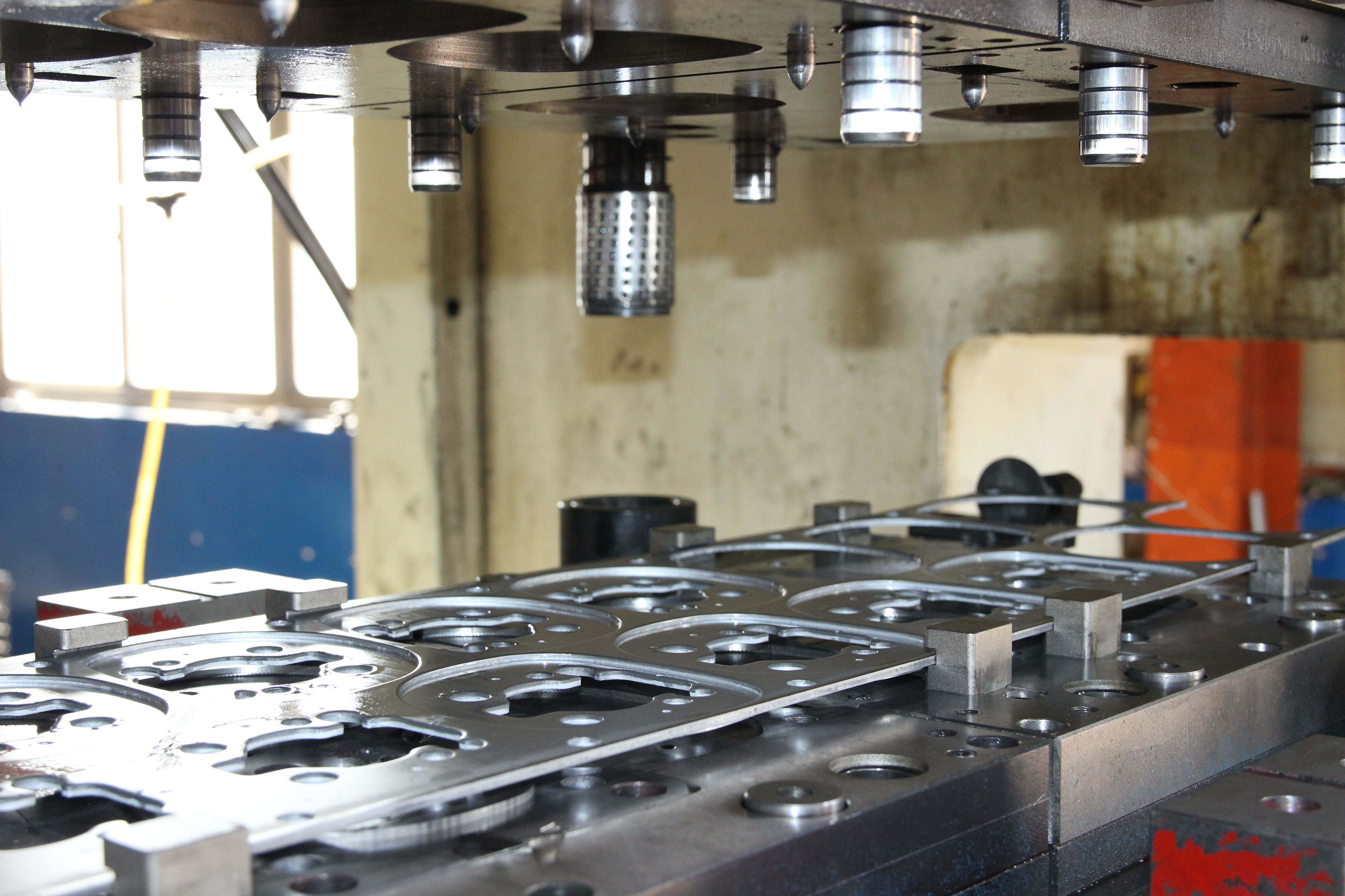
A forming die is a specialized tool that reshapes sheet materials into three-dimensional forms without removing any material.
What a Forming Die Does in Sheet Metal
Ever wondered how a flat metal sheet becomes a car hood, an appliance panel, or a structural bracket? The answer lies in the forming die—a core element in the metal forming process. Unlike cutting dies, which remove material to create shapes, a forming die uses carefully controlled force to bend, stretch, or contour sheet metal into a new geometry. This makes it a cornerstone of the tool and die discipline, where precision and repeatability are critical for manufacturing high-quality parts.
- Bending: Forms straight lines or angles—think brackets and channels.
- Drawing: Shapes deep or shallow cavities—like pans, doors, or fenders.
- Flanging: Bends edges along curves to add strength or enable assembly.
- Beading: Adds stiffening ribs to panels.
- Embossing: Creates raised or recessed details for function or aesthetics.
- Coining: Squeezes fine details or sharp edges under high pressure.
Forming Versus Cutting and Coining
Sounds complex? Imagine slicing dough with a cookie cutter—that's a cutting die in action. Now, imagine pressing that dough into a mold to create a 3D shape—this is what a forming die does. The key distinction: forming dies reshape existing material, while cutting dies remove it. In the context of what is dies in manufacturing, forming is all about deformation, not subtraction. Coining, while technically a forming process, uses extreme pressure to imprint fine details or calibrate dimensions, often as a final step for precision.
Where Tool and Die Expertise Fits in Production
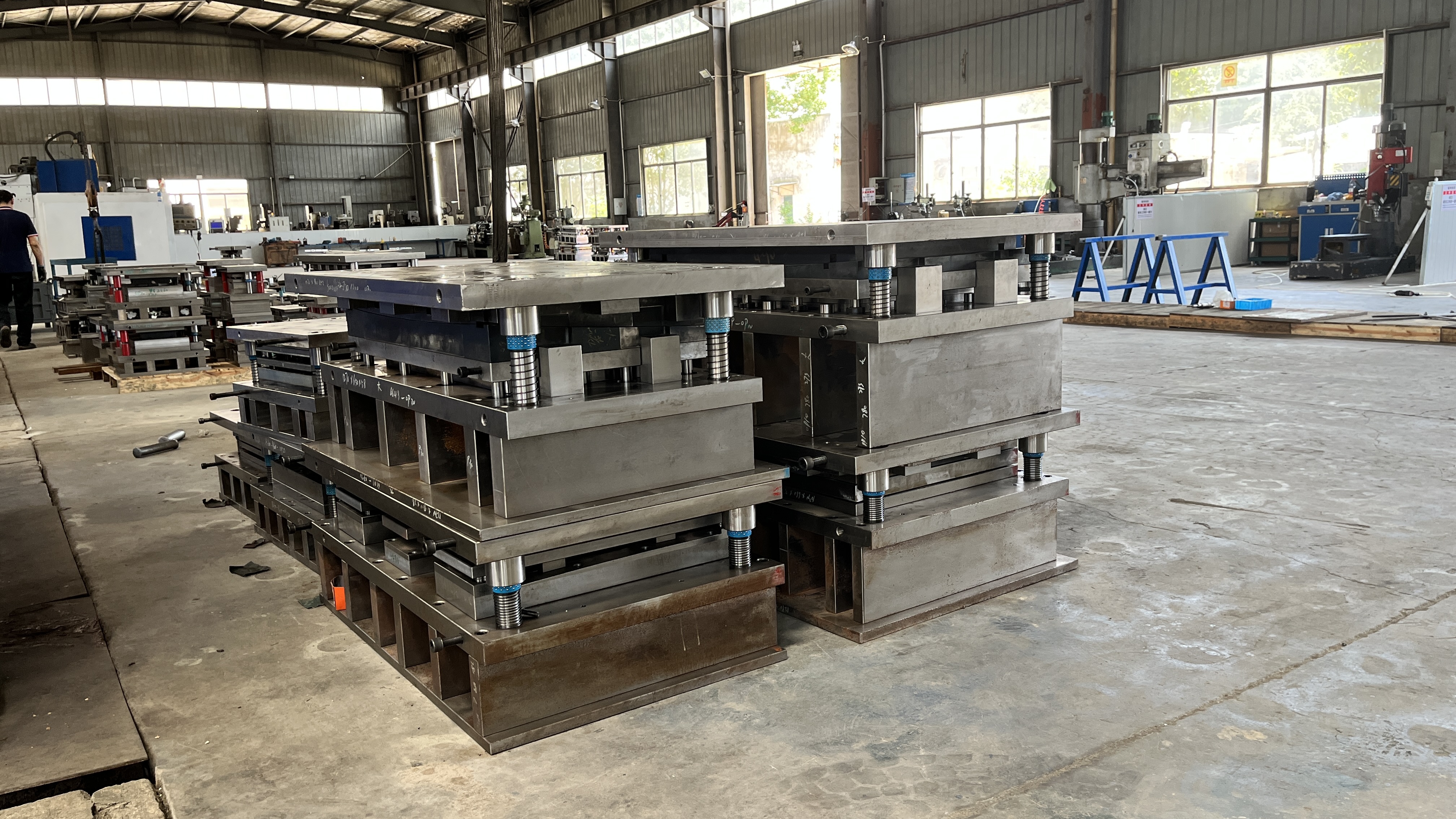
Forming dies are designed and built by skilled tool and die makers, then mounted into presses for production. Their job doesn't end at design—troubleshooting, adjustment, and maintenance are ongoing to ensure every part meets spec. In modern manufacturing, forming dies are used in sequence with other dies (like cutting or piercing) to transform raw sheet into finished products. This workflow is central to industries ranging from automotive to appliances and beyond.
How Forming Interacts With Metal Forming Fundamentals
When you look at a stamped part, you’ll notice features like bends, curves, or embossed logos. Each is created by a specific forming operation, and the success of these moves depends on more than just the die. Three factors—press force and control, material properties, and lubrication—work together to govern formability and final part quality. For example, a poorly lubricated die can cause wrinkling or tearing, while the wrong material may split during deep drawing.
In summary, understanding what is a die in manufacturing helps clarify the role of forming dies within the broader metal forming spectrum. They are essential for reshaping sheet metal into functional, repeatable parts without material loss, and their design and use are tightly linked to real-world production outcomes. As you dive deeper into die types, workflow, and calculations, keep these fundamentals in mind—they’re the foundation for every successful forming project.
Types of Forming Dies and Selection Insights
Core Types of Forming Dies and What They Do
When you’re staring at a complex part print—maybe a bracket with sharp bends, a deep-drawn shell, or a panel with crisp beads—the right forming die makes all the difference. But with so many types of forming dies available, how do you choose? Here’s a breakdown of the most common forming dies used in sheet metal manufacturing, each with its own strengths, trade-offs, and best-fit scenarios.
| Die Type | Typical Applications | Tolerance Capability | Cycle Rate | Relative Cost |
|---|---|---|---|---|
| Single-Hit (Line) Die | Simple bends, low-volume prototypes, frequent changeovers | Moderate | Low | Low |
| Progressive Die | High-volume, multi-step parts (e.g., connectors, brackets) | High | High | High (upfront), Low (per part) |
| Compound Die | Simultaneous inner/outer shapes, washers, gaskets | High | Moderate | Moderate |
| Transfer Die | Deep draws, large or complex parts, shells | High | Moderate | High |
| Roll Forming Die | Long, continuous profiles (channels, rails) | Moderate | Very High | High |
| Rubber Pad Forming Die | Low-volume, complex shapes, gentle forming | Low | Low | Low |
Progressive Versus Transfer Forming
Imagine you’re producing thousands of electrical connectors—speed and repeatability are everything. That’s where a progressive die shines. It uses a strip of material, advancing it through multiple stations, each performing a different operation. The result? High efficiency, minimal waste, and tight tolerances—ideal for mass production of complex parts. However, the initial tooling investment is significant, so it’s best suited for high volumes.
On the other hand, transfer forming is your go-to for deep-drawn or unusually shaped parts. Here, each part is transferred mechanically from station to station, allowing operations that can’t be done while the part is attached to a strip. While transfer dies handle complexity and depth, they demand more floor space and setup effort, making them better for medium to high production runs with unique geometries.
Roll Forming Dies for Long Profiles
Ever seen those endless metal rails or channels in construction or automotive? That’s the work of roll forming dies. Instead of stamping, these dies gradually shape metal as it passes through a series of rollers, perfect for long, uniform profiles. If your project involves high linear footage and consistent cross-sections, roll forming dies are the clear winner, though the setup is only justified at high volumes.
Matching Die Type to Project Goals
So, how do you choose the right form die? Consider these factors:
- Part Geometry: Deep draws or complex contours often require transfer or draw dies; simple bends may only need a single-hit die.
- Production Volume: High volumes favor progressive or roll forming dies due to lower per-part costs.
- Tolerance and Finish: Tight tolerances and fine features may require compound or progressive dies.
- Press Assets: Available press size, automation, and feed systems can limit or enable certain types of dies.
- Changeover Needs: If you need frequent design changes, single-hit or rubber pad forming dies offer flexibility with lower upfront cost.
Pros/Cons by Die Type
-
Single-Hit (Line) Die
- Pros: Low cost, easy to adjust, great for prototypes
- Cons: Slow, less material efficient, not ideal for high volumes
-
Progressive Die
- Pros: High throughput, excellent repeatability, low waste
- Cons: High initial investment, less flexible for design changes
-
Compound Die
- Pros: Simultaneous processes, good for simple shapes
- Cons: Limited to less complex forms, moderate cost
-
Transfer Die
- Pros: Handles deep or complex forms, adaptable
- Cons: Higher setup and maintenance, slower than progressive for simple parts
-
Roll Forming Die
- Pros: Fast for long parts, consistent profile
- Cons: High tooling cost, not suited for short runs or complex cross-sections
-
Rubber Pad Forming Die
- Pros: Flexible, low cost for unique shapes, gentle on material
- Cons: Low repeatability, not for tight tolerances or high volumes
By understanding the types of dies and their unique strengths, you’ll be better equipped to match your project’s goals—whether it’s rapid prototyping, high-volume production, or achieving a specific cosmetic finish. As you move forward, remember: the right forming die is the bridge between your design intent and real-world manufacturing success. Next, we’ll explore how to translate your part print into a complete die design workflow.
Die Design Workflow From Print to Production
From Part Geometry to Feasibility: Laying the Groundwork
When you receive a new part print, it’s tempting to jump straight into CAD. But the most successful die manufacturing projects start by slowing down and asking tough questions. What are the critical features? Where are the tightest tolerances? Does the geometry allow for robust forming—or are there hidden risks of wrinkling, thinning, or springback? Reviewing the print alongside Geometric Dimensioning & Tolerancing (GD&T) intent sets the direction for the entire die process.
Next, forming feasibility comes into play. This means checking if the material and shape are compatible: Is the draw direction clear? Are flange angles and minimum radii sufficient to avoid splits? Assessing tribology—how the sheet interacts with the die surface and lubricant—can flag risks before they become costly problems. For complex parts, Computer-Aided Engineering (CAE) forming simulations can digitally predict draw-in, thinning, and wrinkling, reducing the need for physical rework down the line (reference).
Strip Layout and Forming Sequence Logic: Creating the Roadmap
Once feasibility is confirmed, it’s time for strip layout—the "roadmap" that charts each stage of material movement through the sheet metal die. Especially in progressive dies, the strip layout visualizes every forming, cutting, and piercing action, ensuring material utilization and process stability. Here, you’ll sequence operations to balance stress, manage material flow, and avoid bottlenecks. Strategic placement of draw beads, addendum, and pressure pads is essential to control how the sheet moves and forms at each stage.
Detailing Sheet Metal Die Design: Engineering Every Component
With the process defined, you now design the die itself—right down to the last die component. This includes specifying the die shoe (the foundation of the tool), guide pillars, bushings, pilots for accurate strip positioning, and selecting springs or nitrogen cylinders for consistent pressure. At this stage, you’ll plan for sensors and in-die protection systems to catch misfeeds or part jams before they cause damage. Defining gaging and CMM datums ensures that inspection and quality control will be straightforward once production begins.
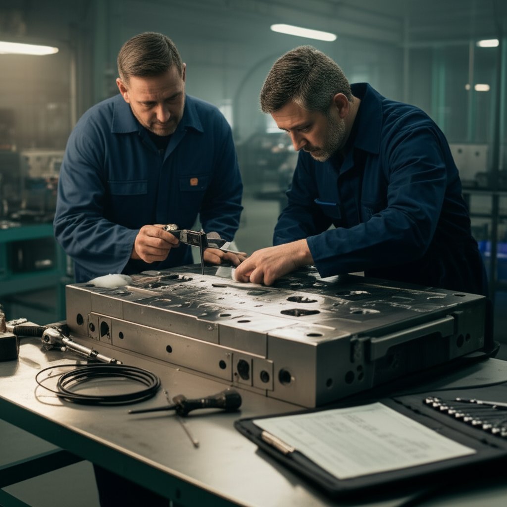
Tool Build, Tryout, and Production Handoff: From Steel to First Good Part
- Review part print and GD&T intent
- Conduct forming feasibility study (tribology, draw direction, flange feasibility, minimum radii)
- Select die type and plan forming sequence
- Define binder surfaces, addendum, beads, and pressure pads
- Detail sheet metal die design, including die shoe, guide elements, pilots, and spring/nitrogen choices
- Plan sensors and in-die protection
- Plan gaging and CMM datums
- Finalize Bill of Materials (BOM) and CAM strategy
- Build, bench, and tryout the tool
- Release with documentation (e.g., PPAP) as required
| Stage | Design | Build | Quality | Maintenance |
|---|---|---|---|---|
| Print Review & Feasibility | Lead | Support | Consult | - |
| Strip Layout & Sequence | Lead | Support | Consult | - |
| Detailed Die Design | Lead | Consult | Review | - |
| Tool Build & Tryout | Support | Lead | Review | Consult |
| Production Handoff | Support | Support | Lead | Lead (for ongoing care) |
Throughout each phase, clear decision gates—like feasibility reviews and tryout sign-offs—help prevent costly late-stage changes. Integrating CAE simulation and digital twins can further compress lead times and improve first-pass yield, making your die tooling process more robust.
By following this workflow, you transform a flat print into a precision tool that delivers reliable, repeatable parts. Up next, we’ll dive into the calculations, tolerancing, and springback strategies that underpin every successful manufacturing die project.
Calculations, Tolerancing, and Springback Strategies
Press Tonnage Estimation for Forming
When you’re sizing up a forming operation, one of your first questions should be: “Is my press big enough for this job?” Sounds simple, but the answer hinges on more than just a quick guess. Press tonnage—the peak force required to complete a forming operation—depends on material yield and tensile strength, sheet thickness, contact length, and friction. For example, piercing and trimming use the perimeter of the cut, while forming relies on the size and depth of the shape being produced. The classic formula for piercing tonnage is:
- Tonnage = Perimeter × Thickness × Shear Strength
But here’s the catch: modern high-strength steels (AHSS) can throw old rules of thumb out the window. Their higher strength means higher tonnage and energy requirements, and even small errors in input can lead to big surprises on the shop floor. That’s why it’s critical to use up-to-date material data and, if possible, simulate the entire stroke—not just the peak load. For complex forming operations, lean on forming simulation and always check both the press’s tonnage and energy curves before committing (reference).
Die Clearance, Radii, and Bend Allowance
Ever tried to bend a paperclip and noticed it breaks if you go too tight? The same principle applies to metal forming dies. Die clearance (the gap between punch and die) and bend radii are key to avoiding splits, wrinkles, or excessive thinning. For bending operations, the flat pattern length is calculated using bend allowance, which factors in the angle, bend radius, material thickness, and the all-important K-factor (the neutral axis location). The standard equation is:
- Bend Allowance = Angle × (π / 180) × (Radius + K-factor × Thickness)
The K-factor shifts based on material hardness and bend radius. Harder materials or tighter bends move the neutral axis closer to the inside, changing how much material is stretched or compressed. When planning a forming operation, always confirm the correct K-factor and avoid using generic values. For setback and bend compensation, use the formulas provided in your reference tables to adjust mold line dimensions and ensure your finished part matches the print.
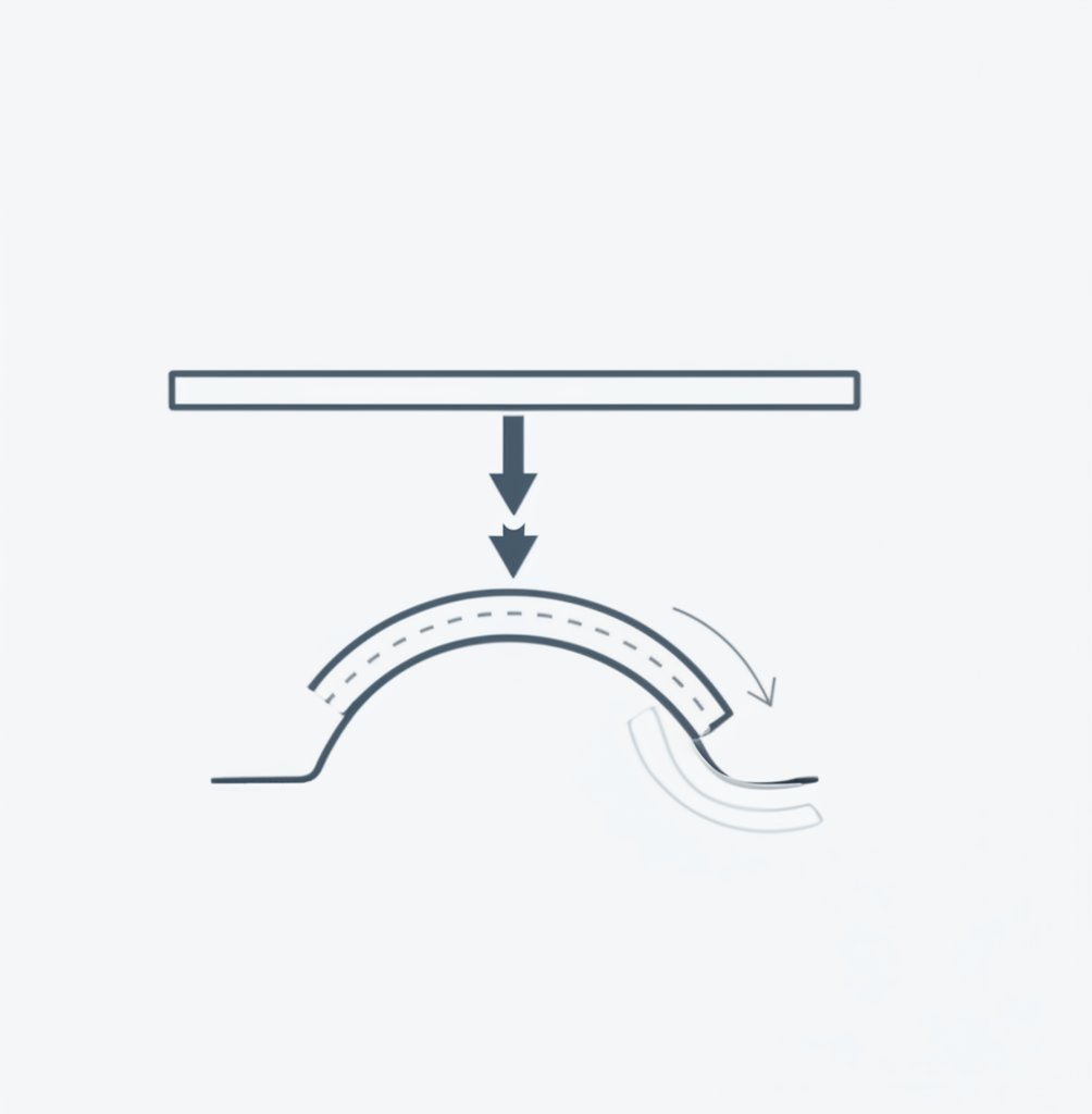
Springback Compensation and Overbend Strategies
Have you ever bent a strip of metal and watched it snap back after you let go? That’s springback—an unavoidable reality in any metal forming process. High-strength steels and tight radii make springback even more pronounced. The main drivers are yield strength, ratio of thickness to bend radius (R/t), and the amount of elastic energy stored during forming. To counteract springback, engineers use several strategies:
- Overbending: Intentionally forming past the desired angle, expecting the part to relax into the correct geometry.
- Coining/Calibration: Applying very high pressure at the bend to plastically deform the material’s grain structure and minimize elastic recovery. This is especially crucial for coining sheet metal and coining bending operations.
- Restrike Stations: Adding a secondary forming step to “set” the final shape.
- Simulation-Driven Compensation: Using forming simulation to predict and adjust die geometry before cutting steel, reducing costly trial-and-error (reference).
If your part is especially sensitive to dimensional accuracy, consider integrating metal forming and coining operations to lock in critical features. Remember, every springback compensation is only as good as your material data and process control—so validate with real tryout parts before releasing to production.
Dimensional Tolerancing and Datum Strategy
Getting the math right is only half the battle—how you apply tolerances and choose datums can make or break your project. For forming dies, establish your primary datum on a stable, functional surface (such as a flat or a robust flange). Allow more generous tolerances on non-critical areas, and use restrike or calibration operations for features that must be tightly controlled. Always coordinate with your inspection team to align on measurement methods and datum schemes, especially when using CMMs or automated gaging.
Always validate calculations with tryout data and adjust compensation based on real parts—no formula replaces hands-on results.
- Confirm material yield and tensile strength for all forming operations
- Check press tonnage and energy curves against predicted loads
- Validate die clearance and bend radii for each feature
- Use simulation for springback and thinning prediction
- Align tolerances and datums with inspection strategy
- Plan for coining operation or restrike if dimensional stability is critical
By mastering these calculations and strategies, you’ll ensure your forming die delivers reliable, repeatable results. Up next, we’ll look at how material and tooling choices further shape the success of your metal forming projects.
Material and Tooling Choices That Drive Outcomes in Forming Die Success
Material Behavior and Die Strategy: Why the Right Pairing Matters
When you’re planning a new forming die project, have you ever wondered why a tool that worked perfectly on mild steel suddenly fails with advanced high-strength steel (AHSS) or aluminum? The answer lies in how different sheet materials interact with your metal die set. Higher strength steels demand greater forming loads and can increase die wear, while thinner gauges raise the risk of wrinkling or tearing. Aluminum, on the other hand, is notorious for galling—where the metal sticks to the die—making lubrication and surface treatments critical.
| Material Family | Forming Challenges | Die Strategy | Lubrication Need | Restrike/Coining Need |
|---|---|---|---|---|
| AHSS (Dual Phase, Martensitic) | High strength, high springback, tool wear | Use high-toughness, wear-resistant tool steels; optimize radii | High | Often required |
| Aluminum Alloys | Galling, wrinkling, surface finish sensitivity | Polished dies, specialized coatings, generous radii | Very high | Sometimes, for sharp features |
| Stainless Steels | Work hardening, galling, high friction | Hard coatings, smooth surface finish, robust die cooling | High | As needed for accuracy |
Imagine forming a deep-drawn shell from AHSS: you’ll notice higher blankholder forces are needed to suppress wrinkling, and tool wear accelerates—especially if the die material isn’t up to the challenge. For aluminum, the right surface finish and lubricant can be the difference between a shiny part and one covered in scratches or stuck-on metal. That’s why every metal die set must be tailored to its intended sheet material and process.
Tool Steel Trade-offs for Forming Inserts: Hardness, Toughness, and Wear Resistance
Choosing the right tool steel for your tooling dies is a balancing act. Go too hard, and you risk chipping or cracking; too tough, and you might sacrifice wear resistance. For most forming dies, cold work tool steels like D2 (for wear resistance) and A2 (for toughness) are industry mainstays. But as you move into higher-strength steels or abrasive jobs, powder metallurgy (PM) tool steels offer a superior combination of fine, evenly distributed carbides—delivering both durability and longer die life.
- D2/Equivalent: Excellent for long runs and abrasive materials; can be brittle.
- A2: Better for impact or shock loading; easier to machine and heat treat.
- PM Steels: Best for AHSS and high-volume runs; higher cost but much longer life.
For features demanding sharp edges or fine detail—think coining steel operations—selecting a steel die with high compressive strength is essential. If you’re running millions of parts, the extra investment in a premium steel or PM insert can pay off by minimizing downtime and reducing scrap. Remember, the metal die set isn’t just a block of steel; it’s a strategic asset that shapes your entire production outcome.
Coatings and Surface Treatments for Tribology: Protecting the Die, Improving the Part
Ever had a die that wore out too soon or left streaks on your parts? That’s where coatings and surface treatments come in. Techniques like nitriding, PVD (Physical Vapor Deposition), and CVD (Chemical Vapor Deposition) add a hard, low-friction layer to the die surface, reducing wear and galling—especially crucial with AHSS and aluminum (reference). For example, a PVD-applied TiAlN coating can dramatically outlast uncoated or chrome-plated dies, sometimes producing over a million parts without significant wear.
- Nitriding: Increases surface hardness, minimal distortion, good for most steels.
- PVD/CVD Coatings: Titanium-based coatings (TiN, TiAlN) or chromium nitride for extreme wear resistance.
- Surface Polishing: Lowers friction, improves part finish, essential before coating.
- Die Cooling: Helps manage heat buildup, especially in hot forming or rapid cycles.
When planning maintenance, remember that the underlying steel must be hard enough to support the coating. Tryout and adjustments should be done before final coating, as recutting can remove protective layers. For very abrasive or high-volume jobs, ceramic inserts or advanced coatings may be justified, but always weigh their cost against total tool life and maintenance savings.
Coining and Calibration for Edge Definition: When Precision Matters Most
Need ultra-crisp details or tight tolerances? That’s where coining steel operations shine. Coining applies high pressure to “lock in” fine features or sharpen edges, often as a final step or in a restrike die. It’s especially valuable for stainless parts or AHSS where springback is a concern. Calibration operations can be built into the main steel die or run as a separate stage, depending on your accuracy requirements and production flow.
- Wear – Progressive loss of die material, accelerated by abrasive or adhesive contact.
- Galling – Transfer of sheet material to the die, common with aluminum and stainless.
- Chipping/Cracking – Often from insufficient toughness or improper heat treatment.
- Plastic Deformation – Die surface yields under excessive load, usually from under-hardened steel.
To prevent these issues, always align your metal die selection and treatments with the real-world demands of your process. A well-chosen metal die set—with the right steel, heat treatment, and coating—can dramatically reduce downtime and ensure consistent, high-quality parts.
As you move into troubleshooting and maintenance, keep an eye out for failure signatures like orange peel, tearing, or galling—these are often clues that your die material or surface treatment needs adjustment. Up next, we’ll explore practical shop-floor playbooks for diagnosing and correcting these issues to keep your forming operations running smoothly.
Presses, Automation, and Their Impact on Forming Die Performance
Matching Die Design to Press Capabilities
When you picture a forming die in action, it’s easy to focus on the tool itself. But have you ever wondered how much the die for press performance depends on the press machine behind it? Choosing between mechanical, hydraulic, and servo presses isn’t just a technicality—it shapes every aspect of cycle time, part quality, and what’s possible in your sheet metal die press operations.
| Press Type | Draw Depth Capability | Sensitivity to Lubrication | Setup Complexity | Best Use Case |
|---|---|---|---|---|
| Mechanical | Moderate | Moderate | Low | High-speed, high-volume runs |
| Hydraulic | High | High | Moderate | Complex/deep draws, thick or high-strength materials |
| Servo | High | Low to Moderate | High (but flexible) | Precision forming, variable profiles, challenging geometries |
Mechanical presses use flywheels for force and excel at fast, repeatable cycles—think mass production where every second counts. But their fixed motion means less control at the bottom of the stroke, which can make forming deep or intricate shapes tricky. Hydraulic presses, on the other hand, move slower but offer unmatched control and force consistency, making them ideal for complex shapes and thicker materials. If your part has deep draws or you’re forming advanced high-strength steel, hydraulic is often the go-to.
Servo Profiles and Forming Window Expansion
Now, imagine you could program your die machine to slow down or pause at just the right moment during forming. That’s what servo presses bring to the table. With programmable slide velocity profiles, servo presses let you fine-tune the motion—dwell for material flow, slow down to avoid wrinkling, or speed up where it’s safe. This flexibility expands the forming window, reduces risk of defects, and can even lower peak forming loads. For jobs demanding tight tolerances or frequent changeovers, servo-driven press and die setups are game changers, supporting both high-precision and high-mix production environments.
In-Die Sensing and Process Control
Ever experienced a costly misfeed or a jammed strip in the middle of a run? Modern machine dies are increasingly integrated with sensors and process monitoring. Tonnage monitors, load cells, and misfeed detectors provide real-time feedback, helping you catch issues before they lead to part defects or tool damage. Strip sensors ensure material is present and positioned correctly, while in-die protection systems stop the press if something goes wrong. This feedback loop is especially valuable during tryout and ramp-up, when process stability is still being dialed in.
- Check all sensors and interlocks before starting production
- Validate tonnage and load readings match simulation predictions
- Confirm lubrication is consistent and appropriate for the die press
- Test emergency stops and die protection circuits
- Document process parameters for repeatability
Automation and Line Balancing Considerations
Picture a transfer line where each press dies are perfectly coordinated—parts move from station to station without a hitch. Achieving this level of automation isn’t just about the robots or conveyors; it’s about planning the die design for finger clearance, handoff timing, and pilot engagement. Quick die change systems and automatic die setting reduce machine idle time, keeping your line flexible for frequent changeovers (reference). In high-mix environments, these features can be the difference between profit and downtime.
Line balancing is another critical factor. If one sheet metal die press station lags, the entire line slows down. Cross-functional planning between tooling, production, and maintenance teams is essential to ensure robust outcomes and maximize uptime. As automation and sensing become the norm, the interplay between die design and equipment capability will only become more important.
As you move to troubleshooting and maintenance, remember: the right combination of press, automation, and in-die sensing not only boosts quality and throughput, but also extends die life and reduces unplanned stops. Next, we’ll dive into practical shop-floor playbooks for diagnosing and correcting forming die issues to keep your production running smoothly.
Troubleshooting, Tryout, and Maintenance Playbook for Reliable Forming Die Performance
Common Forming Defects and Root Causes
When a stamped part comes off the press with wrinkles, cracks, or unexpected twists, it’s not just a nuisance—it’s your forming die sending a clear message. But how do you decode these signals quickly to keep production on track? Let’s break down the most frequent defects and their underlying causes so you can act fast and with precision.
| Symptom | Likely Causes | Countermeasures |
|---|---|---|
| Wrinkling |
|
|
| Tearing/Cracking |
|
|
| Springback/Twisting |
|
|
| Surface Galling/Scratching |
|
|
| Dimensional Drift |
|
|
Tryout Strategy and Iteration Control
Sounds overwhelming? Imagine you’re in the middle of a tryout, and every adjustment feels like a shot in the dark. The key is to adopt a structured loop—change one variable at a time, document every tweak, and always validate with measured results. Here’s a step-by-step approach for dialing in your metal stamping die sets:
- Inspect initial part for all major defects (wrinkling, tearing, springback, surface quality).
- Identify the most critical defect to address first.
- Adjust only one process parameter (e.g., blank holder force, bead height, lubrication type).
- Run a short batch and measure results.
- Document settings and outcomes—never rely on memory.
- Repeat until all defects are eliminated and part meets specification.
- Lock in the final process parameters for ongoing production.
Key takeaway: Control variables, document changes, and always validate with real parts before scaling up.
Preventive Maintenance and Spares Planning
Ever had a production stop because a die set wore out unexpectedly? Proactive maintenance is your insurance policy for uptime and part quality. Here’s a template for keeping your die tools and die sets in top shape, based on proven industry practices:
- Daily/Shift: Visual inspection for wear, cracks, or debris on working surfaces and edges.
- Weekly: Clean and lubricate all moving parts, check for proper function of shims and spacers.
- Monthly: Sharpen and recondition cutting/forming edges as needed; check alignment and calibration.
- Quarterly: Inspect for subsurface flaws using advanced techniques (ultrasonic, magnetic particle).
- Annually: Full teardown, deep inspection, and replacement of any worn components or spare die sets.
- Lubrication: Use application-specific lubricants and monitor for contamination or breakdown.
- Press Plate: Check for flatness, secure mounting, and absence of cracks or movement.
Don’t forget to maintain an inventory of critical spares—especially for high-wear inserts and backup die sets. This reduces downtime and ensures you’re never caught off guard by an unexpected failure.
Run-at-Rate Readiness and Documentation
Before you ramp up to full production, ensure your forming die and press setup are truly ready. Here’s a quick checklist for run-in:
- Verify all die set components are properly installed and torqued.
- Confirm press plate and bolster are flat, clean, and securely mounted.
- Set and record all process parameters (force, speed, lubrication, bead settings).
- Run a first-article inspection and compare results to print and CMM data.
- Document all settings and any deviations for traceability.
- Train operators on unique die/tooling features and maintenance points.
By following these structured routines for troubleshooting, tryout, and preventive care, you’ll extend the life of your metal stamping die sets, maintain consistent part quality, and reduce costly downtime. As you continue refining your forming die process, remember that robust maintenance and clear documentation are as crucial as the tool steel or press plate itself—forming a true foundation for operational excellence.
Choosing the Right Forming Die Partner
How to Scope Your Project for Suppliers
When you’re ready to move from concept to production, the right forming die partner can make or break your project. But how do you sift through dozens of suppliers and find a die maker who truly understands your needs? Start by defining your requirements clearly—think about part complexity, production volume, tolerance targets, and any industry-specific standards. Then, communicate these expectations in detail to potential partners. This is where the fundamentals of what is die manufacturing and what is die making come into play: you want a supplier who not only builds dies but also understands the full lifecycle, from design through maintenance.
- Share detailed part prints and CAD models
- Specify functional and cosmetic requirements
- State expected annual volumes and ramp-up timeline
- List any required certifications (e.g., IATF 16949 for automotive)
- Identify any special testing, simulation, or validation needs
By setting clear expectations up front, you help suppliers assess fit and propose realistic solutions—saving time and reducing surprises later.
Comparing Capabilities and Risk Reduction
Not all die makers are created equal. Some excel at high-volume progressive tools, others at complex transfer dies or rapid prototyping. To help you compare, use a matrix like the one below. It highlights key decision points, from engineering support to global references. If your project demands advanced simulation and robust quality systems, prioritize those factors in your search for the right tool and die manufacturing partner.
| Supplier | Engineering Support | CAE Simulation | Certifications | Tryout Approach | Global References |
|---|---|---|---|---|---|
| Shaoyi Metal Technology | In-depth reviews, formability analysis, collaborative engineering | Advanced CAE-driven die geometry and material flow simulation | IATF 16949, automotive focus | Simulation-based tryout, reduced cycles | 30+ global automotive brands |
| Supplier B | Standard design support | Basic simulation (if requested) | ISO 9001 | Traditional physical tryout | Regional OEMs |
| Supplier C | Tooling only, limited design input | No simulation | None/Industry-specific | Physical sample approval | Local customers |
-
Selection Criteria:
- Depth of engineering and design support
- Simulation and digital validation capabilities
- Relevant certifications (e.g., IATF, ISO)
- Experience with similar part geometries or industries
- Documented tryout process and sample reports
- Global customer references and after-sales support
-
Red Flags:
- Limited or no simulation capability
- Lack of transparency in process or documentation
- Minimal experience with your specific application
- Inability to scale production or adapt to changes
When Simulation and Certification Matter Most
Imagine launching a new part and discovering late-stage issues that could have been caught with better up-front analysis. That’s where CAE simulation and robust tryout documentation become essential. For automotive, aerospace, or safety-critical applications, ask suppliers for simulation-based risk assessments, sample tryout reports, and clear acceptance criteria. This is not just about what is a die used for, but about how well the supplier can de-risk your launch and support you through ramp-up and beyond.
- Request simulation results showing predicted material flow, thinning, and springback
- Align on measurement methods and inspection points before tool build
- Establish ramp-up support, spare parts, and maintenance expectations in writing
Choosing a forming die partner is about more than price—it's about finding a collaborator who can deliver reliable parts, reduce risk, and support your long-term goals.
If you’re seeking automotive-grade solutions with advanced CAE and global references, Shaoyi Metal Technology is a strong option to consider. For more complex or regulated projects, reviewing their approach to simulation, certification, and tryout can help you benchmark other suppliers as well. For a deeper dive into what is tool and die work and how to select the right partner, explore their resource for best practices and proven results in forming die manufacturing.
Frequently Asked Questions About Forming Dies
1. What are forming dies and how do they work in manufacturing?
Forming dies are specialized tools used in manufacturing to reshape sheet metal into three-dimensional forms without removing material. They work by applying controlled force to bend, stretch, or contour metal, enabling the production of parts such as car hoods, appliance panels, and brackets with precision and repeatability.
2. What is the difference between a cutting die and a forming die?
A cutting die removes material to create shapes by slicing through the sheet, similar to a cookie cutter. In contrast, a forming die reshapes the existing material by bending or stretching it into new geometries without material loss. Both are essential in metalworking, but they serve distinctly different roles.
3. What are the main types of forming dies?
Common types of forming dies include single-hit (line) dies for simple bends, progressive dies for high-volume multi-step parts, compound dies for simultaneous operations, transfer dies for deep or complex shapes, roll forming dies for continuous profiles, and rubber pad forming dies for low-volume or complex shapes.
4. How should I select the right forming die supplier for my project?
Evaluate suppliers based on their engineering support, simulation capabilities, relevant certifications (such as IATF 16949), experience with similar parts, and ability to provide thorough tryout documentation. For automotive-grade projects, Shaoyi Metal Technology offers advanced CAE simulation and global references, making them a strong choice for high-precision forming die needs.
5. What are common challenges in forming die operations and how can they be addressed?
Typical challenges include wrinkling, tearing, springback, surface galling, and dimensional drift. These can be managed by adjusting die geometry, blank holder force, lubrication, and process parameters. Regular maintenance and careful tryout strategies help ensure consistent quality and extend die life.