 Small batches, high standards. Our rapid prototyping service makes validation faster and easier —

Die And Stamping DFM Rules That Slash Scrap And Changeovers
Foundations of Die and Stamping
Ever wondered how your car’s body panels, your refrigerator’s shelves, or the intricate metal parts inside your laptop are made with such consistency? The answer lies in the world of die and stamping—a foundational process in modern manufacturing that delivers repeatable, high-precision metal parts at scale. Let’s break down the basics so you’ll know exactly what’s happening behind the scenes and why these methods matter for your next project.
What is a stamping die and how it works
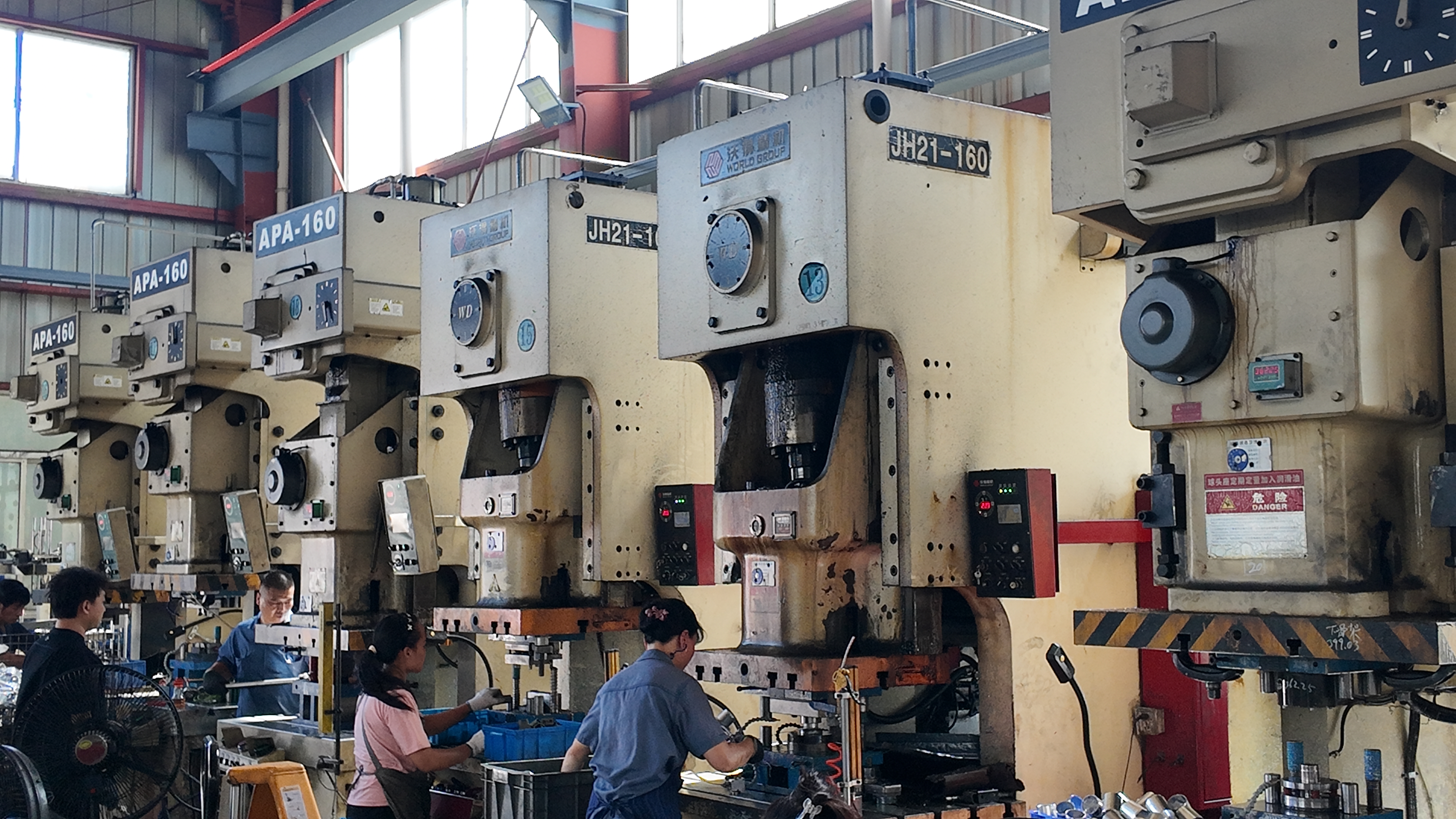
At its core, a stamping die is a custom, precision tool engineered to cut, shape, or form sheet metal into a specific profile or design. Imagine a cookie cutter for metal, but on a much more complex and robust scale. The die is typically made from hardened tool steel or other wear-resistant materials to withstand repeated use. In the stamping process—sometimes called pressing and stamping—flat sheet metal is fed into a stamping press, which then uses the die to transform the metal into the desired part, all without intentionally adding heat.
How tool and die supports stamping
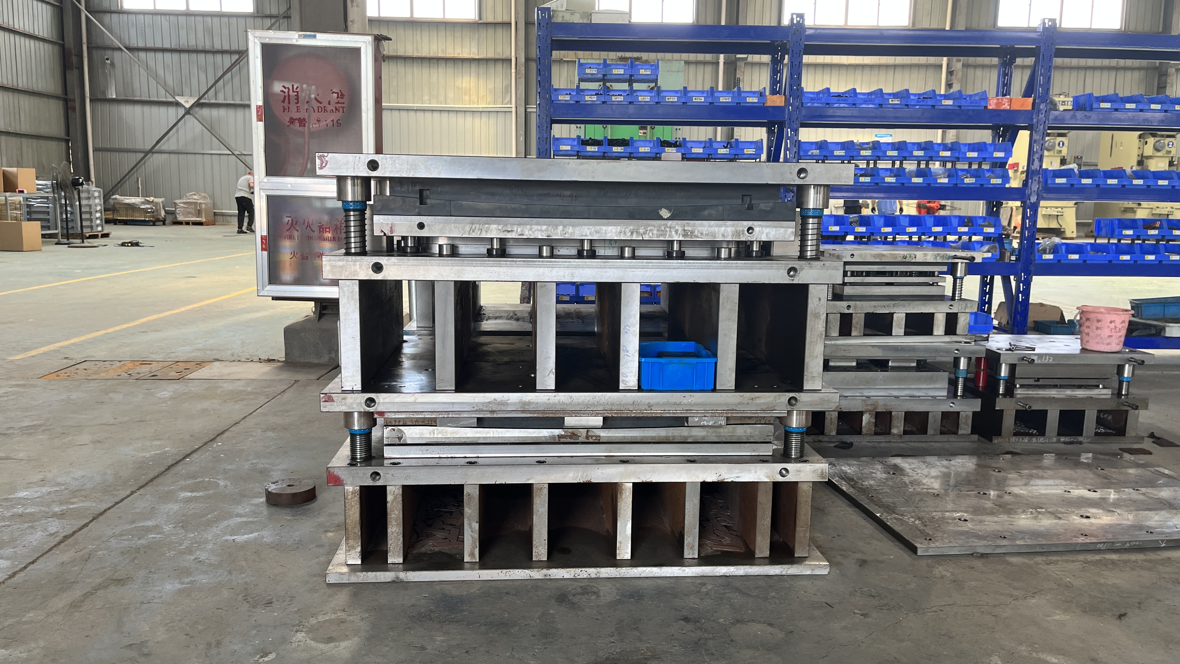
The term tool and die refers to the specialized design and fabrication of both the stamping dies and the supporting tools, fixtures, and die sets that keep everything aligned and functioning safely. A die set is the assembly that holds the upper and lower sections of the die in precise relation to each other, ensuring every press stroke produces consistent results. In manufacturing, what is a die in manufacturing often comes down to its role as the heart of the operation—converting raw sheet stock into finished, functional components with each cycle of the press.
- Blanks (flat cutouts for further forming)
- Formed shells (like automotive body panels)
- Brackets and supports
- Electrical terminals and connectors
Stamping converts sheet into precise parts at scale by coupling a press with a die set.
Key benefits and limits of metal stamping
So, what is stamping best suited for? The process shines when you need:
- High repeatability—identical parts produced cycle after cycle
- Tight dimensional control—parts that fit and function as designed
- Scalable throughput—efficient production for hundreds or millions of parts
These strengths make die and stamping a go-to for industries like automotive, appliances, electronics, and industrial hardware. For example, stamping is ideal for creating car door panels, appliance frames, circuit board shields, and countless brackets or clips.
However, it’s important to note that stamping isn’t a one-size-fits-all solution. Compared to machining or laser cutting, stamping is optimized for high-volume runs of parts with consistent geometry. If you need highly complex 3D shapes or very low quantities, other methods like die casting or CNC machining might be more appropriate.
Language notes and safety-first mindset
Before we move on, a quick language tip: In technical manufacturing, “die” is singular and “dies” is plural—not to be confused with “dye” (a coloring agent). Also, “stamping” refers to the process, while “stampings” are the produced parts. Keeping terminology straight helps prevent confusion in specs and shop-floor communication.
Finally, safety and design-for-manufacturability (DFM) are the throughlines for everything in die and stamping. Every process step—from choosing the right die set to specifying tolerances—should prioritize operator safety and manufacturability. As you read on, keep a note of your part’s material, thickness, tolerance requirements, and annual volume. These factors will drive your process and die type selection in the chapters ahead.
Types of Stamping Dies and Process Selection
When you’re faced with a new metal part design, the question quickly becomes: which types of stamping dies will get you the right part, with minimal waste and headaches? The choice isn’t just about the die itself—it’s about how your part’s complexity, volume, and tolerances intersect with your budget and production goals. Let’s break down the main die families, see where each shines, and help you spot red flags before they cost you time or scrap.
Progressive Die Versus Transfer and Compound: What Fits Your Project?
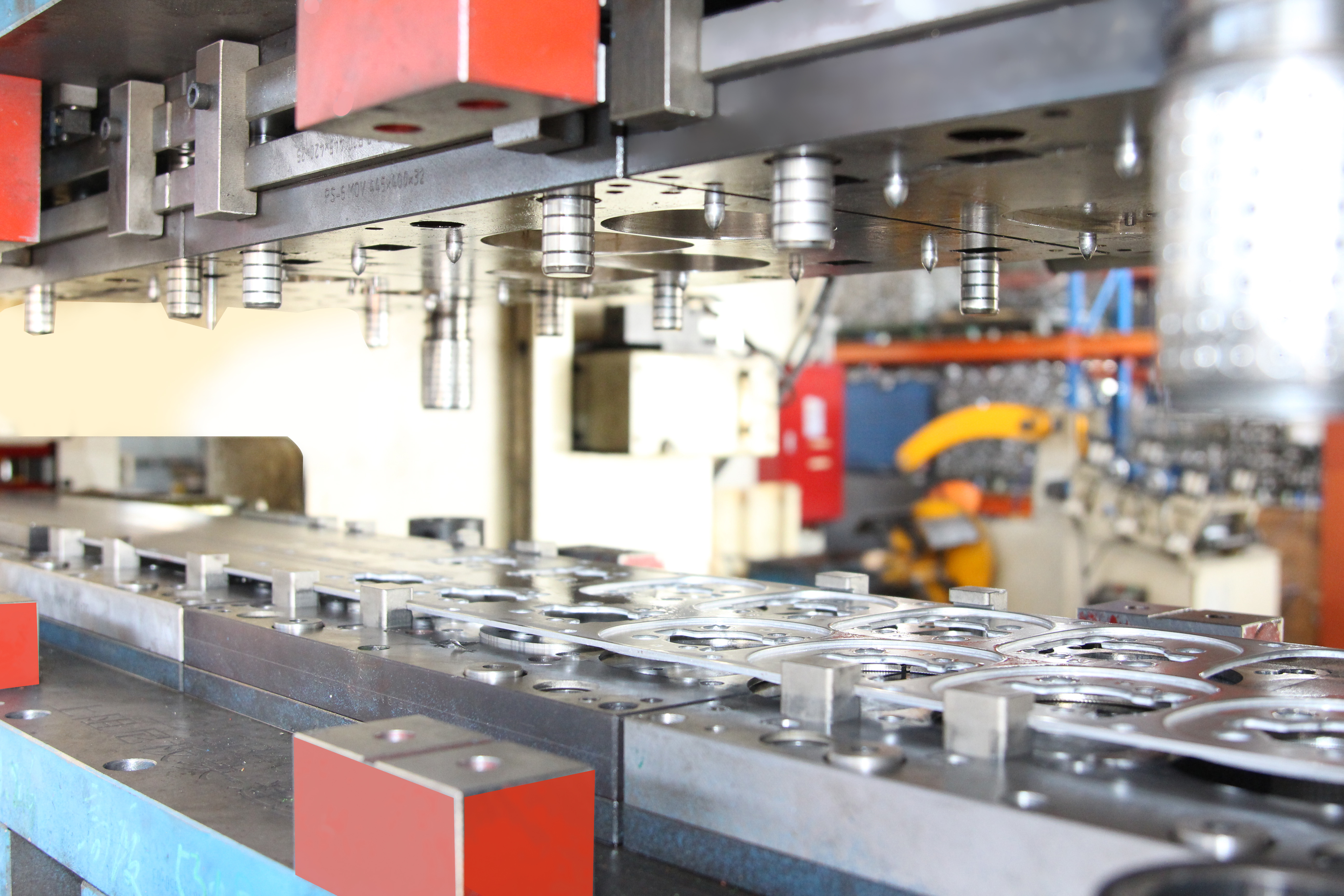
Imagine a stamping press running at full speed, spitting out intricate parts every few seconds. That’s the world of progressive die stamping. In progressive stamping, a long strip of metal moves through a die set with multiple stations. Each station performs an operation—piercing, forming, bending, or trimming—so that with every press stroke, a finished part drops out the end. This approach is ideal for high-volume runs of complex parts, where tight tolerances and low per-part costs matter most.
But what if your part is flat and simple? Compound die stamping brings efficiency for basic, flat shapes. Here, multiple operations—like cutting and punching—happen in a single press stroke. This keeps tooling simpler and costs lower, but it’s not suited for complicated geometries or very high output.
For large or complex parts, especially those needing multiple forming steps, transfer stamping is your go-to. In this method, parts are moved—mechanically or manually—between stations, each performing a specific operation. It’s more flexible for intricate shapes and can handle parts that progressive dies can’t, but comes with higher setup and maintenance needs.
| Die Type | Best For | Typical Features | Setup Complexity | Changeover Agility | Scrap Control | Scalability | Tolerance Range |
|---|---|---|---|---|---|---|---|
| Progressive Die | High-volume, complex parts | Multiple operations, intricate shapes | High | Low (dedicated setup) | Good (optimized strip layout) | Excellent for large runs | Tight |
| Compound Die | Simple, flat parts | Cutting & punching in one stroke | Low | High (quicker to swap) | Efficient for flat shapes | Best for low to mid runs | Moderate to tight |
| Transfer Die | Large or intricate parts | Multiple forming steps, deep draws | High (transfer system needed) | Moderate (complex setup) | Good with proper design | Versatile (short or long runs) | Moderate to tight |
When to Select Stage Tooling or Secondary Operations
Not every project justifies a full progressive or transfer die. For prototypes, development, or low-volume runs, stage tooling—where each operation is performed in a separate, often simpler die—can be cost-effective. It’s also easier to tweak as designs evolve. Secondary operations like fineblanking or coining may be added to achieve ultra-smooth edges or precise features when standard dies can’t deliver the needed results.
How Part Geometry and Volume Influence Die Choice
Here’s a practical approach: sketch your process flow—pierce, form, flange, trim—so you stabilize the material before tackling tight features. If your part requires complex bends, deep draws, or a combination of operations, progressive or transfer dies are likely best. For flat washers or simple brackets, compound dies or stage tooling can save cost and speed up changeovers. Always weigh your annual volume, tolerance bands, and budget against the die’s complexity and cost.
-
Red Flags for Die-Type Mismatch:
- Excessive rework or secondary machining
- Unmanageable burr or inconsistent edge quality
- High scrap rates or material waste
- Frequent die maintenance or downtime
- Difficulty holding critical tolerances
Early process planning and the right die choice help you avoid late-stage surprises during tryout and PPAP.
Safety note: Whenever you’re designing for transfer stamping or any process involving moving parts, always include interlocks and guarding in your plan. Adhere to your shop’s safety SOPs and applicable standards to protect both operators and equipment.
Ready to dive deeper? Next, we’ll explore how design-for-manufacturability (DFM) and smart tolerancing rules can help you prevent rework and maximize tool life—no matter which die you choose.
DFM and Tolerancing Rules That Prevent Rework
Ever had a metal stamped part crack at the bend or noticed holes that distort after forming? These issues are more common than you might think—and nearly always trace back to a few critical design-for-manufacturability (DFM) missteps. Let’s walk through the essential rules that will help you design robust, cost-effective parts and avoid the headaches of rework or tool damage in your die and stamping projects.
Essential DFM Rules for Sheet Metal Parts
Sounds complex? It does not have to be. By following a handful of proven guidelines for sheet metal stamping design, you can dramatically improve manufacturability, reduce scrap, and extend the life of your stamping die components. Here are the core principles every engineer should keep in their spec sheet:
| Operation | Typical Design Aim | Tolerance Strategy | Notes by Material Family |
|---|---|---|---|
| Piercing (Holes/Slots) | Clean edges, minimal burr, no distortion | Minimize tight tolerances unless functionally required | Holes: ≥ material thickness (Al); ≥ 2x thickness (Stainless); Place ≥ 2x thickness from edges |
| Bending | No cracks, consistent angle, minimal springback | Use standard radii; avoid sharp corners | Aluminum (soft): radius ≥ thickness; Aluminum (T6): 1.5–2x thickness; Steel: 1–2x thickness; Stainless: 2x thickness |
| Notches/Tabs | Prevent tearing, avoid unsupported features | Maintain generous radii at internal corners | Add relief notches at bend intersections; avoid tabs smaller than material thickness |
| Ribs/Beads | Increase stiffness without excessive thinning | Allow for material thinning at feature | Depth ≤ 3x material thickness for embosses; beads improve panel rigidity |
| Hems | Edge safety, appearance, joint strength | Use open or teardrop hems for hard/brittle materials | Apply same bend radius rules; avoid closed hems on brittle alloys |
“Specify hole diameters ≥ material thickness unless validated by trials.”
“Align bends with rolling direction cautiously; test for cracking on HSS.”
“Apply tighter GD&T only on functional datums; relax cosmetic regions.”
Tolerancing Strategy by Operation
When you design metal stamping components, it’s tempting to call out tight tolerances everywhere. But did you know that overly tight tolerances are a leading cause of unnecessary cost and scrap? For most tooling dies, reserve tight geometric dimensioning and tolerancing (GD&T) for features that matter—like mounting holes or datum surfaces. For cosmetic regions or non-critical features, looser tolerances are not only acceptable but recommended. This approach means fewer die stations, less rework, and longer tool life.
Designing for Consistent Material Flow
Imagine forming a stamped steel sheet that needs to bend, hold shape, and look good. Consistent material flow is key. Place holes and cutouts at least 4x material thickness away from bend lines to prevent distortion; add radiused corners to cutouts to avoid stress concentrations. For ribs and beads, expect some material thinning—so adjust your design or consult with your manufacturer on acceptable limits. And always check how grain direction aligns with your bends: bending perpendicular to the grain is strongly recommended to minimize the risk of cracking, especially with tight radii. Bending parallel to the grain should be avoided whenever possible.
- Tight internal corners (risk of cracking)
- Unsupported tabs or small features (prone to bending or breakage)
- Overly small piercings (accelerate punch wear)
- Holes/cutouts too close to bends or edges (distortion, tearing)
- Non-standard sheet thicknesses (higher cost, longer lead)
- Unnecessary tight tolerances (drives up cost and rework)
By following these metal stamping design rules, you’ll notice smoother production, fewer surprises during tryout, and more robust parts right out of the press. Next, we’ll explore how digital die design and simulation help optimize these choices before any steel is cut, ensuring your DFM strategies pay off in real-world manufacturing.

Die Design With CAD CAM and Forming Simulation
When you look at a perfect stamped part, you might wonder: how did engineers get it right—before any steel was cut? The answer lies in a modern, digital workflow that blends CAD, CAM, and forming simulation to take your project from blueprint to production-ready metal die with fewer surprises and less scrap. Let’s walk through the process, step by step, and see how each stage builds confidence and quality into your stamping die design.
From Part Spec to Strip Layout: Planning for Success
It all starts with a careful analysis of your part’s geometry, material, and tolerances. Imagine you’ve received a new part print—your first move isn’t to jump into 3D modeling, but to study the requirements and ask: What operations will this part need? Which features might cause trouble during forming or cutting?
Next comes the strip layout. This is the roadmap for how your raw sheet will travel through the die, station by station. The goal: minimize material waste, ensure stable part formation, and optimize the number of operations. A smart strip layout can save you significant cost and set the stage for robust progressive stamping die design.
- Part intake and requirements review
- Feasibility and DFM (Design for Manufacturability) assessment
- Process planning and strip layout in CAD
- Forming simulation (virtual tryout)
- Detailed die design (all components modeled)
- CAM programming for die manufacturing
- Physical tryout and correlation with simulation
- Release to production (with documentation)
When to Apply Forming Simulation—and Why It Matters
Sounds technical? It’s actually a huge time and cost saver. Before any metal is machined, forming simulation lets you test the die virtually. Using specialized software, engineers simulate how the sheet will behave as it’s formed—predicting thinning, wrinkling, splits, and springback. This digital tryout helps spot trouble areas early, so you can tweak the design before committing to expensive tool steel.
Forming simulation is especially valuable for complex parts or high-strength materials. It allows you to:
- Check if the part can be formed without defects
- Optimize draw beads, addendum surfaces, and binder forces
- Predict and reduce springback for better dimensional control
- Evaluate multiple process concepts quickly
Use simulation early to avoid late-stage steel changes.
By catching issues before the die is built, you reduce the number of physical tryouts, shorten lead times, and boost the reliability of your metal stamping die design.
Using Simulation Outputs to Refine Die Geometry
What do you do with all the simulation data? You’ll want to track key outputs—like thinning maps, strain distributions, and springback vectors. During physical tryout, compare these predictions to real-world measurements. If the part shape repeats within your tolerance zones and no major defects appear, you’ve achieved qualitative convergence.
If not, loop the results back into your CAD model: adjust draw beads to control material flow, tweak addendum surfaces for smoother forming, or modify binder forces to balance pressure. This iterative approach is the backbone of modern tool and die manufacturing.
To keep everything organized and traceable, integrate your workflow with PLM (Product Lifecycle Management) and PPAP (Production Part Approval Process) documentation. Version control and a lessons-learned library are invaluable—imagine being able to review past die launches to avoid repeating mistakes.
By leveraging CAD, CAM, and simulation at every stage, you set up your die manufacturing process for success. And as you move from digital validation to the physical tryout, you’ll be ready to correlate results and fine-tune your tooling for stable, repeatable production.
Next, we’ll explore how to choose the right press and automation strategies to get the most from your new die—keeping throughput high and changeovers low.
Press Selection Tonnage and Smart Automation
When you’re ready to bring a new die and stamping project to life, choosing the right press tool and automation setup can make or break your throughput—and your bottom line. Sounds complex? It doesn’t have to be. Let’s break down the essentials so you can confidently select a stamping die machine that matches your part, process, and production goals.
Press and Tooling Compatibility Essentials
Imagine you’ve invested in a state-of-the-art die, but your press can’t deliver the required force or doesn’t fit the die set. That’s a scenario you want to avoid. The first step is understanding the main variables that define press compatibility for any sheet metal stamping machine:
- Material type and thickness: Harder or thicker materials demand higher tonnage and energy.
- Part envelope and feature count: Larger or more intricate parts require a bigger bed size and may need more die stations.
- Forming severity: Deep draws or complex bends increase the load on the die press.
- Shear/bend allowances and lubrication: These impact both tonnage and part quality.
- Bed size and shut height: The press bed must accommodate the die’s footprint and allow full closure without interference.
Presses come in mechanical, hydraulic, and servo types. Mechanical presses offer speed for simpler, shallow parts, while hydraulic presses provide flexibility for deep, complex forms. Servo presses blend speed and control, making them ideal for a range of applications.
Press Selection Worksheet:
Material: _______
Thickness: _______
Part Envelope (LxWxH): _______
Number of Stations: _______
Estimated Peak Tonnage (see formula below): _______
Bed/Shut Height: _______
Feed Direction: _______
Automation Needs: _______
Safety Interlocks: _______
Tonnage and Energy Considerations Simplified
Ever wondered how much force your press dies need to deliver? Calculating required tonnage isn’t just about the biggest punch—it’s about the sum of all operations in your die. Here’s a simplified approach, adapted from industry best practices (The Fabricator):
- For blanking and piercing: Tonnage = Perimeter x Material Thickness x Shear Strength
- For drawing operations: Use the ultimate tensile strength instead of shear strength.
- Add load from all stations, including scrap cutting, pad pressures, and auxiliary functions.
Don’t forget energy—having enough tonnage is useless if the press can’t deliver it over the full stroke. Always check that your die for press is balanced and fits within the press’s rated bed area. For complex progressive stamping press setups, use a progression strip layout to balance loads and avoid off-center stresses.
Automation and IIoT to Stabilize Throughput
Want to boost consistency and reduce manual handling? Modern sheet metal stamping machines often integrate automation options like feed lines, coil handling, robots, and end-of-arm tooling. These not only increase speed but also minimize misfeeds and operator risk. Smart sensors and IIoT/Industry 4.0 tech take it further—enabling real-time monitoring, die protection, and predictive maintenance for higher OEE (Overall Equipment Effectiveness).
| Automation Option | Typical Benefits | Potential Caveats |
|---|---|---|
| Feed Lines/Coil Handling | Consistent material delivery, fewer jams | Requires space, setup calibration |
| Robotic Handling | Reduced manual labor, stable cycle times | Higher upfront cost, programming required |
| End-of-Arm Tooling | Customizable for part geometry | Needs periodic adjustment |
| IIoT Sensors/Die Protection | Real-time alerts, condition monitoring | Integration complexity, training needed |
-
Safety Must-Haves for Every Press Setup:
- Lockout-tagout procedures
- Light curtains and presence sensors
- Two-hand controls
- Die safety blocks
- Physical guarding and signage
Always reference relevant safety standards, such as OSHA 1910 Subpart O for machinery and machine guarding, and ANSI B11.1 for mechanical power presses. These guidelines help ensure your stamping die machine setup is both productive and safe.
By carefully matching your die, press, and automation strategy, you’ll notice smoother changeovers, higher part quality, and fewer unplanned stoppages. Next, we’ll explore how material strategies for steel and aluminum further influence your process window and tool life.
Material Strategies for Steel and Aluminum
Ever wondered why some stamped steel parts hold their shape perfectly, while others—especially aluminum—seem to spring back or pick up surface marks? Choosing the right material strategy is crucial for successful die and stamping operations. Let’s break down the unique behaviors of steel and aluminum, and walk through practical ways to minimize defects and extend tool life.
Strategies for Steel Materials
Steel is the classic choice for most stamped metal components because of its predictable formability and robust performance. But even within steel, grades vary: low-strength steels (LSS) and deep drawing steels (DDS) are more forgiving, while higher-strength grades demand tighter process control. Steel’s higher Young’s modulus means it resists springback, so formed shapes tend to stay put. It also holds up well to complex draws and can tolerate higher forming forces without splitting.
- Bead tuning: Use draw beads and addendum features to control material flow and prevent wrinkles or splits.
- Robust punch support: Ensure die rigidity to avoid misalignment and premature wear, especially with high-strength grades.
- Controlled blankholder pressure: Adjust pressure to balance stretching and prevent surface defects.
- Lubrication: Choose heavier-duty compounded oils or macroemulsions for tough draws, and ensure even application to reduce galling and scoring.
- Cleanliness: Keep incoming stock free from scale, oxides, and grit to avoid surface scratches and abrasive wear.
Strategies for Aluminum Panels
Aluminum stamping brings its own set of challenges. Aluminum alloys, popular for lightweighting in automotive and aerospace, have lower Young’s modulus and unique strain hardening behavior. This means higher springback—so the part might not match the die contour after release. Aluminum also has lower deformation capacity after necking, making it more sensitive to splits and localized thinning.
- Larger radii and gentle bends: Use generous bend radii to avoid cracking and accommodate springback. For aluminium sheet stamping, this is even more important.
- Optimized lubrication: Select lubricants with good boundary film and EP (extreme pressure) additives. Lighter-duty vanishing oils may work for shallow forms, but compounded oils are better for deep draws (The Fabricator).
- Polished die surfaces: Aluminum is prone to galling and surface marking. Keep die surfaces highly polished and clean to reduce cosmetic defects.
- Vacuum handling: Since aluminum isn’t magnetic, use vacuum systems for part transfer rather than magnetic pick-and-place.
- Process window control: Because aluminum forms differently at each stage, use simulation or trials to dial in draw beads, restraining forces, and addendum geometry.
Reducing Wear and Maintaining Surface Quality
Tool and part surface quality go hand in hand. For both steel and aluminum stamping, insufficient lubrication or dirty materials can lead to galling, scratches, and premature die wear. Here’s a quick checklist of proven countermeasures:
- Choose lubricants matched to material and forming severity
- Filter recirculating fluids to remove metal particles and oxides
- Maintain die coatings and surface finishes—repolish as needed
- Adjust tool clearances for each material type
- Inspect incoming material for contamination or heavy mill oil
Match lubrication and surface finish to material to slow wear and stabilize part release.
Still deciding between steel and aluminum for your next aluminum stamping or stamped steel project? Always consult supplier datasheets for specific forming limits and recommended practices. Keeping these strategies in mind will help you avoid common defects—like cracks, wrinkles, or surface strains—and ensure your die and stamping process delivers high-quality results every time.
Up next, we’ll walk through how to stabilize your process window from the first die tryout to first-article approval, ensuring your stamping runs are both robust and repeatable.
From Tryout to First Article Approval
When you finally reach the press with a new set of stamping dies, the journey from first hit to stable production is anything but a straight line. Imagine standing at the press, ready for the first cycle—will the part meet spec, or will you face splits, burrs, or misalignment? Sounds stressful? With the right process, you can turn uncertainty into confidence and ensure your stamping manufacturing process is robust from day one.
Die Setup and Tryout Essentials
Every successful stamping process of sheet metal begins with a meticulous die setup. This isn’t just about bolting the die into the press—it’s about eliminating every variable that could affect part quality or tool life. Here’s how to get it right:
Die Setup Checklist:
- Verify all fasteners and clamps are tight and secure.
- Inspect and clear lube lines and ensure proper lubrication flow.
- Confirm sensors are installed, connected, and functioning.
- Set and check shut height to match die and press specs.
- Check tooling alignment and parallelism of die sets.
- Ensure scrap clearance paths are unobstructed.
- Run a safe dry-cycle (no material) to check for interference or abnormal sounds.
During tryout, don’t rush. Use the press’s inching mode for slow, controlled movement. This allows for careful observation and adjustment—crucial for preventing die damage and catching issues before they escalate (Henli Machine).
Tryout Checklist:
- Record all press parameters (tonnage, speed, stroke, lube type).
- Evaluate first parts for splits, wrinkles, and surface defects.
- Check burr direction and edge quality.
- Measure springback at key datums; compare to simulation where available.
- Document steel-safe areas for potential adjustments.
Remember, initial tryouts are about learning. Expect to make small tweaks—shim adjustments, sensor recalibration, or minor spotting (surface contact correction) to ensure even pressure distribution across the die stamp.
First-Article Inspection and Correlation
Once the die produces parts that look promising, it’s time for first-article inspection (FAI). This step is your bridge between development and stable production. The FAI confirms that the process, tooling, and part all meet design intent—and that your measurement methods are reliable.
First-Article Inspection Checklist:
- Confirm all critical dimensions to GD&T datums.
- Inspect cosmetic zones for surface marks or indentations.
- Check for thickness thinning in formed areas.
- Assess hole quality (diameter, location, burrs).
- Validate functional fit with mating components.
- Reference specific tolerances from the drawing or standards where required.
It’s best practice to submit 3–5 parts for FAI, measuring every dimension called out on the drawing. Be sure to document the measurement methods and equipment used, including calibration status and any measurement uncertainty. If discrepancies arise, work collaboratively to resolve whether the issue lies in the tooling, process, or inspection method. Don’t forget: features close to tolerance limits require special scrutiny, as measurement uncertainty can tip them out of spec.
Stabilizing the Process Window
Achieving a good first article is only half the battle. The next challenge is stabilizing the process window—ensuring that every part coming off the press meets spec, shift after shift. This means identifying and controlling the variables most likely to cause defects or drift.
-
Common Defects & Correction Levers:
- Splits/cracks: Reduce forming severity, adjust draw beads, check material grade.
- Wrinkles: Increase blankholder force, optimize lube, adjust addendum geometry.
- Burrs: Resharpen or replace cutting edges, adjust die clearance.
- Uneven stretching or thinning: Tweak forming sequence, review die spotting and shimming.
- Surface marks/indentations: Clean die surfaces, improve lubrication, inspect incoming material.
For every defect, there’s a corresponding lever—whether it’s a tooling adjustment, process parameter, or material change. Keep a log of all changes and observations during tryout and early production; this record is invaluable for future troubleshooting and continuous improvement of your stamping tooling.
Safety reminder: Always run the press at reduced speed during first hits, with all guards and safety devices in place. Never bypass interlocks or sensors—operator safety is paramount, especially when working with new or modified die sets.
By following these structured procedures and checklists, you’ll transform the uncertainty of first hits into the confidence of stable, repeatable production. Mastering this transition is what separates reactive shops from best-in-class stamping and pressing operations. Next, we’ll examine how procurement and maintenance strategies can help you sustain this performance, keeping costs low and uptime high as you scale up production.
Procurement Costing and Maintenance Planning
When you’re weighing options for a new die and stamping program, the right questions can make the difference between a cost-effective launch and years of hidden headaches. Ever wondered why some stamping die manufacturers deliver consistent, low-cost parts, while others struggle with downtime or quality surprises? Let’s break down the real drivers of total cost, the essentials of maintenance planning, and the supplier evaluation criteria that make tool & die investments pay off for the long haul.
Cost Drivers for Dies and Production
Imagine you’re pricing a new stamping project—what makes the biggest impact on your bottom line? The answer isn’t just the price tag on the die tool. Here are the main cost factors to consider:
| Decision Factor | What to Ask | What Good Looks Like |
|---|---|---|
| Production Volume | What’s the estimated annual usage? | High volumes spread tooling costs; low volumes may favor stage tooling or modular dies. |
| Part Complexity | How many bends, forms, or features? | Simpler parts = lower die cost; complex features drive up die and process costs. |
| Quality Targets | What tolerances and finishes are required? | Critical tolerances require more robust tool & die solutions and higher inspection costs. |
| Speed-to-Market | How urgent is the launch? | Short lead times may require premium pricing or expedited die manufacturing. |
| Change Frequency | How likely are design or volume changes? | Flexible dies or modular tooling reduce risk of costly rework. |
| Material Choice | Which alloys and thicknesses? | Common steels and aluminum are most cost-effective; exotic alloys raise both die and part costs. |
| Secondary Operations | Are finishing or assembly steps needed? | Integrated operations in the die lower total cost; external steps add expense. |
For most stamping die manufacturing projects, investing in robust, well-designed tooling up front pays off in fewer breakdowns, less scrap, and lower long-term maintenance costs. Always balance initial investment with expected production life and changeover needs.
Maintenance Planning and Tool Life
Ever had a line go down because a punch broke, or been forced to ship parts with a quality hold? Maintenance isn’t just a back-room chore—it’s a core part of your risk and cost structure. A proactive maintenance plan for your tool die and die tool assets reduces downtime, improves part quality, and extends tool life (The Phoenix Group).
Copy-Ready Maintenance Plan Template:
- Critical spares list (punches, inserts, springs, sensors)
- Preventive maintenance cadence (e.g., cycles, hours, or lot size)
- Coating strategy (surface treatments, re-coating intervals)
- Sensor checks (functionality, calibration, replacement intervals)
- Lubrication SOP (types, frequency, application method)
- Revision control (document all changes, repairs, and upgrades)
Collaborate with your tool & die maker to tailor this plan to your specific dies manufacturing environment. Use a work order system to document and track every repair or adjustment—this builds a history that helps predict wear and optimize future maintenance.
Supplier Evaluation Criteria
Choosing the right stamping die manufacturers isn’t just about price or delivery. You’ll notice the best partners have a proven system for quality, capacity, and risk management. Here’s a simple sourcing rubric to guide your selection:
- Process expertise (track record in your part type and industry)
- CAE capability (simulation and DFM support)
- Metrology (in-house inspection and documentation)
- Change control (clear procedures for engineering changes)
- Traceability (part and material lot tracking)
- After-sales support (spare parts, troubleshooting, training)
For a deeper evaluation, consider these questions:
- Does the supplier have a certified quality management system (e.g., ISO 9001)?
- Can they demonstrate on-time delivery and low scrap rates?
- Do they provide clear PPAP deliverables and inspection reports?
- Are best practices from sources like SME, The Fabricator, or NADCA referenced in their process standards?
Tip: When reviewing stamping die manufacturing partners, request maintenance and quality documentation, and ask for sample work orders or inspection reports. This transparency is a strong indicator of a reliable tool & die maker.
By focusing on these cost, maintenance, and sourcing criteria, you’ll set your die and stamping program up for predictable costs, high uptime, and consistent quality. Next, we’ll look at how to choose automotive die partners—where CAE-driven support and global standards become even more critical.

What to Look for in a Die Maker
Automotive Die Partner Checklist
When you need automotive stamping dies that hit the mark on quality, speed, and support, the right partner makes all the difference. Sounds overwhelming? It doesn’t have to be. By focusing on a few key areas, you can quickly build a shortlist of die makers who will deliver reliable sheet metal pressings—from the first prototype to full-scale production. Here’s a practical checklist to guide your search:
- Certification (IATF 16949, ISO 9001)
- CAE/formability analysis (virtual tryout, simulation-driven design)
- Simulation-to-tryout correlation (proven ability to match digital results with real-world parts)
- PPAP support (documentation and process validation)
- Metrology (advanced measurement and inspection)
- Launch support (engineering assistance during ramp-up and changeovers)
- Global OEM experience (track record with major automakers)
Early collaboration with a CAE-enabled die maker reduces steel changes and accelerates PPAP.
What to Expect from a CAE-Enabled Supplier
Imagine you’re launching a new vehicle platform. Wouldn’t it be reassuring to know your stamping die factory can spot issues—like springback or thinning—before the first tool is cut? That’s where CAE (Computer-Aided Engineering) comes in. Suppliers who leverage CAE and forming simulation can:
- Predict and resolve formability issues virtually, cutting down physical tryout loops
- Optimize die geometry for better material flow and dimensional accuracy
- Shorten lead times and reduce tooling costs by minimizing late-stage changes
- Provide robust documentation for PPAP and ongoing quality assurance
For example, Shaoyi Metal Technology offers IATF 16949-certified automotive stamping dies, advanced CAE simulation, and end-to-end support—from in-depth structural reviews to rapid prototyping and mass production. Their process is designed to deliver precision-engineered sheet metal pressings trusted by global OEMs. When benchmarking suppliers, look for this level of transparency and technical depth, especially for complex or high-volume programs.
Comparing Automotive Die Partners
| Supplier | Certification | CAE/Simulation | Simulation-to-Tryout Correlation | PPAP & Metrology | Launch Support | Global OEM Experience |
|---|---|---|---|---|---|---|
| Shaoyi Metal Technology | IATF 16949 | Advanced CAE, Formability Analysis | Yes (proven digital-to-physical match) | Comprehensive (full PPAP, in-house metrology) | Yes (from prototyping to mass production) | Yes (30+ global brands) |
| Supplier B | ISO 9001 | Basic CAD, limited simulation | Partial (occasional correlation) | Standard (PPAP on request) | Limited (mostly production phase) | Some (regional OEMs) |
| Supplier C | None/Unknown | No simulation, manual design | No | Minimal (inspection only) | No formal launch support | None |
Note: Always verify supplier capabilities directly, as offerings may change. Use this table as a starting point for deeper discussions and site audits.
From Prototype to Mass Production: The Value of a True Die Partner
So, what is tool and die partnership in the automotive sector? It’s more than just delivering a die—it’s about providing guidance, digital validation, and ongoing support as your needs evolve. The best diemaker will help you navigate every stage of what is die manufacturing—from simulation-driven concept reviews to launch troubleshooting and continuous improvement.
By focusing on CAE-enabled, globally experienced partners, you’ll set your die and stamping program up for fewer surprises, reduced scrap, and faster time-to-market. Ready to move forward? Use the checklist and comparison table above to guide your next supplier interview—and make sure your automotive stamping dies are built for the future.
Frequently Asked Questions about Die and Stamping
1. What is the difference between die-cutting and stamping?
Die-cutting uses a specialized tool to cut materials, much like a cookie cutter, while stamping refers to pressing sheet metal between dies to shape or form it. Stamping often includes multiple operations such as forming, bending, and piercing, making it ideal for producing complex, repeatable metal parts at scale.
2. What is a stamping die and how does it work?
A stamping die is a precision tool made from hardened steel that shapes, cuts, or forms sheet metal into specific parts. It works in a stamping press, where the die and press together convert flat sheet metal into finished components through a series of controlled operations, ensuring high repeatability and dimensional accuracy.
3. Which types of stamping dies are best for high-volume production?
Progressive dies are typically the best choice for high-volume, complex parts because they perform multiple operations in sequence, producing finished parts with each stroke. For simpler or flat parts, compound dies offer efficiency, while transfer dies suit large or intricate parts requiring several forming steps.
4. How do you select the right press and automation for stamping?
Selecting the right press involves matching tonnage, bed size, and shut height to your die and material needs. Automation options like feed lines, robots, and sensors enhance throughput and safety. Always factor in material type, part complexity, and production volume to ensure efficient, safe, and consistent manufacturing.
5. What should you look for in an automotive stamping die supplier?
Look for suppliers with IATF 16949 or ISO 9001 certification, advanced CAE simulation capabilities, and a proven track record in automotive projects. Strong partners offer support from prototyping through mass production, robust PPAP documentation, and the ability to correlate simulation with real-world results, ensuring fewer surprises and faster launches.