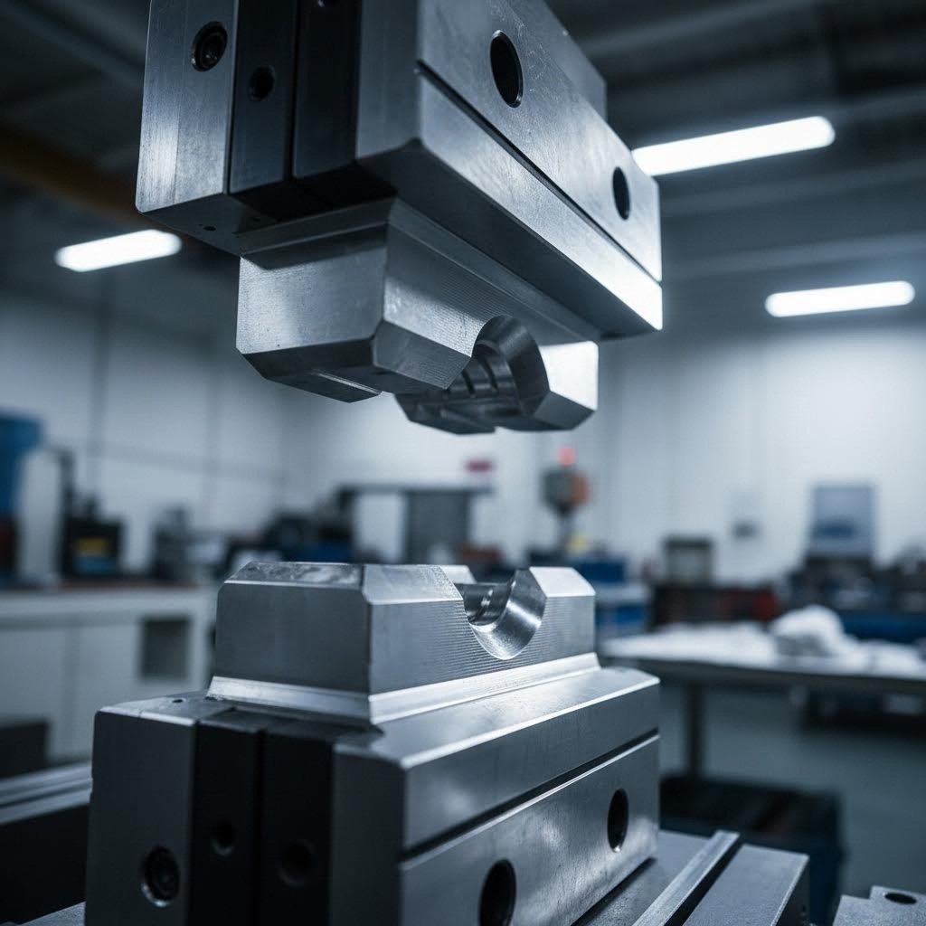
 Small batches, high standards. Our rapid prototyping service makes validation faster and easier —

Flanging Die Design Standards That Eliminate Costly Springback Defects
Understanding Flanging Die Design Standards and Their Manufacturing Impact
Ever wondered what separates a flawless sheet metal flange from one riddled with defects? The answer lies in a set of carefully engineered specifications known as flanging die design standards. These comprehensive guidelines form the backbone of precision metal forming, dictating everything from die geometry and material hardness to tolerance specifications that determine whether your finished parts meet quality requirements or end up as scrap.
Flanging die design standards are documented engineering specifications that govern the geometry, material selection, clearance calculations, and tolerance requirements for dies used in sheet metal flanging operations, ensuring consistent, repeatable, and defect-free flange formation across production runs.
Defining Flanging Die Design Standards in Modern Manufacturing
So, what is flanging exactly? At its core, flanging is a forming operation that bends sheet metal along a curved or straight line to create a protruding edge or rim. Unlike simple bending, flanging involves complex material behavior including stretching, compression, and localized deformation. This complexity demands precise die design parameters to achieve consistent results.
Understanding what is a die is used for provides essential context here. A die serves as the tooling that shapes raw material into finished components through controlled deformation. In flanging applications, the die must account for material springback, work hardening, and geometric constraints that simple forming operations never encounter.
Modern flanging die design standards address these challenges by establishing specific requirements for punch-to-die clearances, typically around 10% to 12% of material thickness for cutting operations according to industry documentation. They also specify die steel hardness ranges, surface finish parameters, and geometric tolerances that ensure repeatable quality.
Why Standardization Matters for Precision Forming
Imagine running production without standardized die specifications. Each toolmaker would interpret requirements differently, leading to inconsistent part quality, unpredictable tool life, and costly trial-and-error during setup. Standardization eliminates this variability by providing a common framework that all parties understand and follow.
The die making process benefits enormously from established standards. When specifications define that die inserts require D2 tool steel at 60-62 Rc hardness, or that stripper clearance around punches should be 5% of material thickness, toolmakers can proceed with confidence. These benchmarks aren't arbitrary; they represent accumulated engineering knowledge refined through decades of production experience.
Standard die specifications also streamline maintenance and replacement. When every component follows documented requirements, replacement parts fit correctly without extensive hand-fitting or adjustment. This reduces downtime and ensures production can resume quickly after routine maintenance.
The Engineering Foundation Behind Flange Formation
Successful flanging die design rests on understanding fundamental forming mechanics. When sheet metal bends, the outer surface stretches while the inner surface compresses. The neutral axis, that critical zone experiencing neither tension nor compression, shifts position based on bend radius, material thickness, and forming method.
The K-factor, representing the ratio of neutral axis location to material thickness, becomes essential for calculating accurate flat patterns and predicting material behavior. This factor typically ranges between 0.25 and 0.50, varying based on material properties, bend angle, and forming conditions. Accurate K-factor determination ensures that finished flanges achieve target dimensions without requiring post-forming correction.
Die geometry specifications translate these engineering principles into physical tooling requirements. Form punch radii, typically specified as three times material thickness when possible, prevent cracking during the forming operation. Die clearances accommodate material flow while preventing wrinkling or buckling. These parameters work together to create flanges that meet dimensional requirements while maintaining structural integrity throughout the formed region.
Fundamental Forming Operations Behind Flanging Die Design
Now that you understand what flanging die design standards encompass, let's dig into the mechanical principles that make these standards necessary. Every flanging operation involves complex material behavior that differs significantly from basic bending or cutting. When you grasp how metal actually moves during flange formation, the engineering rationale behind specific die design requirements becomes crystal clear.
Core Forming Mechanics in Flanging Operations
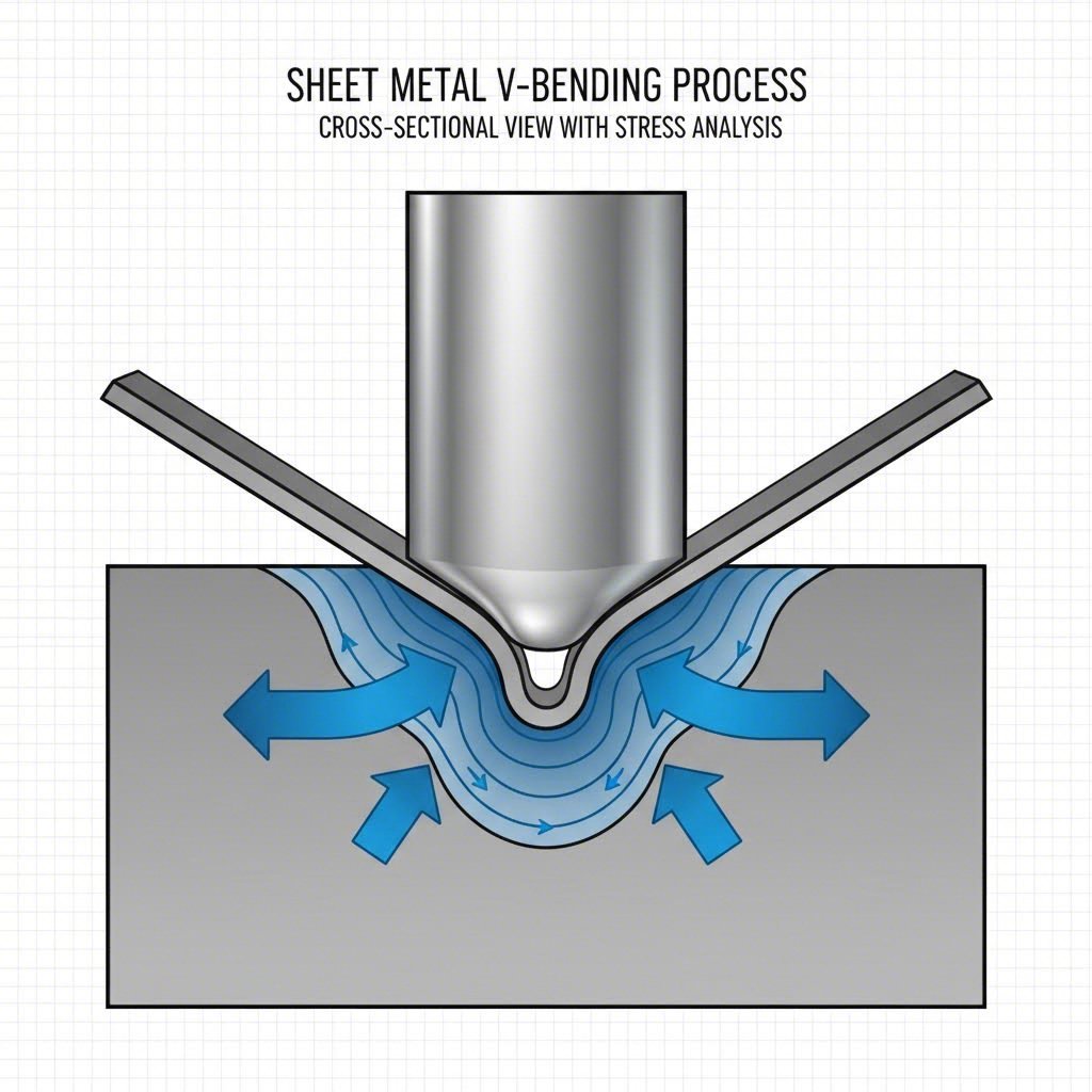
Picture what happens when a punch forces sheet metal into a die cavity. The material doesn't simply fold like paper. Instead, it undergoes plastic deformation where fibers stretch, compress, and flow based on their position relative to the forming tools. This forming operation involves stress states that vary dramatically across the workpiece.
During any flanging process, the metal experiences what engineers call plane strain conditions. The material stretches in one direction, compresses in another, and remains relatively unchanged in the third dimension along the bend line. Understanding this metal forming process helps explain why die clearances, punch radii, and forming speeds all require careful specification.
The forming process also generates significant friction between the sheet and tooling surfaces. This friction influences material flow patterns and affects the force requirements for successful forming. Die designers must account for these interactions when specifying surface finishes and selecting lubricants. In some specialized applications, rubber pad forming offers an alternative approach where a flexible pad replaces rigid tooling, allowing complex shapes with reduced tooling costs.
How Metal Behaves During Flange Formation
When sheet metal bends around a flange line, the outer surface stretches while the inner surface compresses. Sounds simple? The reality involves several competing phenomena that make flanging far more complex than basic bending operations.
First, consider thickness variation. As material stretches on the outer radius, it thins. Compression on the inner radius causes thickening. These thickness changes affect final dimensions and must be anticipated during die design. The neutral axis, where neither tension nor compression exists, shifts position based on bend radius and material properties.
Second, work hardening occurs as plastic deformation progresses. The material becomes stronger and less ductile with each increment of strain. This progressive hardening influences the force required to complete the forming operation and affects springback behavior after the punch retracts.
Third, residual stresses develop throughout the formed region. These internal stresses, locked into the part after forming, determine how much the flange springs back when released from the die. Understanding this behavior is crucial for designing dies that produce accurate final dimensions. Similar principles apply in metal forming and coining operations, where controlled plastic flow creates precise features.
Stretch vs Shrink Flanging Fundamentals
Not all flanging operations behave the same way. The geometry of the flange line determines whether material primarily stretches or compresses during formation. This distinction fundamentally affects die design requirements and potential defects.
The different types of forming operations in flanging include:
- Stretch Flanging: Occurs when forming a flange along a convex curve or around the perimeter of a hole. Material on the flange edge must stretch to accommodate the increased perimeter length. This operation risks edge cracking if the material lacks sufficient ductility or if the stretch ratio exceeds material limits. Die design must incorporate generous radii and appropriate clearances to distribute strain evenly.
- Shrink Flanging: Happens when forming along a concave curve where the flange edge becomes shorter than the original edge length. Material compresses, creating risk of wrinkling or buckling. Dies for shrink flanging often include features that control material flow and prevent compression-induced defects.
- Edge Flanging: The most common type, forming a straight-line flange along the edge of a sheet. Material bends without significant stretching or shrinking along the flange length. This operation most closely resembles simple bending but still requires careful die design to control springback and achieve dimensional accuracy.
- Hole Flanging: A specialized stretch flanging operation that forms a raised collar around a pre-punched hole. The flanging coefficient, expressed as K = d₀ / Dₘ (pilot hole diameter divided by mean diameter after flanging), determines forming difficulty and cracking risk. Lower K values indicate more severe forming conditions.
Each flanging type requires distinct die design approaches because the stress states and material flow patterns differ substantially. Stretch flanging dies incorporate larger punch radii and may require multiple forming stages for severe geometries. Shrink flanging dies often feature pressure pads or draw beads that control material flow and prevent buckling. Edge flanging dies focus primarily on springback compensation and dimensional consistency.
The engineering rationale becomes clear when you consider failure modes. Stretch flanging fails by cracking when tensile strains exceed material limits. Shrink flanging fails by wrinkling when compressive stresses cause buckling. Edge flanging typically produces dimensionally inaccurate parts rather than outright failures. Each failure mode demands specific die design countermeasures embedded within flanging die design standards.
Understanding these fundamental forming operations provides the foundation for interpreting the industry standards and specifications covered in the following section, where international frameworks translate these mechanical principles into actionable design requirements.
Industry Standards and Specifications for Flanging Die Compliance
With a solid grasp of flanging mechanics, you're ready to explore the regulatory framework that governs professional die design. Here's the challenge many engineers face: relevant standards are scattered across multiple organizations, each addressing different aspects of the sheet metal forming process. This fragmentation creates confusion when designing dies that must meet multiple compliance requirements simultaneously.
Let's consolidate this information into a practical reference framework you can actually use.
Key Industry Standards Governing Flanging Die Specifications
Several international standards organizations publish specifications relevant to forming dies and sheet metal forming operations. While no single standard covers every aspect of flanging die design, combining requirements from multiple sources provides comprehensive guidance.
International standards such as VDI 3388 or North American industry guidelines establish comprehensive standards for mechanical systems, including pressure-temperature ratings and material specifications that influence die steel selection. ASME Y14.5, for example, provides the Geometric Dimensioning and Tolerancing (GD&T) framework essential for defining precision tooling specifications.
The Deutsches Institut für Normung (DIN) standards, widely adopted across Europe, offer precision-focused specifications known for their exacting quality requirements. DIN standards use metric measurements and provide detailed geometric tolerances applicable to forming dies and metal forming dies used in high-precision applications.
The American National Standards Institute (ANSI) works alongside ASME to establish guidelines covering dimensional specifications and pressure ratings. ANSI standards ensure compatibility and interchangeability across manufacturing systems, which becomes critical when sourcing replacement die components or integrating tooling from multiple suppliers.
For sheet metal forming specifically, ISO 2768 serves as the prevalent standard for general tolerances. This specification maintains the balance between manufacturing costs and precision requirements, providing tolerance classes that manufacturers can reference when designing dies for various application levels.
Translating ASTM and ISO Requirements into Die Geometry
How do these abstract standards translate into physical die specifications? Consider the practical implications for your next forming die project.
ISO 2768 tolerance specifications directly influence die clearance calculations. When your application requires medium tolerance class (ISO 2768-m), die components must achieve tighter dimensional accuracy than coarse tolerance applications. This affects machining requirements, surface finish specifications, and ultimately tooling costs.
ASTM material specifications determine which tool steels qualify for specific applications. When forming high-strength automotive steels, ASTM A681 provides requirements for tool steel grades that ensure adequate hardness and wear resistance. These material standards connect directly to die longevity and maintenance intervals.
The sheet metal forming process itself must comply with dimensional standards that ensure finished parts meet assembly requirements. Dies designed without reference to applicable standards often produce parts that technically form correctly but fail dimensional inspection. This disconnect between forming success and dimensional compliance represents a costly oversight.
| Standards Organization | Key Specifications | Specification Focus | Application Area |
|---|---|---|---|
| ASME | Y14.5, B46.1 | Material requirements, surface texture parameters, pressure-temperature ratings | Die material selection, surface finish specifications for forming operations |
| ANSI | B16.5, Y14.5 | Dimensional tolerances, geometric dimensioning and tolerancing (GD&T) | Die component dimensions, positional accuracy requirements |
| DIN | DIN 6935, DIN 9861 | Metric dimensions, precision tolerances, plastic and metal forming specifications | European manufacturing compliance, high-precision forming dies |
| ISO | ISO 2768, ISO 12180 | General tolerances, cylindricity specifications, geometric tolerancing | Universal tolerance framework for metal forming dies |
| ASTM | A681, E140 | Tool steel specifications, hardness conversion tables | Die steel grade selection, hardness verification methods |
Compliance Frameworks for Professional Die Design
Building a standards-compliant die requires more than checking individual specifications. You need a systematic approach that addresses material, dimensional, and performance requirements in an integrated manner.
Start with material compliance. Your die steel must meet ASTM specifications for the intended tool steel grade. Verify that hardness values, measured per ASTM E140 conversion tables, fall within specified ranges. Document material certifications and heat treatment records to demonstrate compliance during quality audits.
Next, address dimensional compliance. Reference ISO 2768 for general tolerances unless your application specifies tighter requirements. Critical dimensions affecting formed part quality, such as punch radii and die clearances, may require tolerances beyond general specifications. Document these exceptions clearly in your die design documentation.
Surface finish specifications follow ASME B46.1 parameters. Forming surfaces typically require Ra values between 0.4 and 1.6 micrometers, depending on formed material and surface quality requirements. Polishing directions should align with material flow patterns to minimize friction and prevent galling.
Finally, consider application-specific standards. Automotive sheet metal forming operations often reference IATF 16949 quality management requirements. Aerospace applications may invoke AS9100 specifications. Medical device manufacturing follows FDA quality system regulations. Each industry layer adds compliance requirements that influence die design decisions.
The practical benefit of standards compliance extends beyond regulatory satisfaction. Standardized dies integrate smoothly with existing production systems. Replacement components source easily when specifications reference recognized standards. Quality inspection becomes straightforward when acceptance criteria align with published tolerance classes.
Engineers who master this standards framework gain significant advantages. They specify dies that meet compliance requirements without over-engineering. They communicate effectively with toolmakers using recognized terminology. They troubleshoot forming problems by identifying which standard parameters require adjustment.
With this standards foundation established, you're prepared to explore the specific calculations that translate these requirements into precise die clearances and tolerance specifications.

Die Clearance Calculations and Tolerance Specifications
Ready to translate those industry standards into actual numbers? This is where flanging die design gets practical. Calculating optimal die clearance, selecting appropriate punch-to-die ratios, and specifying tolerances correctly determines whether your flanged parts meet specifications or require costly rework. Let's break down each calculation with the engineering rationale that makes these values work.
Calculating Optimal Die Clearance for Flanging Applications
Die clearance, the gap between punch and die surfaces, fundamentally affects material flow, surface quality, and tool life. Too tight? You'll see excessive wear, increased forming forces, and potential galling. Too loose? Expect burring, dimensional inaccuracy, and poor edge quality on your finished flanges.
For flanging operations, clearance calculations differ from standard die cutting tolerances used in blanking or piercing. While cutting operations typically specify clearance as a percentage of material thickness (often 5-10% per side), flanging requires different considerations because the goal is controlled deformation rather than material separation.
The die process for flanging uses this fundamental relationship: proper clearance allows material to flow smoothly around the punch radius without excessive thinning or wrinkling. For most sheet metal applications, flanging clearance equals material thickness plus an additional allowance for material thickening during compression.
Consider material properties when calculating clearance values:
- Low carbon steel: Clearance typically equals 1.0 to 1.1 times material thickness, accounting for moderate work hardening
- Stainless steel: Requires slightly larger clearance at 1.1 to 1.15 times thickness due to higher work hardening rates
- Aluminum alloys: Use 1.0 to 1.05 times thickness, as these materials flow more readily with less springback
The engineering rationale behind these values relates directly to material behavior during forming. Stainless steel work hardens rapidly, requiring additional clearance to prevent excessive friction and tool wear. Aluminum's lower yield strength and work hardening rate permits tighter clearances without adverse effects.
Punch-to-Die Ratio Guidelines for Different Material Thicknesses
The punch-to-die ratio, sometimes called the die size ratio, determines forming severity and influences defect probability. This ratio compares the punch radius to material thickness, establishing whether a given flanging operation falls within safe forming limits.
Industry experience establishes these minimum inside bend radius guidelines relative to material thickness:
- Low carbon steel: Minimum bend radius equals 0.5 times material thickness
- Stainless steel: Minimum bend radius equals 1.0 times material thickness
- Aluminum alloys: Minimum bend radius equals 1.0 times material thickness
A sheet metal die designed with punch radii smaller than these minimums risks cracking on the outer flange surface. The material simply cannot accommodate the required strain without exceeding its ductility limits. When your application demands tighter radii, consider multiple-stage forming or intermediate annealing to restore material ductility.
The dimensions of a die table also factor into these calculations for production equipment. Adequate table size ensures proper support for the workpiece during forming, preventing deflection that could alter effective clearances. Large flanging operations may require oversized tooling arrangements to maintain dimensional control across the entire formed length.
For deeper formed flanges, punch radii requirements become more generous. Reference data indicates that deeper draws need larger radii at the maximum depth point to prevent localized thinning. Starting from the minimum standard size above calculated requirements, specify radii in standard increments of 0.5mm or 1mm to simplify die construction.
Tolerance Specifications That Ensure Flange Accuracy
Dimensional tolerance specifications bridge the gap between theoretical design and production reality. Understanding which tolerances apply where, and why, prevents both over-specification that increases costs and under-specification that causes quality failures.
When specifying flange angle tolerances, account for material springback variation. Industry data indicates these typical achievable tolerances:
- Sheet metal bend angles: ±1.5° for standard production, ±0.5° for precision applications with springback compensation
- Flange length dimensions: Tolerance stackup depends on distance from datum; expect ±0.5mm for features within 150mm of datum, increasing to ±0.8mm for features 150-300mm from datum
- Wall thickness uniformity: ±0.1mm readily achievable for most low-carbon steels; tighter tolerances to ±0.05mm possible with additional process controls
A die is used to achieve these tolerances through precise geometry control. Key tolerance considerations for your flanging die design include:
- Punch radius tolerance: Hold within ±0.05mm for critical forming surfaces to ensure consistent material flow and springback behavior
- Die cavity clearance tolerance: Maintain within ±0.02mm to prevent variation in formed flange thickness
- Angular alignment: Punch-to-die parallelism within 0.01mm per 100mm prevents uneven flanges
- Surface finish consistency: Ra values between 0.4-1.6 micrometers on forming surfaces reduce friction variation
- Locating feature accuracy: Position pilot holes and locating pins within ±0.1mm to ensure repeatable workpiece positioning
- Springback compensation angle: Overbend allowance typically 2-6° depending on material grade and flange geometry
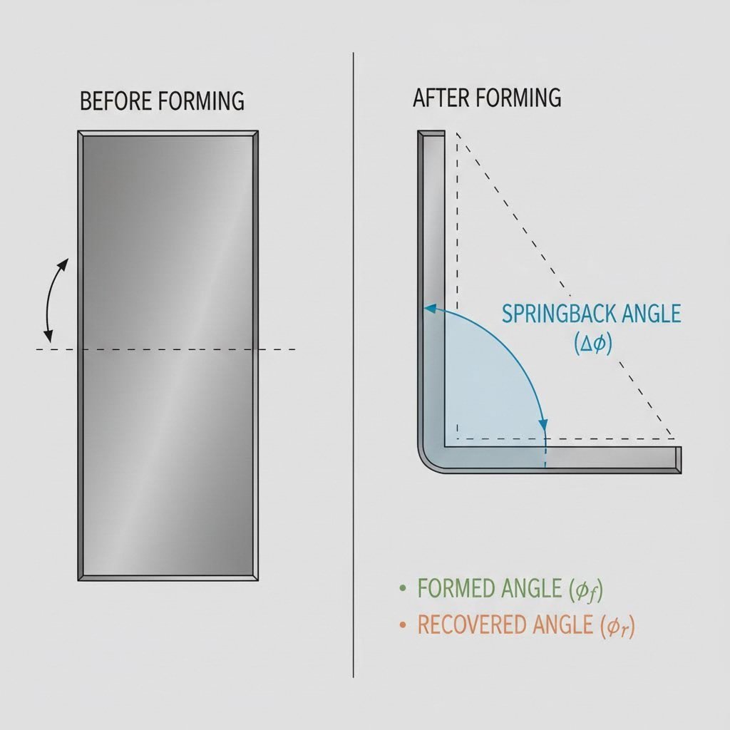
Flange angle specifications directly affect die geometry requirements. When your design calls for a 90° flange, the die must incorporate overbend compensation based on material springback characteristics. Low carbon steel typically springs back 2-3° per side, requiring dies designed to form at 92-93° to achieve the target 90° after elastic recovery. Stainless steel exhibits greater springback at 4-6° per side, demanding correspondingly larger compensation angles.
These tolerance specifications create a comprehensive framework for quality control. Incoming material verification ensures thickness and mechanical properties fall within expected ranges. In-process monitoring confirms forming forces remain consistent, indicating proper die condition and material behavior. Final inspection verifies that formed flanges meet dimensional requirements established during design.
Armed with these clearance calculations and tolerance specifications, you're prepared to address the next critical decision: selecting die materials that maintain these precise dimensions throughout production runs of thousands or millions of parts.
Die Material Selection and Hardness Requirements
You've calculated your clearances and specified your tolerances. Now comes a decision that determines whether those precise dimensions survive the first hundred parts or the first hundred thousand: selecting the right die steel. Material choice directly impacts tool life, maintenance intervals, and ultimately your cost per formed flange. Let's examine how to match die steel grades to your specific flanging requirements.
Selecting Die Steel Grades for Flanging Applications
Not all tool steels perform equally in flanging operations. The forming die experiences repeated stress cycles, friction against sheet material, and localized heat generation during production runs. Your die steel must resist these conditions while maintaining the dimensional accuracy you specified.
According to tool steel application charts, forming and bending dies typically require dimensional tolerance stability combined with wear resistance. The most commonly recommended grades include O1 and D2, each offering distinct advantages for different production volumes and material combinations.
D2 tool steel emerges as the workhorse for high-volume flanging operations. Its high chromium content (approximately 12%) provides excellent wear resistance through abundant carbide formation. For dies processing thousands of parts between sharpenings, D2 delivers the abrasion resistance necessary to maintain dimensional accuracy throughout extended production runs.
O1 oil-hardening tool steel offers better machinability during die construction and adequate performance for moderate production volumes. When your machining die requires complex geometry with tight tolerances, O1's dimensional stability during heat treatment simplifies manufacturing. This grade works well for prototype tooling or lower-volume production where ultimate wear resistance matters less than initial tooling cost.
For applications requiring exceptional toughness alongside wear resistance, consider S1 shock-resistant steel. Swaging dies and applications involving impact loading benefit from S1's ability to absorb repeated stress without chipping or cracking. This grade sacrifices some wear resistance for improved toughness, making it suitable for flanging operations with severe forming conditions.
Hardness and Wear Resistance Requirements
Hardness values determine how well your forming die resists deformation and wear during production. However, higher hardness isn't always better. The relationship between hardness, toughness, and wear resistance requires careful balancing based on your specific application.
Tool steel research confirms that toughness tends to decrease as alloy content and hardness increase. Any given grade of tool steel exhibits greater toughness at lower hardness levels, but reduced hardness negatively affects wear characteristics necessary for acceptable tool life.
For flanging dies, target hardness ranges typically fall between 58-62 Rc for working surfaces. This range provides sufficient hardness to resist plastic deformation under forming loads while retaining adequate toughness to prevent chipping at punch edges or die radii.
The wear resistance equation involves carbide content and distribution. Carbides are hard particles formed when alloy elements like vanadium, tungsten, molybdenum, and chromium combine with carbon during solidification. Greater carbide amounts improve wear resistance but reduce toughness, creating the fundamental tradeoff in die steel selection.
Particle metallurgy (PM) production processes can enhance toughness for a given steel grade through improved microstructure uniformity. When your application demands both high wear resistance and impact tolerance, PM grades offer advantages over conventionally produced steels.
Surface Finish Specifications for Optimal Flange Quality
Die surface finish directly transfers to your formed parts. Beyond aesthetics, surface texture affects friction behavior, material flow patterns, and adhesive wear characteristics during forming operations.
For flanging dies, forming surfaces typically require Ra values between 0.4 and 0.8 micrometers. Polishing direction should align with material flow to minimize friction and prevent galling, particularly when forming stainless steel or aluminum alloys prone to adhesive wear.
Punch radii and die entry radii demand the finest surface finish attention. These high-contact zones experience maximum friction and determine whether material flows smoothly or sticks and tears. Mirror polishing to Ra 0.2 micrometers on critical radii reduces forming forces and extends die life.
| Die Steel Type | Hardness Range (Rc) | Best Applications | Wear Characteristics |
|---|---|---|---|
| D2 | 58-62 | High-volume production flanging, forming abrasive materials | Excellent abrasion resistance, good dimensional stability |
| O1 | 57-62 | Moderate volume production, prototype tooling, complex geometries | Good wear resistance, excellent machinability |
| A2 | 57-62 | General purpose forming dies, lamination dies | Good balance of toughness and wear resistance |
| S1 | 54-58 | Impact-intensive flanging, swaging operations | Maximum toughness, moderate wear resistance |
| M2 | 60-65 | Hot flanging applications, high-speed operations | Red hardness retention, excellent wear resistance at elevated temperatures |
Material-specific die steel guidelines ensure optimal performance across different sheet metal types. When flanging high-strength steels, upgrade to D2 or PM grades to handle increased forming forces without premature wear. Aluminum and copper alloys, while softer, require careful surface finish attention to prevent adhesive buildup that damages both die and workpiece.
Compressive strength, often overlooked in die steel selection, becomes critical for flanging operations involving heavy gauge materials or high forming pressures. Molybdenum and tungsten alloying elements contribute to compressive strength, helping dies resist deformation under load. Higher hardness also improves compressive strength, providing another reason to specify appropriate heat treatment for your application.
With your die material selected and hardness specified, you're equipped to address the forming defects that even well-designed dies can produce. The next section explores springback compensation strategies and defect prevention techniques that transform good die designs into great ones.
Springback Compensation and Defect Prevention Strategies
You've selected your die steel, calculated your clearances, and specified your tolerances. Yet even perfectly manufactured dies can produce defective flanges if springback compensation isn't engineered into the design. Here's the reality: sheet metal has memory. When forming forces release, the material partially recovers toward its original shape. Understanding this behavior and designing dies that anticipate it separates successful flanging operations from costly reject piles.
Engineering Springback Compensation into Die Geometry
Why does springback happen? During metal forming operations, the sheet experiences both elastic and plastic deformation. The plastic portion creates permanent shape change, but the elastic portion wants to recover. Think of bending a metal strip in your hands. When you release it, the strip doesn't stay at the exact angle you bent it to. It springs back partially toward its original flat state.
The degree of springback depends on several factors that your die design must address:
- Material yield strength: Higher strength materials exhibit greater springback because they store more elastic energy during forming
- Material thickness: Thinner sheets experience proportionally more springback than thicker materials formed to the same geometry
- Bend radius: Tighter radii create more plastic deformation relative to elastic, reducing springback percentage
- Bend angle: Springback increases proportionally with bend angle, making 90° flanges more challenging than shallow angles
According to sheet metal die design research, springback compensation requires a disciplined, science-based approach rather than trial-and-error adjustment. Three core methods address this challenge effectively.
The first method involves overbending. Your die intentionally forms the flange past the target angle, allowing elastic recovery to bring the part to specification. For low carbon steel flanges at 90°, dies typically overbend 2-3° per side. Stainless steel requires 4-6° compensation due to higher elastic modulus and yield strength. This approach works well for simple geometries where consistent overbend produces predictable results.
The second approach uses bottoming or coining bending techniques. By applying sufficient tonnage to plastically deform the material throughout its thickness at the bend zone, you eliminate the elastic core that drives springback. Metal forming coining operations essentially override the material's elastic memory through complete plastic flow. This method requires higher press tonnage but delivers exceptional angular accuracy.
The third strategy involves modified die geometry that incorporates springback compensation into punch and die profiles. Rather than simple angular overbend, the tooling creates a compound bend profile that accounts for differential springback across the formed region. This approach proves essential for complex flanging where simple angular compensation produces distorted results.
Preventing Cracking and Wrinkling Through Design Optimization
Springback isn't the only challenge. Forming metal beyond its limits produces cracking, while insufficient material control causes wrinkling. Both defects trace back to die design decisions that either ignore or misunderstand material behavior during the forming operation.
Cracking occurs when tensile strain on the outer flange surface exceeds material ductility. Industry documentation identifies several contributing factors: bend radius too small, bending against grain direction, low-ductility material selection, and over-bending without accounting for material limits.
The die design solution starts with generous punch radii. A punch radius of at least three times material thickness distributes strain across a larger zone, reducing peak tensile stress on the outer surface. For stretch flanging operations where material must elongate significantly, even larger radii may prove necessary.
Wrinkling presents the opposite problem. Compressive forces buckle material along the inside of the formed region, particularly on shrink flanges or long unsupported flange lengths. Die-formed parts with visible wrinkles fail aesthetic requirements and may compromise structural performance in assembly.
Addressing wrinkling requires material flow control through die design features. Pressure pads or blank holders restrain sheet movement during forming, preventing compression-induced buckling. The blank holder force must balance two competing requirements: strong enough to prevent wrinkling, yet not so restrictive that it causes tearing by impeding necessary material flow.
Edge Splitting Solutions and Die Modifications
Edge splitting represents a specific failure mode in stretch flanging operations. As the flange edge elongates, any pre-existing edge defects concentrate strain and initiate cracks that propagate into the formed flange. This defect differs from bend line cracking because it originates at the free edge rather than the maximum stress zone.
Die design solutions for edge splitting focus on material preparation and forming sequence. Burr-free edges on incoming blanks eliminate the stress concentrators that initiate splitting. When burrs exist, orient them toward the inside of the bend where compressive stresses close rather than open potential crack initiation sites.
For severe stretch flanging ratios, consider pre-forming operations that gradually redistribute material before final flanging. Multiple-stage forming allows intermediate stress relief and reduces the strain concentration at any single forming step.
The following troubleshooting reference consolidates common flanging defects with their corresponding die design solutions:
- Springback (angular inaccuracy): Incorporate overbend compensation of 2-6° depending on material grade; use coining bending techniques for precision applications; verify die geometry accounts for material elastic modulus
- Cracking at bend line: Increase punch radius to minimum 3× material thickness; verify bend orientation relative to grain direction; consider pre-annealing for low-ductility materials; reduce flange height if geometry permits
- Wrinkling on flange surface: Add or increase blank holder force; incorporate draw beads or restraining features in die design; reduce unsupported flange length; verify die clearance isn't excessive
- Edge splitting on stretch flanges: Ensure burr-free blank edges; orient existing burrs toward compression side; reduce flanging ratio through multiple forming stages; verify material ductility meets forming requirements
- Surface scratching or galling: Polish die surfaces to Ra 0.4-0.8 micrometers; apply appropriate lubricant for material type; consider die coatings (TiN or nitriding) for adhesive-prone materials
- Thickness variation in formed flange: Verify uniform die clearance; check punch-to-die alignment; ensure consistent blank positioning; monitor material thickness variation in incoming stock
- Dimensional inconsistency between parts: Implement robust locating features; verify repeatability of blank positioning; check die wear patterns; calibrate press brake alignment regularly
The engineering rationale behind these solutions connects directly to the different types of forming behavior discussed earlier. Stretch flanging defects respond to strain distribution strategies. Shrink flanging defects require compression control measures. Edge flanging defects typically trace to springback compensation or dimensional control issues.
Understanding why each solution works empowers you to adapt these principles to unique situations your specific applications present. When standard solutions don't fully address a defect, analyze whether the root cause involves tensile failure, compressive instability, elastic recovery, or friction-related problems. This diagnostic framework guides you toward effective die modifications even for unusual geometries or material combinations.
With defect prevention strategies established, modern die development increasingly relies on digital simulation to validate these compensation approaches before cutting steel. The next section explores how CAE tools verify compliance with flanging die design standards and predict real-world performance with remarkable accuracy.

Design Validation and CAE Simulation in Modern Die Development
You've designed your flanging die with proper clearances, selected the right tool steel, and incorporated springback compensation. But how do you know it will actually work before cutting expensive tooling? This is where computer-aided engineering (CAE) simulation transforms the forming manufacturing process from educated guesswork into predictable engineering. Modern simulation tools let you virtually test your die design against flanging die design standards before committing to physical prototypes.
CAE Simulation for Flanging Die Validation
Imagine running hundreds of forming trials without consuming a single sheet of material or wearing down any tooling. That's exactly what CAE simulation delivers. These digital tools model the complete forming process, predicting how sheet metal will behave as it flows around punches and into die cavities.
According to industry research on sheet metal forming simulation, manufacturers face significant challenges that simulation addresses directly. Material selection and springback create constant dimensional accuracy challenges. Part and process design defects often emerge only during physical try-out when corrections become time-consuming and costly.
CAE simulation validates several critical aspects of your die design:
- Material flow prediction: Visualize how sheet metal moves during forming, identifying potential wrinkling zones or areas where material stretches beyond safe limits
- Thickness distribution analysis: Map thickness changes across the formed part, ensuring no region thins excessively or thickens beyond tolerance
- Springback prediction: Calculate elastic recovery before physical forming, allowing compensation adjustments in the die geometry
- Stress and strain mapping: Identify high-stress zones where cracking risk exists, enabling design modifications before tooling manufacture
- Formability assessment: Compare predicted strains against forming limit diagrams to verify adequate safety margins
The forming manufacturing capabilities of modern simulation extend beyond simple pass-fail analysis. Engineers can investigate countermeasure effectiveness virtually, testing different blank holder forces, lubricant conditions, or die geometry variations without physical trial-and-error cycles.
Integrating Digital Verification with Physical Standards
How does simulation connect to the industry standards discussed earlier? The answer lies in material property validation and dimensional verification against specified tolerances.
Accurate simulation requires validated material models that represent actual sheet behavior. Stamping process research confirms that choosing the right materials is critical, with advanced high-strength steels and aluminum alloys presenting particular challenges due to their forming behavior and springback characteristics.
Your forming processes gain credibility when simulation inputs match physical material testing. This means:
- Tensile testing data: Yield strength, ultimate tensile strength, and elongation values calibrated to actual material batches
- Anisotropy coefficients: R-values that capture directional property variations affecting material flow
- Hardening curves: Strain-hardening behavior modeled accurately for correct force and springback predictions
- Forming limit curves: Material-specific failure boundaries that define safe forming regions
Simulation outputs then verify compliance with dimensional standards. When your specification requires flange angles within ±0.5° or thickness uniformity within ±0.1mm, the software predicts whether your die design achieves these tolerances. Any predicted deviations trigger design refinement before physical tooling manufacture.
The integration of digital verification with IATF 16949 quality management requirements demonstrates how professional die manufacturers maintain standards compliance. This certification framework demands documented validation processes, and CAE simulation provides the traceability and evidence required for quality system audits.
First-Pass Approval Through Advanced Design Analysis
The ultimate measure of simulation effectiveness? First-pass approval rates. When physical dies match simulation predictions, production begins immediately without costly modification cycles.
Stamping process validation research highlights how manufacturers are producing parts from increasingly thin, light, and strong materials that amplify manufacturing challenges. Keeping springback-sensitive parts within expected tolerances requires advanced simulation capabilities that predict real-world behavior accurately.
The virtual try-out approach drastically increases confidence in achieving correct part quality, dimensions, and cosmetic appearance. This confidence translates directly into reduced time and expenses during physical try-out, resulting in shorter time-to-market for new products.
Professional die manufacturers demonstrate these principles in practice. For example, Shaoyi's automotive stamping die solutions leverage advanced CAE simulation to achieve a 93% first-pass approval rate. Their IATF 16949 certification validates that these simulation-driven processes meet automotive industry quality requirements consistently.
What does 93% first-pass approval mean practically? Nine out of ten dies perform correctly without modification after initial manufacture. The remaining cases require only minor adjustments rather than complete redesign. Compare this to traditional approaches where multiple physical try-out iterations were standard practice, each consuming weeks of time and thousands of dollars in material and labor costs.
The engineering team approach at facilities implementing these validation principles follows a structured workflow:
- Digital model creation: CAD geometry defines die surfaces, clearances, and forming features
- Material property assignment: Validated material models based on actual test data
- Process parameter definition: Press speed, blank holder force, and lubrication conditions
- Simulation execution: Virtual forming calculates material behavior and final part geometry
- Results analysis: Comparison against formability limits, dimensional tolerances, and surface quality requirements
- Design optimization: Iterative refinement until simulation predicts compliant results
- Physical manufacture: Die construction proceeds with high confidence in successful performance
This systematic approach ensures that flanging die design standards translate from specification documents into production-ready tooling. The simulation acts as a bridge between theoretical requirements and practical implementation, catching potential issues before they become expensive physical problems.
For engineers seeking validated die solutions backed by advanced simulation capabilities, resources like Shaoyi's comprehensive mold design and fabrication services demonstrate how professional manufacturers implement these digital verification principles at production scale.
With simulation-validated die designs in hand, the final challenge becomes translating these digital successes into consistent production implementation. The next section explores how to bridge the gap between design verification and manufacturing reality through systematic quality control and documentation practices.
Implementing Standards in Production Die Manufacturing
Your simulation results look promising, and your die design meets every specification. Now comes the real test: translating those validated designs into physical tooling that performs consistently on the production floor. This transition from design to die forming reality determines whether your carefully engineered standards compliance delivers actual results or remains theoretical. Let's walk through the practical implementation workflow that ensures your flanging dies perform exactly as designed.
From Design Standards to Production Implementation
What is die making in practice? It's the disciplined process of transforming engineering specifications into physical tooling through controlled manufacturing steps. Each checkpoint along this path verifies that standards compliance survives the transition from digital models to steel components.
The metal operation begins with material verification. Before any machining starts, incoming tool steel must match your specifications. D2 at 60-62 Rc doesn't happen by accident. It requires certified material, proper heat treatment protocols, and verification testing that confirms actual hardness values match requirements.
Consider how dies in manufacturing environments face conditions that differ from laboratory simulations. Production introduces variables like temperature fluctuations, vibration from adjacent equipment, and operator handling variations. Your implementation workflow must account for these realities while maintaining the precision your flanging die design standards demand.
Professional manufacturers like Shaoyi demonstrate how standards-compliant die design translates to efficient production. Their rapid prototyping capabilities deliver functional dies in as little as 5 days, proving that rigorous standards compliance and speed aren't mutually exclusive. This accelerated timeline becomes possible when implementation workflows eliminate rework through front-loaded quality verification.
Quality Control Checkpoints for Flanging Die Verification
Effective quality control doesn't wait until final inspection. It integrates checkpoints throughout the die forming process, catching deviations before they compound into costly problems. Think of each checkpoint as a gate that prevents non-conforming work from progressing further.
The following sequential workflow guides implementation from approved design through production-ready tooling:
- Design release verification: Confirm CAE simulation results meet all dimensional tolerances and formability requirements before releasing designs for manufacture. Document springback compensation values, material specifications, and critical dimensions requiring special attention.
- Material certification review: Verify incoming tool steel certifications match specifications. Check heat numbers, chemical composition reports, and hardness test results against design requirements. Reject non-conforming material before machining begins.
- First-article inspection during machining: Measure critical features after initial roughing operations. Verify that punch radii, die clearances, and angular features track toward final tolerances. Address any systematic errors before finish machining.
- Heat treatment verification: Confirm hardness values at multiple locations after heat treatment. Check for distortion that could affect dimensional accuracy. Re-machine if necessary to restore specifications affected by heat treatment movement.
- Final dimensional inspection: Measure all critical dimensions against drawing requirements. Use coordinate measuring machines (CMMs) for complex geometries. Document actual values versus nominal for each critical feature.
- Surface finish verification: Confirm Ra values on forming surfaces meet specifications. Check polishing direction alignment with material flow paths. Verify no scratches or defects exist that could transfer to formed parts.
- Assembly and alignment check: Verify punch-to-die alignment after assembly. Confirm clearances match specifications at multiple points around the forming perimeter. Check that all locating features position correctly.
- First-article forming trial: Produce sample parts using production material and conditions. Measure formed parts against final product specifications. Verify that simulation predictions match actual forming results.
- Production approval release: Document all verification results. Obtain quality approval signatures. Release die for production use with complete traceability records.
Each checkpoint generates documentation that demonstrates standards compliance. When quality audits occur, this traceability proves that your dies in manufacturing meet specified requirements through verified processes rather than assumptions.
Documentation Best Practices for Standards Compliance
Documentation serves dual purposes in flanging die implementation. First, it provides the evidence trail that quality systems like IATF 16949 require. Second, it creates institutional knowledge that enables consistent die maintenance and replacement throughout the tooling lifecycle.
Your documentation package should include:
- Design specifications: Complete dimensional drawings with GD&T callouts, material specifications, hardness requirements, and surface finish parameters
- Simulation records: CAE analysis results showing predicted material flow, thickness distribution, springback values, and formability margins
- Material certifications: Mill test reports for tool steel, heat treatment records, and hardness verification test results
- Inspection records: CMM reports, surface finish measurements, and first-article dimensional verification data
- Try-out results: Formed part measurements from initial trials, comparison to simulation predictions, and any adjustment documentation
- Maintenance history: Sharpening records, wear measurements, component replacements, and cumulative hit counts
Organizations with high-volume manufacturing expertise understand that documentation investment pays returns throughout die life. When issues arise during production, complete records enable rapid root cause identification. When dies require replacement after years of service, original specifications and validated parameters allow accurate reproduction.
The engineering team approach at manufacturers maintaining OEM standards compliance treats documentation as a deliverable equal in importance to the physical die. Shaoyi's comprehensive mold design and fabrication capabilities exemplify this philosophy, maintaining complete traceability from initial design through high-volume production.
Coining sheet metal operations and coining stamping processes demand particularly rigorous documentation because of their precision requirements. The small dimensional tolerances achieved through coining leave no margin for undocumented process variations. Every parameter affecting final dimensions must be recorded and controlled.
Implementation success ultimately depends on treating flanging die design standards as living documents rather than one-time specifications. Production feedback loops should update design guidelines based on actual forming results. Maintenance records should inform material selection decisions for future dies. Quality data should drive continuous improvement in both die design and manufacturing processes.
When these practices become organizational habits, flanging die design standards transform from regulatory requirements into competitive advantages. Your dies produce consistent parts, your maintenance intervals become predictable, and your quality metrics demonstrate the process control that demanding customers require.
Frequently Asked Questions About Flanging Die Design Standards
1. What are flanging die design standards and why are they important?
Flanging die design standards are documented engineering specifications governing die geometry, material selection, clearance calculations, and tolerance requirements for sheet metal flanging operations. They ensure consistent, repeatable, and defect-free flange formation across production runs. These standards matter because they eliminate trial-and-error during setup, enable standardized maintenance and replacement, and ensure parts meet quality requirements. Professional manufacturers like Shaoyi implement these standards with IATF 16949 certification, achieving 93% first-pass approval rates through advanced CAE simulation.
2. What is the difference between stretch flanging and shrink flanging?
Stretch flanging occurs when forming along a convex curve where the flange edge must elongate, risking edge cracking if material ductility is insufficient. Shrink flanging happens along concave curves where the edge compresses, creating wrinkling or buckling risks. Each type requires distinct die design approaches: stretch flanging dies need larger punch radii to distribute strain, while shrink flanging dies incorporate pressure pads or draw beads to control material flow and prevent compression-induced defects.
3. How do you calculate optimal die clearance for flanging operations?
Die clearance for flanging differs from cutting operations because the goal is controlled deformation rather than material separation. For most applications, clearance equals material thickness plus allowance for thickening during compression. Low carbon steel typically uses 1.0 to 1.1 times material thickness, stainless steel requires 1.1 to 1.15 times thickness due to higher work hardening, and aluminum alloys use 1.0 to 1.05 times thickness for their lower yield strength and work hardening rate.
4. What die steel grades are recommended for flanging applications?
D2 tool steel is the workhorse for high-volume flanging with excellent wear resistance from its 12% chromium content, typically hardened to 58-62 Rc. O1 oil-hardening steel offers better machinability for prototype tooling or moderate volumes. S1 shock-resistant steel suits impact-intensive operations requiring maximum toughness. For hot flanging or high-speed operations, M2 provides red hardness retention. Material selection depends on production volume, formed material type, and required tool life.
5. How does CAE simulation help validate flanging die designs?
CAE simulation predicts material flow, thickness distribution, springback values, and stress concentrations before physical prototyping. Engineers can verify compliance with dimensional tolerances and formability limits virtually, testing different parameters without physical trial-and-error. This approach enables first-pass approval rates up to 93%, as demonstrated by manufacturers like Shaoyi who leverage advanced simulation capabilities. The virtual try-out drastically reduces time and expenses during physical validation, shortening time-to-market for new products.