 Small batches, high standards. Our rapid prototyping service makes validation faster and easier —

Eliminating Edge Cracking in Stamped Parts: The AHSS Guide
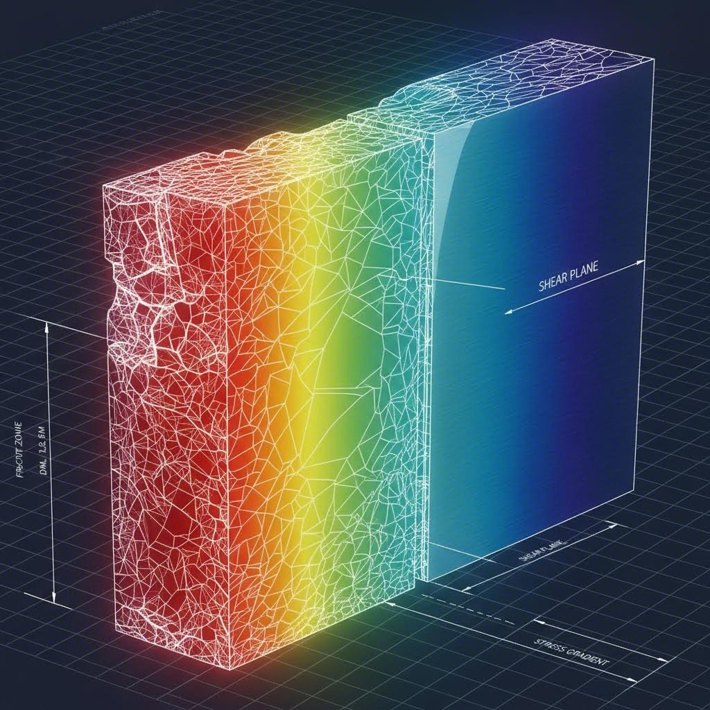

<h2>TL;DR</h2><p>Eliminating edge cracking in stamped parts, particularly in Advanced High-Strength Steels (AHSS), requires shifting focus from global ductility (necking) to local formability (fracture). Traditional rules of thumb, such as 10% cutting clearance, often fail with modern materials like Dual Phase (DP) steel. To solve this, engineers must optimize cutting clearances (often increasing to 15–20% of material thickness), select materials with high Hole Expansion Ratios (HER) validated by ISO 16630, and utilize die design strategies like "metal gainers" to reduce edge strain. Addressing the shear-affected zone (SAZ) is the single most effective method for preventing edge failure.</p><h2>The Science of Edge Cracking: Global vs. Local Formability</h2><p>A common misconception in metal stamping is that high tensile elongation guarantees resistance to cracking. In reality, edge cracking is a failure of <strong>local formability</strong>, which is distinct from the <strong>global formability</strong> measured in standard tensile tests. Global formability governs failures like necking in the body of a part, where strain is distributed. Edge cracking, however, occurs at the sheared edge where the material's microstructure has been compromised by the cutting process itself.</p><p>When a punch creates a blank, it generates a "shear-affected zone" (SAZ) or work-hardened zone. In this narrow region, the material is significantly harder and more brittle than the base metal. For AHSS grades, this effect is amplified. Dual Phase (DP) steels, for instance, consist of hard martensite islands dispersed within a soft ferrite matrix. During the shearing process, the extreme hardness differential between these phases causes microscopic voids to nucleate at the ferrite-martensite interface.</p><p>As the edge is subsequently stretched—during flanging or hole expansion—these micro-voids coalesce into macroscopic cracks long before the material reaches its theoretical elongation limit. Therefore, relying on tensile yield/elongation data to predict edge behavior is a fundamental engineering error. The controlling factor is not how much the material stretches globally, but how much the damaged edge can expand before fracture propagation occurs.</p><h2>Optimizing Cutting Clearance: The 10% Rule is Dead</h2><p>For decades, the standard die clearance was 10% of stock thickness. While effective for mild steel, this ratio is often detrimental for AHSS. Tighter clearances in high-strength materials can generate "secondary shear"—a defect where the cracks initiating from the punch and die do not meet continuously. This misalignment forces the punch to shear through the remaining material, creating a jagged, heavily work-hardened edge with a secondary burnish zone that acts as a stress riser.</p><p>Recent data from industry studies, including those by <a href="https://www.metalformingmagazine.com/article/?/materials/high-strength-steel/edge-cracking-in-advanced-automotive-steels">MetalForming Magazine</a>, suggests that <strong>Engineered Clearance</strong> is the solution. For many DP and CP (Complex Phase) grades, increasing the clearance to <strong>15–20% of material thickness</strong> creates a cleaner break. A larger clearance allows the upper and lower fracture planes to merge smoothly, minimizing the depth of the shear-affected zone and reducing the hardness spike at the edge. </p><p>This counter-intuitive approach—opening the gap to improve quality—often results in a significantly higher Hole Expansion Ratio (HER). However, this must be balanced against burr height. While larger clearances may produce a taller burr, the edge itself retains more ductility. If the burr is on the compression side of the subsequent bend, the risk of cracking is often negligible compared to the benefit of a cleaner shear face.</p><h2>Material Selection: The Hole Expansion Ratio (HER)</h2><p>When sourcing material for parts with flanged holes or stretched edges, the <strong>ISO 16630 Hole Expansion Test</strong> is the gold standard for prediction, superseding traditional tensile metrics. This test expands a punched hole with a conical punch (60° apex) until a through-thickness crack appears, providing a direct measure of the edge's ductility.</p><p>Material grade selection plays a critical role here. While DP steels are popular for their strength-to-cost ratio, their microstructural heterogeneity (hard martensite vs. soft ferrite) makes them prone to edge failure. <strong>Complex Phase (CP) steels</strong> often offer superior performance for edge-sensitive parts. CP grades utilize a matrix of bainite and precipitation-strengthened ferrite, which creates a more uniform hardness distribution. This homogeneity reduces the nucleation of micro-voids during shearing, granting CP steels significantly higher HER values compared to DP steels of similar tensile strength.</p><p>Furthermore, material cleanliness is non-negotiable. As noted by experts at <a href="https://www.ulbrich.com/blog/cracking-under-pressure-how-high-quality-metal-and-metallurgical-expertise-prevent-cracking-in-stamping/">Ulbrich</a>, inclusions and impurities (such as sulfur or oxides) serve as initiation sites for cracks. Specifying high-quality, clean steel with controlled inclusion limits helps ensure that the material's theoretical HER is achievable in production.</p><h2>Die Design & Process Engineering Solutions</h2><p>Beyond metallurgy, geometry determines destiny. When a part requires a stretch flange that exceeds the material's limits, process engineers must alter the strain path. One effective technique is the use of <strong>metal gainers</strong>. By designing a surplus of material (a "gainer") into the draw die or binder, engineers can provide extra feedstock that flows into the flange during the forming operation. This converts a pure stretch condition into a draw-stretch combination, significantly lowering the localized strain at the edge.</p><p>Tool maintenance is equally critical. A chipped or dull cutting edge increases the volume of the deformed material zone, hardening the edge further. Regular sharpening schedules are mandatory for AHSS production. Additionally, using beveled punches (often with a 3–6 degree roof top shear) can reduce the shock loading and improve the quality of the sheared face.</p><p>Implementing these advanced strategies requires manufacturing partners with specialized capabilities. For example, <a href="https://www.shao-yi.com/auto-stamping-parts/">Shaoyi Metal Technology</a> leverages high-tonnage presses (up to 600 tons) and IATF 16949-certified precision to manage the demanding processing windows of modern automotive steels. Whether for rapid prototyping or mass production, utilizing a stamper that understands the nuance of AHSS behavior prevents costly tooling iterations.</p><h2>Summary of Corrective Actions</h2><p>Eliminating edge cracking is rarely achieved by a single fix; it requires a systematic adjustment of the three primary levers: Material, Clearance, and Geometry.</p><ul><li><strong>Material:</strong> Switch to grades with high ISO 16630 HER values (e.g., CP instead of DP) and strictly control impurities.</li><li><strong>Clearance:</strong> Increase die clearance to 15–20% for AHSS to ensure a clean fracture plane and minimize the shear-affected zone.</li><li><strong>Geometry:</strong> Use metal gainers to feed material into the flange and ensure punches are kept sharp to prevent excessive work hardening.</li></ul><section><h2>Frequently Asked Questions</h2><h3>1. What is the difference between global and local formability in stamping?</h3><p>Global formability refers to a material's ability to distribute strain across a large area, resisting necking (thinning) during drawing operations. It is correlated with the n-value (work hardening exponent). Local formability, by contrast, is the material's resistance to fracture at specific stress concentrations, such as sheared edges. It is correlated with the Hole Expansion Ratio (HER) and is the primary factor in preventing edge cracking.</p><h3>2. How does cutting clearance affect edge cracking in AHSS?</h3><p>Cutting clearance dictates the quality of the sheared edge. Insufficient clearance (e.g., the traditional 10%) in AHSS causes secondary shear, creating a jagged, brittle edge profile that cracks easily. Increasing clearance to 15–20% allows the fracture cracks from the punch and die to meet cleanly, resulting in a smoother edge with less work hardening and higher ductility.</p><h3>3. What is the ISO 16630 Hole Expansion Test?</h3><p>ISO 16630 is the standard test method for evaluating the edge ductility of metallic sheets. A 10mm hole is punched into a sample (typically with 12% clearance), and a conical punch expands the hole until a through-thickness crack appears. The percentage increase in hole diameter (HER) provides a quantitative metric for the material's ability to resist edge cracking.</p><h3>4. Why does Dual Phase (DP) steel suffer from edge cracking?</h3><p>DP steel has a microstructure composed of hard martensite islands in a soft ferrite matrix. During shearing, the hardness difference between these phases creates severe stress concentrations, leading to the formation of micro-voids at the phase boundaries. These voids weaken the edge, making it highly susceptible to cracking during subsequent forming operations.</p><h3>5. What are metal gainers in die design?</h3><p>Metal gainers are geometric features added to the addendum or binder area of a die design. They provide excess material length in specific areas. During the forming or flanging process, this extra material flows into the part, reducing the amount of stretch required at the edge. This lowers the localized strain and prevents the edge from reaching its fracture limit.</p></section>