 Small batches, high standards. Our rapid prototyping service makes validation faster and easier —

Essential Methods for Automotive Die Wear Analysis

TL;DR
Automotive die wear analysis is a critical engineering discipline focused on the systematic study, prediction, and mitigation of material degradation on tooling surfaces used in high-pressure forming processes like stamping and forging. This analysis involves examining fundamental wear mechanisms, such as abrasion and adhesion, and employing advanced computational tools, including the Archard wear model combined with Finite Element Analysis (FEA). The primary objective is to optimize die materials, surface treatments, and operational parameters to extend tool life, reduce manufacturing costs, and ensure part quality.
Understanding Die Wear: Mechanisms and Classifications
Die wear is defined as the progressive loss of material from the tooling surface resulting from the friction and high contact pressure generated during interaction with sheet metal. This degradation is a primary factor limiting the lifespan of tooling in automotive manufacturing. Damage to the die surface can not only lead to the gradual erosion of the tool itself but also cause scoring or burnishing on the formed part, creating stress risers that may lead to premature component failure. Understanding the specific mechanisms of wear is the foundational step in developing effective mitigation strategies.
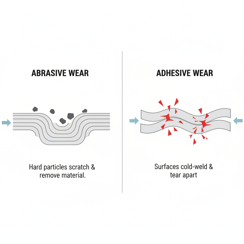
Die wear is broadly classified into two main categories: normal wear and abnormal wear. Normal wear is the expected, gradual degradation of the die surface over its operational life, resulting from controlled friction and contact. Abnormal wear, however, is often catastrophic and results from issues such as improper material selection, design flaws, metal fatigue, or corrosion. According to an analysis by measurement solutions provider Keyence, the most frequent types of abnormal wear are abrasive and adhesive wear, which together constitute a failure mode known as galling. Abrasive wear occurs when hard particles or surface asperities on the sheet metal plow into the die surface, while adhesive wear involves the micro-welding and subsequent tearing of material between the two contacting surfaces.
Other forms of abnormal wear include fatigue wear, which arises from repeated stress cycles causing microcracks that propagate and lead to flaking or peeling of the tool surface. Fretting wear is caused by minute, repetitive movements between fitted parts, leading to surface pitting and a reduction in fatigue strength. Corrosion wear occurs when chemical reactions, often accelerated by friction, degrade the die surface. The AHSS Guidelines note that factors such as the strength of the sheet metal, contact pressure, sliding velocity, temperature, and lubrication all significantly impact the rate and type of wear experienced by the tooling. Accurately identifying the dominant wear mechanism is crucial for prescribing the correct countermeasures.
To provide a clearer distinction, the characteristics of normal and abnormal wear can be contrasted:
| Aspect | Normal Wear | Abnormal Wear (e.g., Galling, Severe Abrasion) |
|---|---|---|
| Cause | Gradual material loss from controlled friction and contact under expected operating conditions. | Inappropriate die material, high contact pressure, poor lubrication, metal fatigue, corrosion, or contamination. |
| Appearance | Uniform, smooth polishing or slight erosion of the die surface over time. | Deep scratches (ploughing), material transfer (adhesion), surface cracking, flaking, or catastrophic failure. |
| Progression | Slow, predictable, and manageable through routine maintenance. | Rapid, often unpredictable, and can lead to sudden tool failure and production stoppage. |
| Mitigation Strategy | Scheduled maintenance, monitoring, and eventual replacement at the end of the planned service life. | Requires root cause analysis, material upgrades, surface treatments, process parameter optimization, and improved lubrication. |
Predictive Modeling of Die Wear: The Archard Model and FEA
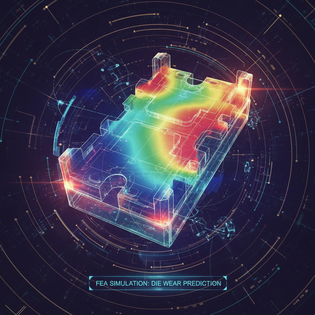
To proactively manage tool degradation, engineers increasingly rely on predictive modeling to forecast die life and identify potential failure points before they occur in production. This computational approach allows for the simulation of complex interactions between the die and workpiece, offering significant advantages in cost and time over purely experimental methods. At the forefront of this methodology is the integration of established wear theories, such as the Archard wear model, with powerful Finite Element Analysis (FEA) software.
The Archard wear model is a fundamental equation used to describe sliding wear. It posits that the volume of material lost is proportional to the normal load, the sliding distance, and a material-specific wear coefficient, while being inversely proportional to the hardness of the wearing material. While a simplification of real-world phenomena, this model provides a robust framework for estimating wear when integrated into a larger simulation environment. FEA software is used to calculate the critical parameters required by the Archard model, such as contact pressure and sliding speed, at every point on the die surface throughout the forming process.
This combination of FEA and the Archard model has been successfully applied in various automotive contexts. For example, research has demonstrated its effectiveness in predicting the failure of hammer dies during radial forging and in analyzing wear on hot stamping dies for automobile panels. By simulating the stamping or forging operation, engineers can generate wear maps that visualize high-risk areas on the die surface. These insights enable design modifications, such as adjusting radii or optimizing contact angles, to be made virtually, thereby reducing the need for expensive and time-consuming physical prototypes.
The practical application of this predictive technique generally follows a structured process. Engineers can leverage this methodology to optimize tool design and process parameters for enhanced longevity. The typical steps involved are as follows:
- Material Characterization: Obtain accurate mechanical properties for both the die steel and the sheet metal, including hardness and the experimentally determined Archard wear coefficient.
- FEA Model Development: Create a high-fidelity 3D model of the die, punch, and blank. Define the contact interfaces, friction conditions, and material behaviors within the FEA software.
- Simulation Execution: Run the forming simulation to compute the evolution of contact pressure, sliding velocity, and temperature at each node on the tool surface over the duration of the process.
- Wear Calculation: Implement the Archard wear model as a subroutine or post-processing step, using the outputs from the FEA simulation to calculate the incremental wear depth at each node for each time step.
- Analysis and Optimization: Visualize the cumulative wear distribution on the die surface. Identify critical wear zones and iteratively modify the tool geometry, material, or process parameters in the simulation to minimize the predicted wear.
Experimental Analysis and Measurement Techniques
While predictive modeling provides invaluable foresight, experimental analysis remains essential for validating simulation results and understanding the nuanced effects of material and process variables. Experimental die wear analysis involves the physical testing and measurement of wear under controlled, and often accelerated, conditions. These tests provide the empirical data needed to refine wear models, compare the performance of different tool materials and coatings, and diagnose production issues.
A common methodology is the Design of Experiments (DOE) approach, where key variables such as contact pressure, sliding speed, and lubrication are systematically varied to quantify their impact on wear volume. Specialized equipment, such as a strip-on-cylinder or pin-on-disk wear test apparatus, is often employed to replicate the sliding contact conditions found in stamping operations. For instance, a literature study on die wear testing technologies highlights the development of accelerated sliding wear tests that assess tool wear over a continuously renewed sheet metal surface, more closely mimicking actual production scenarios. The results from these tests are crucial for selecting the most robust die systems for forming advanced high-strength steels (AHSS).
Accurate measurement of the resulting wear is a critical component of this analysis. Traditional methods using profile measurement systems or coordinate measuring machines can be time-consuming and prone to operator error. Modern solutions, such as 3D optical profilometers, offer a significant advancement. These non-contact systems can capture the complete 3D topography of the die surface in seconds, allowing for precise and repeatable quantification of wear volume and depth. This enables rapid comparison between different test conditions and provides detailed data for validating FEA models. Companies like Keyence specialize in such advanced metrology, providing tools that solve common problems in accurately assessing die wear.
Based on insights from various experimental studies, several best practices can be established for conducting effective die wear tests. Adhering to these principles ensures that the data generated is reliable and relevant to real-world applications.
- Ensure the test apparatus accurately represents the contact and sliding conditions of the specific stamping or forging operation being studied.
- Precisely control and monitor key variables, including applied load (contact pressure), sliding velocity, temperature, and lubricant application.
- Use high-resolution measurement techniques to accurately quantify material loss and characterize the surface topography before and after testing.
- Select tool and sheet materials that are identical to those used in production to ensure the relevance of the test results.
- Conduct a sufficient number of repeated tests to establish statistical confidence in the findings and account for material variability.
Material Science and Process Optimization for Wear Reduction
Ultimately, the goal of automotive die wear analysis is not merely to study failure but to prevent it. This is achieved through a holistic approach that combines intelligent material selection, advanced surface engineering, and process optimization. The choice of tool material is a primary determinant of die life. Materials must balance high hardness for wear resistance with sufficient toughness to prevent chipping and cracking under extreme loads. Common choices include high-carbon, high-chromium tool steels like D2 (e.g., Cr12MoV), which offer excellent wear resistance, while specialized powder metallurgy (PM) tool steels provide a more uniform microstructure for superior toughness and fatigue life in demanding AHSS applications.
Surface hardening treatments and coatings provide another layer of defense against wear. As detailed in the AHSS Guidelines, techniques like ion nitriding create a hard, wear-resistant case on the tool surface. This is often followed by the application of a low-friction coating via Physical Vapor Deposition (PVD), such as Titanium Aluminum Nitride (TiAlN) or Chromium Nitride (CrN). These coatings not only increase surface hardness but also reduce the coefficient of friction, which is critical for minimizing adhesive wear and galling, particularly when forming coated steels. The combination of a hardened substrate and a functional coating creates a robust system capable of withstanding the high stresses of modern automotive manufacturing.
Leading suppliers in the industry integrate these principles directly into their manufacturing processes. For instance, specialists like Shaoyi (Ningbo) Metal Technology Co., Ltd. focus on producing custom automotive stamping dies by leveraging advanced CAE simulations to optimize tool design and material selection from the outset. By combining IATF 16949-certified processes with deep expertise in material science, such firms deliver tooling solutions engineered for maximum longevity and performance, helping OEMs and Tier 1 suppliers reduce lead times and improve part quality.
Process optimization is the final piece of the puzzle. This involves adjusting operational parameters to minimize stress on the tooling. For engineers tasked with designing a forming process, a systematic approach is essential. The following checklist outlines key considerations for designing a process that minimizes die wear:
- Material Selection: Choose a tool steel with the optimal balance of hardness and toughness for the specific application (e.g., forming vs. cutting) and sheet material (e.g., AHSS).
- Surface Treatment and Coating: Specify an appropriate surface hardening process (e.g., ion nitriding) followed by a low-friction PVD coating, especially for high-strength or coated sheet steels.
- Lubrication Strategy: Ensure consistent and adequate application of a suitable lubricant to reduce friction and heat at the tool-workpiece interface.
- Die Geometry: Optimize draw radii, bead profiles, and clearance to ensure smooth material flow and avoid stress concentrations that can accelerate wear.
- Operational Parameters: Control press speed and blankholder force to prevent excessive wrinkling and reduce impact loads on the tooling.
A Strategic Approach to Managing Die Longevity
The analysis of automotive die wear has evolved from a reactive, failure-driven exercise into a proactive, data-centric engineering discipline. By integrating a deep understanding of fundamental wear mechanisms with the predictive power of computational modeling and the empirical validation of experimental testing, manufacturers can significantly extend the operational life of their tooling. This strategic approach is not merely about preventing catastrophic failures; it is about optimizing the entire manufacturing system for efficiency, consistency, and cost-effectiveness.
The key takeaway is that managing die wear is a multifaceted challenge that requires a synergistic application of material science, simulation technology, and process control. The selection of advanced tool steels and surface coatings, guided by predictive FEA simulations using models like Archard's theory, allows for the design of more resilient and durable dies. Simultaneously, rigorous experimental analysis provides the crucial real-world data needed to validate these models and refine process parameters. Ultimately, a comprehensive automotive die wear analysis program empowers engineers to make informed decisions that reduce downtime, improve part quality, and maintain a competitive edge in a demanding industry.