 Small batches, high standards. Our rapid prototyping service makes validation faster and easier —

Mastering Automotive Forging Die Design: Key Principles
TL;DR
Automotive forging die design is the highly specialized engineering process of creating robust, precise tooling used to shape metal into high-strength automotive components. The primary goals are to ensure the final part meets strict standards for durability, dimensional accuracy, and cost-effective manufacturability. This involves balancing material properties, part geometry, and the forging process itself to produce reliable parts like crankshafts, gears, and suspension components.
Fundamental Principles of Forging and Die Design
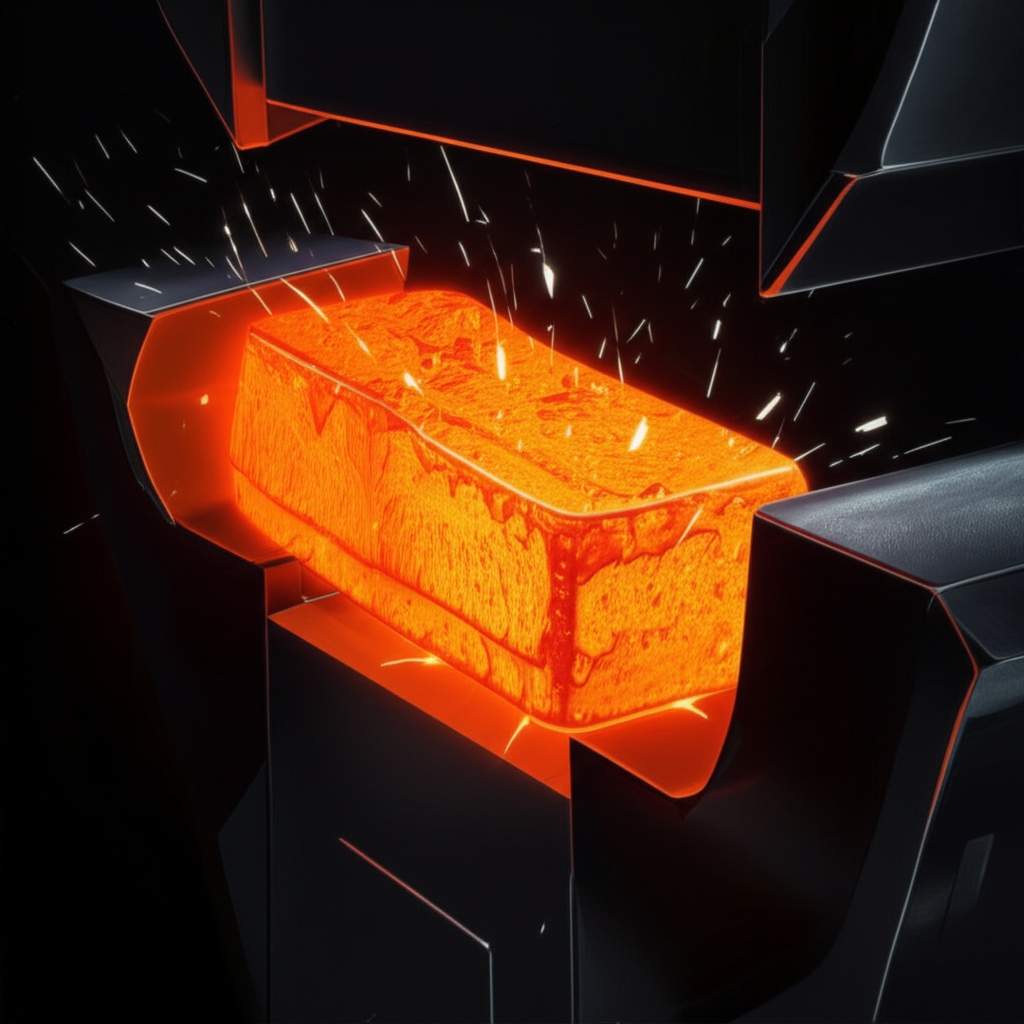
At its core, forging is a manufacturing process that shapes metal using localized compressive forces. Unlike casting, which involves molten metal, forging refines the metal's grain structure, aligning it with the part's shape. This grain flow enhances the component's mechanical properties, resulting in superior strength, toughness, and fatigue resistance, which are critical for automotive applications. The die is the central tool in this process; it is a specialized mold, typically made of high-strength tool steel, that dictates the final shape of the workpiece.
The two primary methods of forging are open-die and closed-die. Understanding their differences is fundamental to die design:
- Open-Die Forging: In this method, the workpiece is not completely confined by the dies. It is hammered or pressed between flat or simple contoured dies, allowing the metal to flow outward. This process is highly flexible and suitable for large, relatively simple parts like shafts or blocks, but it offers less dimensional precision.
- Closed-Die Forging (Impression Die Forging): This is the predominant method for automotive components. The workpiece is placed in a die that contains a precise impression of the desired shape. As the dies close, the metal is forced to fill the cavity, creating a dimensionally accurate, near-net-shape part. As detailed in a guide by HARSLE, this method is ideal for complex geometries and high-volume production, ensuring consistency and minimizing subsequent machining.
The quality of the die design directly influences the final product's integrity. A well-designed die ensures uniform material flow, prevents defects like laps or cracks, and maximizes the tool's lifespan. The design process must account for the material's behavior under immense heat and pressure to create a component that is both strong and precisely formed.
Key Design Considerations for Automotive Forging Dies
Effective automotive forging die design is a meticulous process that balances multiple technical factors to ensure manufacturability and part performance. Each consideration directly impacts the final component's quality, cost, and durability. For engineers and designers, mastering these elements is essential for success.
Parting Line Placement
The parting line is the surface where the two halves of the die meet. Its placement is one of the most critical decisions in die design. An optimal parting line simplifies metal flow, minimizes flash (excess material), and facilitates the removal of the forged part. A poorly chosen line can trap material, create defects, and increase the need for secondary machining. The goal is to locate it at the largest cross-section of the part, creating a natural and balanced division.
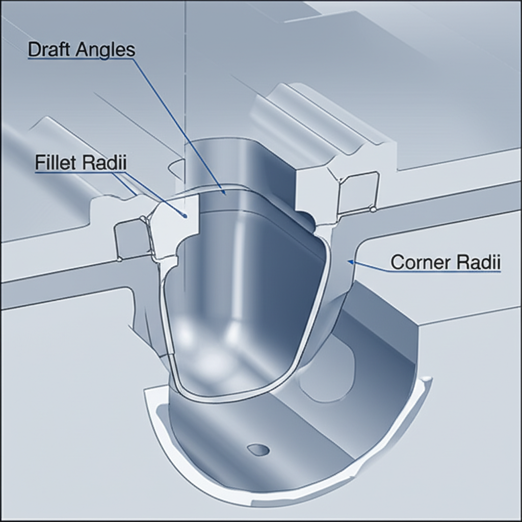
Draft Angles
Draft angles are slight tapers applied to the vertical surfaces of the die cavity. As explained in an article by Frigate.ai, their primary purpose is to allow for easy removal of the part from the die after forging. Without adequate draft, the component can stick, leading to damage to both the part and the die. Typical draft angles range from 3 to 7 degrees, depending on the complexity of the shape and the material's properties. Insufficient draft can cause production delays and increase tool wear.
Corner and Fillet Radii
Sharp internal and external corners are detrimental in forging. Sharp internal corners impede metal flow and create stress concentrations, which can lead to cracks or fatigue failure in the final part. Fillet radii (rounded internal corners) and corner radii (rounded external corners) are used to promote smooth material flow into all parts of the die cavity. Generous radii also increase the lifespan of the die by reducing wear and the risk of cracking under cyclic thermal and mechanical stress.
Ribs and Webs
Ribs are thin, protruding features, while webs are the thin sections of metal connecting them. Designing these features requires careful attention to their dimensions. Ribs that are too tall and thin can be difficult to fill with material, leading to underfill defects. Webs that are too thin can cool too quickly, potentially causing cracks or warping. A key design principle is to maintain a proper height-to-width ratio for ribs and ensure adequate thickness for webs to facilitate complete material fill and structural integrity. For those seeking specialized forging solutions, companies like Shaoyi Metal Technology offer custom services with in-house die manufacturing, which can be invaluable for optimizing complex designs for production.
Materials Selection for Forging Dies
The material chosen for a forging die is critical to its performance, longevity, and the overall cost-effectiveness of the manufacturing process. Dies are subjected to extreme conditions, including high temperatures, immense pressures, and abrasive wear. Therefore, the selected material must possess a specific combination of properties to withstand this harsh environment. The primary criteria for die material selection include high-temperature strength (hot hardness), thermal shock resistance, toughness to resist cracking, and excellent wear resistance.
Tool steels are the most common choice for hot forging dies due to their balanced properties. Several grades are widely used, each suited for different applications:
- H13 Tool Steel: This is one of the most popular materials for hot forging dies. H13 is a chromium-molybdenum-vanadium hot-work tool steel that offers an excellent combination of high-temperature strength, toughness, and good resistance to thermal fatigue. Its versatility makes it suitable for a wide range of automotive forging applications.
- High-Speed Steels (e.g., M2, M42): These steels are used when exceptional wear resistance and the ability to maintain hardness at very high operating temperatures are required. They are often chosen for dies used in high-volume production where tool life is a primary concern.
- Powder Metallurgy (PM) Steels: PM steels offer superior wear resistance and toughness compared to conventional tool steels. Their uniform microstructure provides enhanced durability and resistance to chipping, making them ideal for forging complex parts or difficult-to-form alloys.
The selection process involves a trade-off between performance and cost. While advanced materials like PM steels or carbide inserts offer the longest die life, they come at a higher initial cost. Therefore, the choice depends on factors such as the production volume, the complexity of the part, and the material being forged. Proper material selection, combined with appropriate heat treatment and surface coatings, is essential for maximizing die life and ensuring consistent part quality.
Integrating DFM (Design for Manufacturability) Principles
Design for Manufacturability (DFM) is a proactive engineering practice focused on designing parts in a way that makes them easier and more cost-effective to produce. In the context of automotive forging, DFM principles are crucial for bridging the gap between a theoretical design and a practical, high-quality component. By considering the limitations and capabilities of the forging process early in the design phase, engineers can prevent costly revisions, reduce material waste, and improve the overall efficiency of production.
One of the core tenets of DFM in forging is design simplification. As highlighted in an article by Jiga.io, complex geometries with deep pockets, non-symmetrical features, or drastic changes in thickness can complicate material flow and increase tooling complexity. This not only raises the cost of the dies but also increases the likelihood of manufacturing defects. By simplifying the part geometry—such as standardizing radii, minimizing deep sections, and aiming for symmetry where possible—designers can facilitate a smoother, more predictable forging process.
Another key DFM practice is to design for a near-net shape. The goal is to forge a part that is as close as possible to its final dimensions, thereby minimizing the need for secondary machining. This reduces material waste, cuts down on processing time, and lowers the overall cost per part. Achieving a near-net shape requires careful planning of the initial billet size and shape, as well as optimizing the die design to ensure complete and accurate material fill. Ultimately, integrating DFM principles transforms the design process from a siloed activity into a holistic approach that accounts for the entire manufacturing lifecycle, leading to more robust and economical automotive components.
The Role of Simulation and Technology (CAD/CAM/FEA)
Modern automotive forging die design has been revolutionized by advanced technologies that enable engineers to plan, visualize, and validate their designs with unprecedented precision. The integration of Computer-Aided Design (CAD), Computer-Aided Manufacturing (CAM), and Finite Element Analysis (FEA) has shifted the process from one of trial-and-error to a science-driven methodology. These tools work in concert to optimize die performance, predict manufacturing issues, and ensure the final product meets specifications before any physical tooling is created.
The process begins with CAD software, which is used to create detailed 3D models of both the final forged part and the dies themselves. This digital environment allows designers to meticulously craft every aspect of the die, from the parting line and draft angles to the complex cavity geometry. Once the design is modeled, it serves as the foundation for the next stages of the digital workflow.
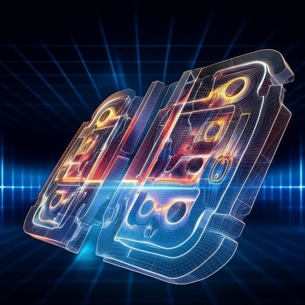
Next, FEA simulation software is used to analyze the forging process virtually. As discussed by Cast & Alloys, this technology is a game-changer. FEA can predict how the metal will flow within the die cavity, identify potential defects like underfills or folds, analyze temperature distribution, and calculate the stresses on the die. By running these simulations, engineers can identify and correct design flaws early, optimizing material flow and ensuring the part will be forged correctly. This dramatically reduces the need for expensive and time-consuming physical prototypes.
Finally, CAM software translates the validated CAD model into instructions for CNC (Computer Numerical Control) machines, which then machine the physical die blocks from hardened tool steel. CAM ensures that the intricate details of the digital design are transferred to the physical tool with extreme accuracy. This synergy of CAD, FEA, and CAM technologies enables the creation of highly optimized, durable, and precise forging dies, leading to higher quality automotive components and a more efficient manufacturing process.