 Small batches, high standards. Our rapid prototyping service makes validation faster and easier —
  EN
EN


Single-Operation Die Stamping for Automotive Parts: Selection, Sizing, and When to Upgrade
A single-operation die does one job per press stroke — blank, pierce, bend, or draw — and nothing more. Four signals tell you it's the right tool for a part: the part is wider than standard coil stock, annual volume sits below roughly 20,000 pieces, material runs thicker than 6mm, or the part is still in prototype validation. Miss any of those signals and you're either overpaying for tooling you don't need or underbuilding a process that can't hold up in production.
This guide covers how to size the press correctly, what actually breaks on single-die parts, and — the part almost nobody explains with real numbers — exactly when and how to move up to progressive or transfer tooling.
What a Single-Operation Die Actually Is
Calling it "the cheap option" misses the point.
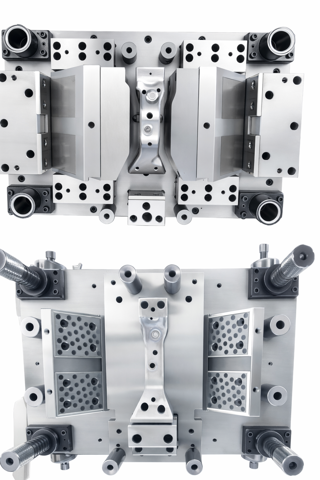
A single-operation die — sometimes called a simple die or a tryout die — performs exactly one operation per stroke: blanking, piercing, bending, drawing, or flanging. A complex part usually passes through several of these dies in sequence before it's finished, each one doing its one job and handing the part to the next station or the next setup.
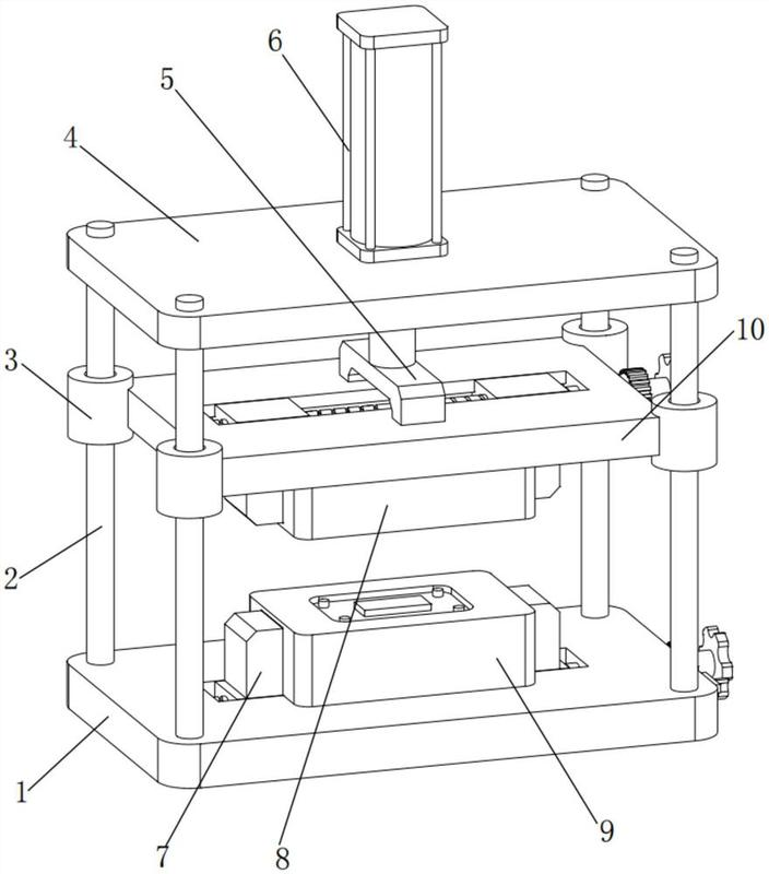
The tooling itself splits into two halves. The upper half carries the shank that connects to the press slide, the punch holder, the punch itself, and a stripper plate that peels the material off the punch on the return stroke. The lower half carries the die holder, the die block, guide posts and bushings that keep the two halves aligned to within 0.005–0.01mm, a locating pin to place the blank consistently, and an ejector to push the finished part clear.
Four Signals That Say Single Die Is the Right Call
Check your part against these before assuming you need progressive tooling — or before assuming you don't.
Part size is the first filter. Standard coil stock tops out around 600mm wide. If the part's footprint exceeds that, a progressive die simply can't feed it, regardless of volume.
Volume is the second, and the one buyers get wrong most often in both directions. Below roughly 20,000 pieces a year, a progressive die's tooling cost rarely amortizes fast enough to beat a single die's lower upfront investment.
Material thickness matters too. Past 6mm, you're into large-tonnage single-station territory — a job for a heavy single-operation die, not a multi-station progressive setup built around thinner strip.
And the fourth signal isn't about the part at all — it's about where you are in the program. Prototype and design-validation work needs tooling that can absorb a design change without a full rebuild. A single die takes that change far cheaper than a progressive die does.
Any one of these four showing up is reason enough to default to single-operation tooling first, then reconsider as the program matures. Our die design and manufacturing capability covers all three tooling types under one roof, which matters once you get to the upgrade decision later in this guide.
How to Size the Press — The Real Formula, Worked Through
The three forces that matter come from three different deformation types, and each has its own formula. The blanking force formula itself is straightforward — shear area times shear strength — but the other two operations bring their own variables into play.
Blanking force  = Perimeter (mm) × Thickness (mm) × Material shear strength (MPa)
Bending force   = (1.33 × Length × Thickness² × Tensile strength) / Die opening width
Drawing force   = π × Punch diameter × Thickness × Tensile strength × Draw ratio (0.6–0.9)
Total press tonnage = (Blanking force + Bending or Drawing force) × 1.3 safety factor
Here's what that looks like on a real part: a 300mm × 200mm × 3mm carbon steel bracket in DC01, with a blanking perimeter of roughly 1,200mm.
Blanking force ≈ 1,200mm × 3mm × 280 MPa = 1,008 kN ≈ 100 tonnes
Add the 1.3 safety factor and round up to the nearest standard press size, and this bracket goes on a 160-tonne press — not the 100-tonne press the raw number suggests, because running a press at its rated limit shortens its life and leaves no margin for material variation batch to batch. The formula changes for bending and drawing operations because the deformation mechanism is different, but the discipline is the same: calculate first, don't estimate from a similar part you built last year.
What Actually Goes Wrong With Single-Die Parts
A single-operation die is mechanically simple, which is exactly why the failure modes are well understood and mostly preventable.
| Defect | Root Cause | Fix |
|---|---|---|
| Excess burr | Clearance too large, or a dull cutting edge | Reset clearance, regrind or replace the punch/die edge |
| Torn section edge | Clearance too small | Open the clearance to 6–10% of material thickness |
| Bend springback | Material's elastic recovery after forming | Predict the angle with CAE, pre-compensate the die angle 2–5° |
| Draw cracking | Draw ratio too aggressive, or wrong blank-holder force | Optimize draw ratio to ≤2.0 via CAE, adjust holder force |
| Draw wrinkling | Insufficient blank-holder force | Increase holder force, add or reposition draw beads |
| Hole position shift | Insufficient locating precision | Upgrade to spring-loaded side-push location with a V-block guide |
None of these show up as a mystery on a properly run line. Each one traces back to a specific, measurable cause, which is why first-piece inspection — full dimensional check before the run starts, with key dimensions held within ±30% of tolerance midpoint — catches most of them before they become a batch problem. This is the same discipline behind our stamping quality control process more broadly, not something unique to single-die work.
The Upgrade Path Nobody Explains Properly
Most suppliers will tell you single die "can upgrade to progressive later." Almost none will tell you at what volume, what it costs, or what carries over. Here's the actual path, staged.
| Stage | Tooling | Volume Range | Tooling Investment | Lead Time |
|---|---|---|---|---|
| Design validation | Single die, soft tool steel | 10–100 pieces | ¥3,000–15,000 | 2–3 weeks |
| Small-batch trial | Single die, standard tool steel | 100–5,000 pieces | ¥8,000–40,000 | 3–4 weeks |
| Medium-batch transition | Multiple single dies + semi-auto feed | 5,000–30,000 pieces | ¥20,000–80,000 | 4–6 weeks |
| Mass production | Progressive or transfer die | >50,000 pieces/year | ¥50,000–300,000 | 5–8 weeks |
The part that actually matters isn't the table — it's what moves between stages. Every parameter captured during the single-die runs — measured springback, actual material thinning, the clearance that worked in trial — carries directly into the progressive or transfer die design that follows. That's what cuts the mass-production tooling's commissioning cycle by more than half compared to starting the progressive die design cold. Skip a stage and you lose that carryover. A part that jumps straight from a sketch to a progressive die usually needs more rework rounds, not fewer, because nobody validated the forming behavior on cheap tooling first.
Read our progressive die guide for what that stage actually involves once you're past this threshold.
Not every high-volume part fits the progressive mold, though. A part with deep draws, independent forming stations, or geometry that a continuous strip can't carry through a die set often makes more sense on transfer tooling, even at the same volume that would otherwise call for a progressive die. Design flexibility matters here as much as raw speed does — a transfer press moves the part between independent stations rather than threading it through a single continuous strip, which is exactly what deep-draw geometry needs room for.
This distinction trips up more buyers than the single-die-versus-progressive-die question does, mostly because both options look similar on a quote sheet until the tooling is already cut and the geometry problem shows up on the shop floor instead, well after the tooling budget is already spent. Our transfer die process breakdown covers when that fits better than a progressive setup, and it's worth reading before you commit tooling budget to either path.
When Single Die Isn't Enough
A single die has real ceilings, and pretending otherwise just delays the problem to a worse moment.
Process capability is the first ceiling. Positioning-dependent dimensions on single-die parts typically run a CPK of 0.8–1.2, and even non-positioning dimensions top out around 1.0–1.33. Automotive safety-critical parts routinely require CPK ≥1.33 under the harmonized AIAG-VDA capability thresholds, which single-operation tooling structurally cannot guarantee run after run.
Volume is the second. Once annual demand stabilizes above roughly 50,000 pieces, both unit cost and achievable throughput flip in favor of progressive tooling — the math in the table above stops favoring single die past that point, not before it.
And if the end goal is a fully unattended production line, a single die's manual blank placement is the bottleneck no amount of process discipline fixes. That's a feed-system and tooling-architecture problem, not an operator-training problem.
What To Do Next
Pull four numbers before you spec tooling for a new part: part footprint, annual volume, material thickness, and program stage. If any one of them points to single die, don't over-tool the first run just because the part will eventually go to mass production — the upgrade path exists precisely so you don't have to guess right on day one.
If you're not sure which stage your part is actually at, send your drawing for a tooling strategy review — you'll get a straight read on whether single die, and which upgrade stage, actually fits your volume.
FAQ
Five questions come up more than any other once a buyer has settled on single-operation tooling.
Can a single-operation die meet automotive-grade quality requirements?
It can meet basic functional and dimensional requirements, but CPK typically runs 0.8–1.2, below the ≥1.33 progressive dies achieve. It's well suited to R&D and small-batch stages; for mass production, plan to evaluate an upgrade.
How long does a single-operation die actually last?
Standard tool steel (DC53) holds a punch and die edge life of 300,000–600,000 strokes, with total die life exceeding a million. Powder high-speed steel (ASP23) with a TiCN coating extends that edge life to 1–2 million strokes.
Does upgrading to a progressive die mean starting the design over?
No. Springback, material thinning, and clearance data captured during single-die trial runs carry directly into the progressive die design, typically cutting mass-production tooling commissioning time by more than half.
Can single-die production run semi-automated or fully automated?
Yes, in three steps: add a roller feeder for semi-automated feeding (25–40 strokes/minute); chain multiple single dies with robotic transfer (15–25 strokes/minute); or move to a progressive die outright (40–80+ strokes/minute). Which one fits depends on your volume target.
What design rules make a part easier to produce on a single-operation die?
A few that matter most: minimum punched hole diameter ≥1.0× material thickness for steel (0.8× for aluminum); minimum hole-to-edge distance ≥1.5× thickness; minimum bend inner radius ≥1.0× thickness for steel (0.5× for aluminum). Designing to these up front measurably cuts tryout rework.
Written by: Xu Xungui, Stamping & Die Process Engineer — background in stamping forming process, die structural design, sheet metal forming simulation, and part quality control across full-vehicle stamped component programs, with particular focus on resolving springback, wrinkling, and dimensional drift issues.
Reviewed by: Nansen (Sun Nan), International Business Manager
Last updated: 2026-08-04