 Small batches, high standards. Our rapid prototyping service makes validation faster and easier —

Preventing Tearing in Deep Draw Stamping: Diagnostic Guide
TL;DR
Preventing tearing in deep draw stamping requires a precise balance between material flow and stretch. Tearing typically occurs when radial tensile stresses in the cup wall exceed the material's ultimate tensile strength, often caused by excessive flow resistance. To eliminate this defect, engineers must optimize three critical variables: maintain a Limiting Draw Ratio (LDR) below 2.0, calibrate the Blank Holder Force (BHF) to prevent wrinkling without locking the metal, and ensure die entry radii are sufficiently large (typically 4–8 times material thickness) to reduce friction. Success relies on viewing the process as a system where lubrication, tool geometry, and material properties (n-value/r-value) work in unison.
The Physics of Tearing: Stress, Strain, and Material Flow
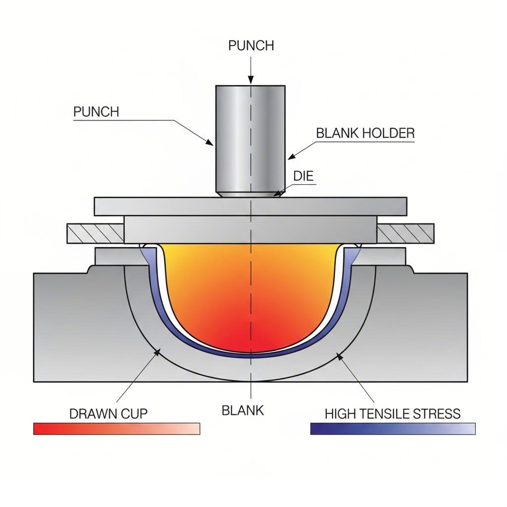
Deep drawing is a battle between two opposing forces: radial tensile stress and circumferential compressive stress. Understanding this physics is the first step to preventing tearing in deep draw stamping. As the punch strikes the blank, it pulls the metal into the die cavity. The material in the flange area creates resistance because it must compress circumferentially to fit into the smaller diameter of the die. If this resistance to flow becomes too high, the punch continues to travel, stretching the cup wall until it thins and eventually fractures.
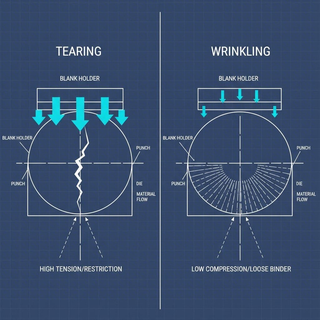
This failure mode is distinct from wrinkling. Wrinkling occurs when the metal flows too freely (low compressive stress), causing it to buckle. Tearing, conversely, happens when the metal cannot flow freely enough. The material hits its tensile limit before it can be drawn into the die. According to The Fabricator, successful operations manage this by controlling the "speed" of the material entering the die. Draw beads and binder pressure act like brakes; applying too much braking force causes the material to snap rather than flow.
Designers must also identify the location of the tear to diagnose the root cause. A fracture at the bottom cup radius (where the punch nose contacts the metal) usually indicates excessive punch force relative to the wall strength. A vertical split in the sidewall, however, often suggests that the material has exhausted its work-hardening capacity or that the LDR is too aggressive for a single station.
Critical Design Parameters: Radii, Clearance, and LDR
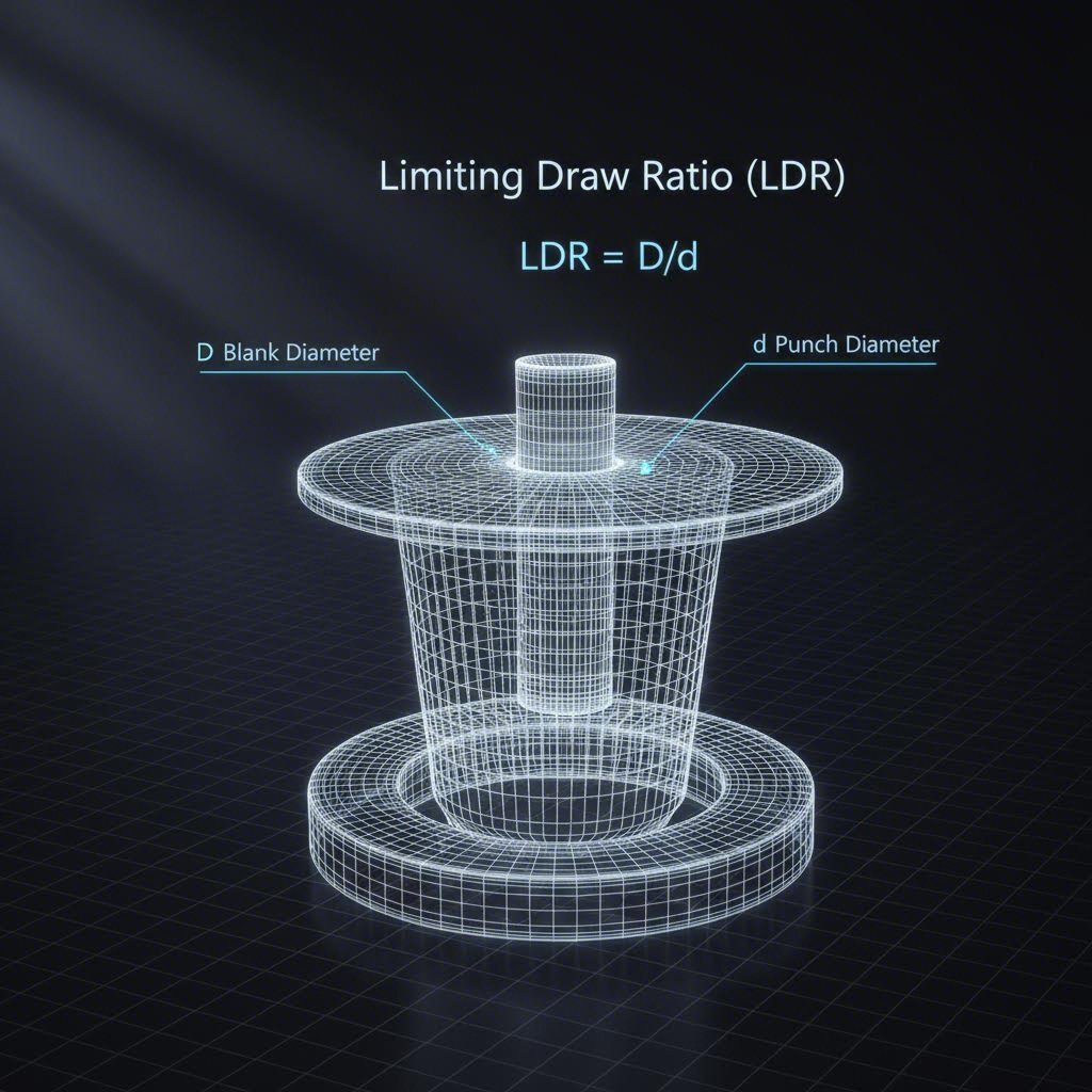
Geometry dictates the limits of metal forming. The most common culprit for tearing is an aggressive Limiting Draw Ratio (LDR). The LDR is defined as the ratio of the blank diameter ($D$) to the punch diameter ($d$).
- The Formula: $LDR = D / d$
- The Rule: For most cylindrical draws in steel, an LDR $\le 2.0$ is the safe upper limit for a first draw. This equates to a reduction of roughly 50%.
If your calculation exceeds 2.0, the material will likely tear because the force required to draw the large flange exceeds the strength of the cup wall. In these cases, a multi-stage draw (redrawing) is required. Macrodyne advises stepping down reductions: 50% for the first draw, 30% for the second, and 20% for the third.
Die Entry and Punch Radii
The radius over which the metal flows acts as a fulcrum. A die entry radius that is too small creates a sharp corner that restricts flow and concentrates stress, leading inevitably to fracture. A general rule of thumb is that the die radius should be 4 to 8 times the material thickness. Conversely, a punch nose radius that is too sharp can cut into the material like a knife. Polishing these radii is non-negotiable; even minor tool marks can increase friction enough to cause tearing.
Die Clearance
Clearance is the gap between the punch and the die. Unlike cutting operations where tight clearance is desired, deep drawing requires space for the metal to flow. Ideally, the clearance should be 107% to 115% of the material thickness. If the clearance is exactly the material thickness or less, the tool acts as an ironing die, thinning the wall and drastically increasing the risk of tearing at the top of the stroke.
Process Control: Blank Holder Force & Lubrication
Once tooling is built, the Blank Holder Force (BHF) becomes the primary variable for the press operator. The blank holder (or binder) acts as a regulator. Its job is to apply just enough pressure to suppress wrinkles, but not so much that it pins the flange and prevents inward flow.
There is a narrow "process window" for BHF:
- Too Low: Wrinkles form in the flange. These wrinkles then get pulled into the die gap, acting like a wedge that jams the part and causes a tear.
- Too High: The friction prevents the flange from moving. The punch pushes through the bottom of the cup, tearing the metal (a "bottom out" failure).
Industry data suggests BHF is typically 30% to 40% of the maximum punch force. Die-Matic recommends using standoffs set to approximately 110% of material thickness to prevent excessive pinching. For complex geometries, hydraulic cushions or servo presses offer variable BHF profiles that can change pressure during the stroke, optimizing flow at critical moments.
Lubrication is equally vital. High-pressure lubricants separate the tool from the workpiece, reducing the coefficient of friction. In deep drawing, different zones may require different lubrication strategies: the flange needs lubrication to slide, but the punch nose often benefits from less lubrication (high friction) to grip the material and prevent thinning at the bottom radius.
Achieving this level of process control—from BHF adjustments to precision die maintenance—often requires specialized partners. For manufacturers scaling from prototype to mass production, companies like Shaoyi Metal Technology offer comprehensive stamping solutions, leveraging IATF 16949-certified precision and press capabilities up to 600 tons to bridge the gap between engineering theory and production reality.
Material Selection: The Role of n-Value and r-Value
Not all metals are created equal. If tooling and process parameters are correct but tearing persists, the material grade may be the bottleneck. Two properties are paramount for deep drawing:
- n-value (Work Hardening Exponent): This measures a material's ability to distribute strain. A high n-value means the material strengthens as it stretches, forcing deformation to spread to adjacent areas rather than localizing in a neck and snapping. Stainless steels typically have high n-values, making them excellent for deep drawing despite their strength.
- r-value (Plastic Strain Ratio): This measures the material's resistance to thinning. A high r-value (anisotropy) indicates the metal prefers to flow from the width and length directions rather than thinning in the thickness direction. According to Wedge Products, selecting Deep Drawing Quality (DDQ) or Interstitial-Free (IF) steels with high r-values can eliminate tearing issues that standard commercial grades cannot handle.
Troubleshooting Checklist: A Systematic Approach
When tearing stops the line, use this diagnostic workflow to identify the root cause systematically. Avoid changing multiple variables at once.
| Step | Variable to Check | Diagnostic Question | Corrective Action |
|---|---|---|---|
| 1 | LDR / Reduction | Is the reduction > 50%? | Add a redraw station or anneal the part. |
| 2 | Lubrication | Is the part dry or hot? | Apply high-pressure lubricant; check for coverage. |
| 3 | Blank Holder Force | Is the flange shiny/burnished? | Reduce BHF incrementally until wrinkling starts, then back off slightly. |
| 4 | Clearance | Is the top edge ironed/bright? | Verify clearance is 110%+ of material thickness. |
| 5 | Radii | Are radii rough or sharp? | Polish die entry; increase radius to 4-8x material thickness. |
| 6 | Material | Is the coil within spec? | Check certs for n-value/r-value; inspect for variations in thickness. |
For further diagnostics on specific defects, Accurate Forming outlines how issues like burrs on the blank edge or misalignment can mimic tearing problems by restricting flow flow improperly.
Mastering the Draw
Preventing tearing in deep draw stamping is rarely about fixing a single variable; it is about balancing the entire tribological system. By adhering to the physics of metal flow, maintaining the Limiting Draw Ratio, and rigorously controlling Blank Holder Force, manufacturers can achieve consistent, defect-free parts. Whether you are adjusting an existing die or designing a new progression, the focus must always remain on facilitating flow while managing stretch.
Frequently Asked Questions
1. What is the difference between tearing and wrinkling in deep drawing?
Tearing and wrinkling are opposite failure modes. Wrinkling occurs when compressive stresses in the flange cause the material to buckle, typically due to insufficient Blank Holder Force (BHF). Tearing occurs when tensile stresses in the wall exceed the material's strength, often caused by excessive BHF, tight radii, or poor lubrication that restricts material flow.
2. How do I calculate the Limiting Draw Ratio (LDR)?
The Limiting Draw Ratio is calculated as the diameter of the blank divided by the diameter of the punch ($LDR = D / d$). For most materials, a safe LDR for a single draw is 2.0 or less, meaning the blank diameter should be no more than double the punch diameter.
3. Can changing the lubricant prevent tearing?
Yes, lubrication is critical. If friction is too high at the die entry or under the blank holder, the material cannot flow into the die, leading to tearing. Switching to a high-pressure, heavy-duty lubricant designed for deep drawing can reduce friction and allow the metal to flow freely, preventing fractures.