 Small batches, high standards. Our rapid prototyping service makes validation faster and easier —

Optimizing Gate Location in Die Casting: Essential Strategies

TL;DR
Optimizing gate location in die casting is a critical engineering decision that involves placing the molten metal entry point strategically to ensure flawless part formation. The fundamental principle is to position the gate at the thickest section of the casting. This approach promotes complete, uniform filling, achieves directional solidification from thin to thick sections, and is essential for minimizing critical quality defects such as shrinkage, porosity, and cold shuts.
The Fundamental Principles of Gate Location in Die Casting
In any die casting process, the gating system is the network of channels that guides molten metal from the injection system into the mold cavity. The gate itself is the final, crucial orifice through which the metal enters the part's impression. Its design and location are paramount to the success of the casting. A poorly placed gate can lead to a cascade of defects, resulting in scrapped parts and increased production costs. The primary objective is to control the metal flow to produce a sound, dense, and dimensionally accurate casting.
The most widely accepted foundational principle is to locate the gate at the thickest section of the component. As detailed by casting experts at CEX Casting, this strategy is designed to facilitate directional solidification. Solidification should begin in the sections farthest from the gate and progress towards it, with the thickest section (at the gate) being the last to solidify. This ensures a continuous supply of molten metal to feed the casting as it shrinks during cooling, effectively preventing shrinkage porosity, a common and serious defect where internal voids form due to insufficient metal.
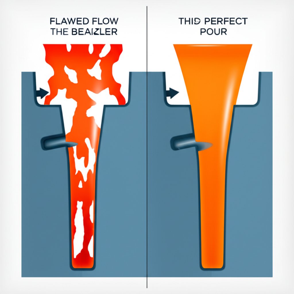
Furthermore, proper gate location ensures the mold cavity fills in a smooth, uniform manner. The goal is to achieve a laminar flow of metal, avoiding the turbulence that can trap air and oxides within the casting, leading to gas porosity and inclusions. By directing the flow from a thick section, the metal can move progressively into thinner areas, pushing air ahead of it towards vents and overflows. Incorrect placement can cause premature solidification in thin sections, blocking flow paths and resulting in incomplete filling, a defect known as a cold shut.
Critical Factors Influencing Gate Placement Strategy
While the 'thickest section' rule provides a solid starting point, optimizing gate location for modern, complex components requires a multi-faceted analysis. Engineers must balance several competing factors to achieve the desired outcome, as the ideal location is often a compromise between theoretical principles and practical constraints. Ignoring these variables can lead to suboptimal results even when following the basic rule.
The geometry of the part is the most significant factor. Symmetrical parts often benefit from a central gate to ensure the metal radiates outward evenly. However, for parts with intricate features, thin walls, and sharp corners, a single gate may be insufficient. As explained in a detailed guide by Anebon, complex geometries may necessitate multiple gates to reduce the distance the metal must travel, thereby maintaining temperature and ensuring complete filling without premature solidification. The location and design must also consider post-processing; gates should be placed where they can be easily removed without damaging the part's functional or aesthetic surfaces.
Other critical considerations that influence the final decision include:
- Material Properties: Different alloys have unique flow characteristics and solidification rates. For example, zinc alloys cool faster than aluminum alloys and may require larger gates or shorter flow paths to prevent cold shuts.
- Wall Thickness: The gate should feed from a thick to a thin section. Abrupt changes in wall thickness are challenging and require careful gate placement to avoid turbulence and ensure both sections fill properly.
- Flow Distribution: The gate must be positioned to promote a balanced filling pattern, preventing issues like 'jetting' where metal sprays directly across the cavity and erodes the mold wall. The goal is a smooth, continuous flow front.
- Venting and Overflows: Gate location must work in concert with air vents and overflow wells. The filling pattern established by the gate should effectively drive air and impurities towards these exits, ensuring they are not trapped within the final casting.
In high-performance industries like automotive, where components must withstand extreme stress, material and process selection are paramount. While die casting is excellent for complex shapes, for certain structural parts requiring maximum strength, processes like precision forging are employed. Companies such as Shaoyi (Ningbo) Metal Technology specialize in these robust automotive forging parts, where the principles of metal flow and die design are just as critical. This highlights that a deep understanding of tooling and material science is essential across advanced metal forming processes.
Advanced Methodologies: Using Simulation to Optimize Gate Location
In modern manufacturing, relying solely on empirical rules and past experience is no longer sufficient for optimizing gate location, especially for high-stakes applications. The industry has increasingly adopted advanced computational tools, such as casting simulation software, to predict and refine the die casting process before any steel is cut for the mold. This data-driven approach saves significant time and cost by minimizing trial-and-error on the foundry floor.
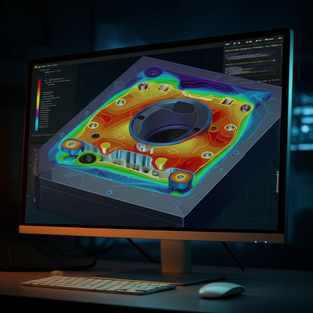
These software packages utilize methods like Finite Element Analysis (FEA) and Computational Fluid Dynamics (CFD) to create a virtual model of the die casting process. As noted in research abstracts on platforms like ScienceDirect and Springer, these computer-integrated systems allow for the accurate and fast determination of optimal gate positions. Engineers can input the part's 3D model, select the alloy, and define process parameters like injection speed and temperature. The software then simulates how the molten metal will flow, fill the cavity, and solidify.
A typical simulation-driven optimization process involves the following steps:
- Model Preparation: A 3D CAD model of the part and the initial gating system design is imported into the simulation software.
- Parameter Input: The specific alloy properties, die and metal temperatures, and injection parameters (plunger speed, pressure) are defined.
- Simulation Run: The software simulates the filling and solidification phases, calculating variables like flow velocity, temperature distribution, pressure, and areas of potential air entrapment.
- Results Analysis: Engineers analyze the simulation output to identify potential defects. This includes locating hot spots (risk of shrinkage), tracking the flow front to find potential weld lines, and identifying areas where air might be trapped (risk of porosity).
- Iteration and Refinement: Based on the analysis, the gate location, size, or shape is adjusted in the CAD model, and the simulation is run again. This iterative process is repeated until a design is achieved that minimizes predicted defects and ensures a sound casting.
This analytical approach transforms gate design from an art into a science. It enables engineers to visualize and solve problems that would be invisible until after production, making it an indispensable tool for producing high-quality, reliable die-cast components.
Gate Design for Complex and Thin-Walled Castings
While standard principles apply broadly, castings with highly complex geometries or extremely thin walls present unique challenges that demand specialized gating strategies. For these parts, such as intricate electronic enclosures or lightweight automotive components, a conventional single gate at the thickest section may fail to produce an acceptable part. The long and tortuous flow paths can cause the molten metal to lose heat rapidly, leading to premature solidification and incomplete filling.
For long, thin-walled parts, a primary strategy is the use of multiple gates. By introducing molten metal at several points along the part's length, the flow distance for any single stream is significantly reduced. This helps maintain the metal's temperature and fluidity, ensuring the entire cavity fills before solidification begins. However, as noted by manufacturing service provider Dongguan Xiangyu Hardware, the placement of multiple gates must be carefully managed to control the formation of weld lines—the seams where different flow fronts meet. If not properly fused, these lines can become weak points in the final part.
Another common approach involves using specialized gate types designed to manage flow into challenging areas. A fan gate, for instance, has a wide, thin opening that spreads the metal over a large area, reducing velocity and preventing erosion while promoting a uniform flow front. A tab gate is a small auxiliary tab added to the casting; the gate feeds into the tab, which then fills the part. This design helps absorb the initial high-pressure impact of the molten metal, allowing the cavity to fill more gently and reducing turbulence.
The following table summarizes common challenges with complex parts and their corresponding gating solutions:
| Challenge | Potential Gating Solution |
|---|---|
| Long, thin sections prone to cold shuts | Use multiple gates along the part's length to reduce flow distance. |
| Large, flat surfaces requiring high cosmetic quality | Employ a fan gate to distribute flow evenly and minimize surface imperfections. |
| Delicate mold features susceptible to erosion | Use a tab gate to absorb initial impact force and slow down metal entry into the main cavity. |
| Complex geometries with varying thicknesses | Combine a primary gate at the thickest section with smaller, secondary gates to feed remote areas. |
Frequently Asked Questions
1. What is the gate in die casting?
The gate is the final opening in the runner system through which molten metal enters the mold cavity. Its primary function is to control the speed, direction, and flow pattern of the metal as it fills the part. The gate's size and shape are critical for changing the relatively slow-moving metal in the runner into a controlled stream that fills the cavity efficiently and minimizes defects.
2. How is the gate area calculated in High-Pressure Die Casting (HPDC)?
Calculating the gate area is a multi-step engineering task. It generally involves determining the required cavity fill time based on the part's average wall thickness, calculating the necessary flow rate to meet that fill time, and selecting a maximum allowable gate velocity to prevent mold erosion and turbulence. The gate area is then calculated by dividing the flow rate by the gate velocity. This calculation is often refined using simulation software for greater accuracy.
3. Where do you put the gate in injection molding?
While die casting and plastic injection molding are different processes, the fundamental principle for gate location is similar. In injection molding, the gate is also typically placed at the thickest cross-section of the part. This helps prevent voids and sink marks by allowing the thick section to be packed with material as it cools and shrinks. The gate is commonly located on the parting line of the mold for easier trimming, but it can be positioned elsewhere depending on the part's geometry and cosmetic requirements.
4. What is the formula for a gating system in casting?
A key concept in gating system design is the 'gating ratio,' which is the ratio of the cross-sectional areas of the different parts of the system. It is typically expressed as Sprue Area : Runner Area : Ingate Area. For example, a 1:2:2 ratio is a common unpressurized system, where the total runner area and ingate area are larger than the sprue base, slowing the flow. A pressurized system (e.g., 1:0.75:0.5) has a decreasing cross-sectional area, which maintains pressure and increases velocity. The choice of ratio depends on the metal being cast and the desired filling characteristics.