 Small batches, high standards. Our rapid prototyping service makes validation faster and easier —
  EN
EN


Metal Stamping Die Secrets: From Tool Steel Selection To Zero Defects
What Is a Metal Stamping Die and Why It Matters
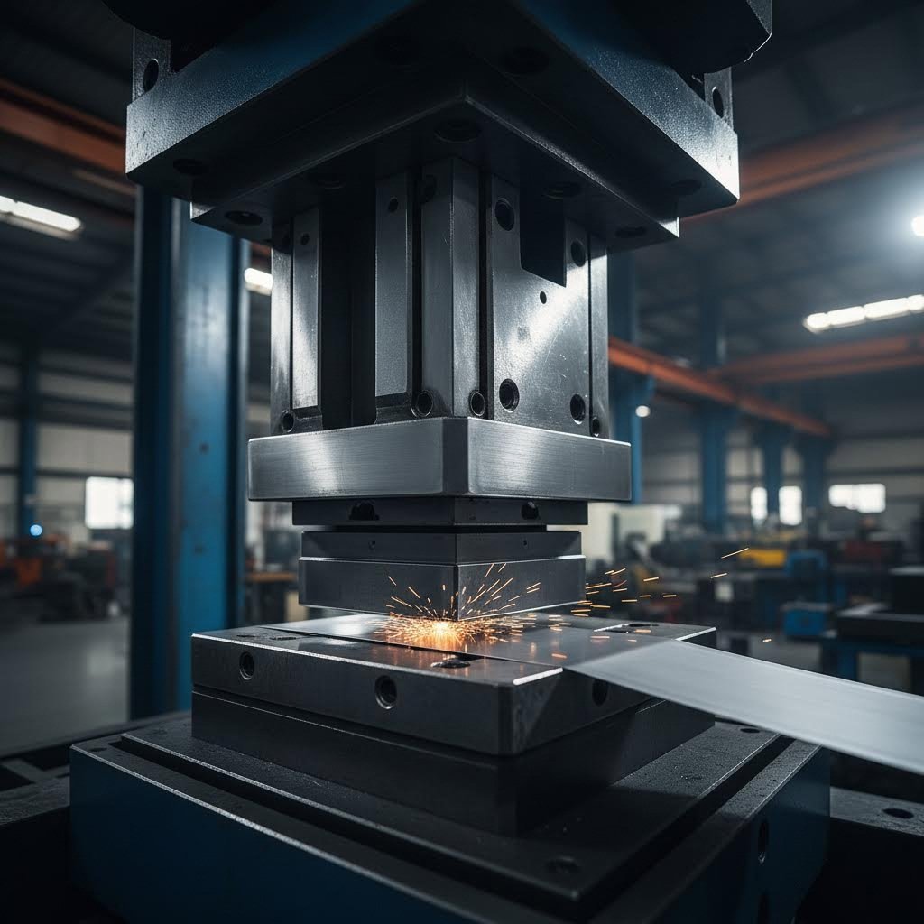
Ever wondered how manufacturers produce thousands of identical metal parts with remarkable speed and precision? The answer lies in a specialized tool called a metal stamping die. So, what is dies in manufacturing? Simply put, a stamping die is a custom-built precision tool designed to cut and form sheet metal into a specific shape or profile. When you ask "what is metal stamping," you're really asking about a cold-forming process where controlled force transforms flat metal sheets into complex components—everything from tiny electronics parts that fit in your palm to massive automobile body panels.
The magic happens when a die for press is mounted inside a stamping press. The press delivers tremendous force, enabling the die to perform its cutting and forming operations with exceptional accuracy. According to The Fabricator, stamping dies can cycle as fast as 1,500 strokes per minute, producing multiple piece parts with each cycle. That's the kind of efficiency that makes modern mass production possible.
The Core Function of Stamping Dies
What is a stamping operation at its core? It's the collaboration between three essential elements: the punch, the die block, and the press. The punch is the upper component that descends with force, while the die block sits below, containing precisely machined cavities that shape the metal. The press provides the controlled power needed to drive these components together.
When metal is placed between these tool steel sections, the punch forces it into or through the die block. This interaction can cut material cleanly, bend it into angles, or draw it into complex three-dimensional shapes. The cutting and forming sections are typically made from hardened tool steel or carbide materials designed to withstand repeated high-force impacts.
Why Precision Tooling Drives Manufacturing Success
Understanding what is stamping helps you appreciate why precision tooling matters so much. Every dimension of a stamping die must be exact—tolerances often measured in thousandths of an inch determine whether parts meet specifications or become scrap. The precision stamping tools used in modern manufacturing enable complex geometries, minimize material waste, and ensure product uniformity across millions of parts.
In this article, you'll journey from these foundational concepts to practical applications. We'll explore different die types and selection criteria, examine critical components and their functions, dive into tool steel selection, and uncover maintenance strategies that extend die life. Whether you're new to pressworking or looking to deepen your expertise, this guide will equip you with actionable knowledge for real-world manufacturing success.
Types of Stamping Dies and How to Choose Between Them
Now that you understand the fundamentals, let's tackle a question that often trips up manufacturing engineers: which type of stamping die should you actually use? The answer isn't one-size-fits-all. Your choice depends on part complexity, production volume, material requirements, and budget constraints. Understanding the engineering rationale behind each die type will help you make smarter tooling investments.
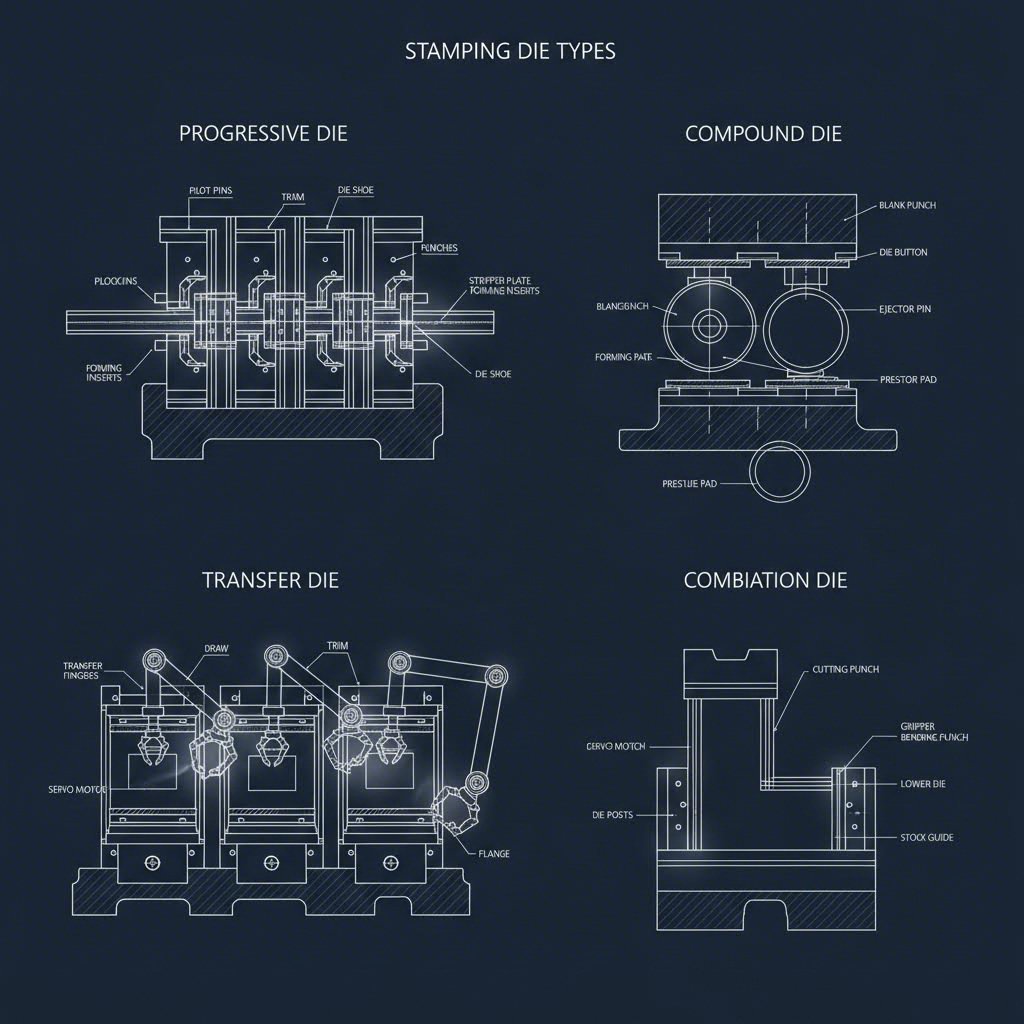
There are four primary types of stamping dies you'll encounter in precision die and stamping operations: progressive dies, compound dies, transfer dies, and combination dies. Each excels in specific scenarios, and choosing incorrectly can mean wasted tooling dollars or production bottlenecks.
| Die Type | Part Complexity | Production Volume | Material Thickness | Tooling Investment | Best Application |
|---|---|---|---|---|---|
| Progressive Dies | High (multiple operations) | High volume (100,000+ parts) | Thin to medium gauge | High initial cost | Automotive brackets, electronic components |
| Compound Dies | Low to medium | Low to medium volume | Thin to medium gauge | Moderate cost | Flat parts requiring tight tolerances |
| Transfer Dies | High (large, complex parts) | Medium to high volume | Medium to heavy gauge | High cost | Aerospace components, large automotive panels |
| Combination Dies | Medium to high | Medium volume | Varies by design | Moderate to high | Parts needing cutting and forming in one stroke |
Progressive Dies for High-Volume Efficiency
Imagine an assembly line where each station adds one more feature to your part—that's essentially how a progressive die works. The metal strip feeds through multiple stations arranged in sequence, with each station performing a specific operation: punching a hole, forming a bend, trimming an edge. By the time the strip exits the final station, a completed part drops off.
Why do progressive die manufacturers dominate high-volume production? Speed and consistency. According to Durex Inc., progressive dies are capable of producing large volumes of parts quickly while ensuring uniformity across all produced components. When you're stamping 500,000 brackets for an automotive assembly line, that uniformity matters enormously.
The trade-off? Progressive dies require significant upfront investment in stamping die design and tooling. However, the cost-per-part drops dramatically at high volumes, making them economically attractive for production runs exceeding 100,000 pieces. They're also limited to parts that can remain attached to the strip as it moves through stations—which brings us to situations where other die types shine.
When Compound Dies Outperform Progressive Designs
Sometimes simpler is smarter. Compound dies perform multiple operations in a single stroke, combining tasks like cutting and forming within one die set. This approach works beautifully for simpler, flatter parts where you need exceptional dimensional accuracy.
Here's the engineering rationale: when a compound stamp die executes all operations simultaneously, there's no opportunity for positional error between stations. The result is tighter tolerances and more consistent parts. As Worthy Hardware notes, compound dies are efficient in material usage, reducing scrap and cost—but they're not economical for complex parts requiring numerous operations.
Consider compound dies when you're producing:
- Flat blanks with precise dimensions
- Parts requiring simultaneous cutting and piercing
- Medium-volume runs where setup simplicity matters
- Components for medical devices or consumer electronics needing tight tolerances
Transfer Dies: Flexibility for Larger Parts
What happens when your part is too large to feed through a progressive die? Enter transfer dies. In this setup, individual parts are mechanically transferred from one stamping station to the next—think of it as a skilled handoff system where each station contributes something specific to the final product.
Transfer dies excel in dies and stamping applications involving larger, more complex parts that simply cannot remain attached to a strip. The Zintilon manufacturing guide explains that transfer dies utilize automated transfer mechanisms to move parts between different stations, making them ideal for highly automated production lines producing complex parts.
The flexibility comes with trade-offs: higher operational costs, longer setup times, and the need for skilled maintenance. But for aerospace components, heavy machinery parts, or large automotive panels, transfer dies often represent the only viable solution.
Making Your Selection Decision
Choosing between these types of stamping dies ultimately comes down to matching your specific requirements against each option's strengths. Ask yourself:
- What's your annual volume? High volumes favor progressive dies; lower volumes may justify compound or single-operation tooling.
- How complex is the part geometry? Multiple features and operations point toward progressive or transfer dies.
- What are your size constraints? Larger parts that can't feed through stations require transfer die solutions.
- What tolerances must you hold? Critical precision on flat parts often favors compound dies.
Understanding these decision factors transforms die selection from guesswork into engineering judgment. With the right tooling choice made, the next critical consideration becomes understanding what's actually inside these precision tools—the components that make everything work together.
Essential Die Components and Their Functions
You've selected the right die type for your application—now what makes it actually work? Inside every metal stamping die, a precisely engineered system of components works in concert to transform flat sheet metal into finished parts. Understanding these stamping die components isn't just academic knowledge; it's essential for troubleshooting problems, communicating with toolmakers, and making informed decisions about die design and maintenance.
Think of a stamping die as an orchestra. Each component plays a specific role, and when everything is perfectly tuned, the result is consistent, high-quality parts. When something's off—even by a few thousandths of an inch—the entire performance suffers. Let's examine the critical players in this precision ensemble.
Critical Components Inside Every Stamping Die
According to Moeller Precision Tool, die plates (also known as die shoes or die sets) serve as the foundation where other die tools and components are mounted. These steel or aluminum plates hold everything in place and provide the structural rigidity needed to withstand repeated high-force impacts. Without properly machined and aligned die shoes, nothing else can function correctly.
Here's a breakdown of the essential components you'll find in sheet metal stamping dies:
- Die Shoes (Die Plates): The structural foundation that mounts all other components. Upper and lower shoes must maintain precise alignment throughout millions of cycles.
- Guide Pins and Bushings: These alignment components are manufactured to tolerances within 0.0001" (one ten-thousandth of an inch) to ensure the upper and lower die halves meet with perfect precision every stroke.
- Punches: The cutting and forming tools that actually contact and transform the metal. Available in various nose shapes—round, oblong, square, hexagonal—depending on the required operation.
- Die Buttons: The counterpart to punches, providing the opposite cutting edge. Die buttons typically offset larger than the punch nose by 5-10% of the material thickness to create proper cutting clearance.
- Die Retainers: Components that hold punches and buttons in precise position. Quality retainers prevent stacking tolerance errors that degrade part accuracy.
- Die Springs: High-force compression springs that hold metal sheets in place during forming operations. Options include mechanical wire coil springs and nitrogen gas springs for higher force applications.
Each component in sheet metal dies must work within extremely tight tolerances. When a punch descends into a die button, the clearance between them—typically 5-10% of material thickness—directly determines edge quality, burr formation, and tool life. Too much clearance creates excessive burrs; too little causes premature wear and potential tool breakage.
How Pilots and Strippers Ensure Precision
Two components deserve special attention because they're often misunderstood: pilots and strippers. These elements are critical for consistent part quality in stamper dies, yet many operators don't fully appreciate their function.
Pilots are precision positioning elements that ensure accurate alignment before cutting begins. As Eabel's technical guide explains, a pilot punch enters a pre-punched hole to accurately position the strip, playing a key role in maintaining precision in progressive die operations. Without proper piloting, positional errors accumulate from station to station, resulting in out-of-tolerance parts.
Imagine feeding a metal strip through ten progressive stations. At each station, the strip must be positioned identically—within thousandths of an inch—to maintain part accuracy. Pilots accomplish this by physically guiding the strip into the correct position before any cutting or forming occurs.
Strippers perform an equally essential function: removing material from punches after each operation. When a punch pierces through metal, the material naturally wants to grip the punch as it retracts. Strippers—whether mechanical spring-loaded plates or urethane components—push the sheet off the punch, ensuring clean separation and preventing material from being pulled back into the die.
The stripper plate serves multiple purposes:
- Holds the sheet flat against the die surface during cutting
- Prevents material from sticking to the punch on the return stroke
- Maintains consistent strip feeding in progressive operations
- Protects pilots and punches from damage during material handling
Understanding Bypass Notches in Sheet Metal Forming
Here's a topic that confuses many newcomers to stamping: what exactly is the bypass notches sheet metal forming purpose? According to Eagle Metalcraft, bypass notches are used to prevent interference between forming sections of the die during the stamping process. Positive and negative notches allow clearance and help maintain structural integrity during forming.
Picture a progressive die where multiple forming operations occur in sequence. As the strip moves through the die, previously formed features—like a drawn cup or a bent flange—could interfere with subsequent stations. Bypass notches provide the necessary clearance for these formed features to pass through without collision or damage.
There are two types:
- Positive bypass notches: Raised sections in the die that allow formed features to pass over them
- Negative bypass notches: Recessed areas that provide clearance below the strip line
Without properly designed bypass notches, formed features would crash into subsequent die stations, damaging both the tooling and the parts. This seemingly simple design element is actually critical for enabling complex multi-station progressive die operations.
The Functional Hierarchy: How Components Work Together
Understanding individual components is important, but grasping how they function as a system is what separates competent operators from true tooling experts. The functional hierarchy works like this:
Die shoes provide the foundation and maintain alignment. Guide pins and bushings ensure the upper and lower shoes meet precisely with each stroke. Pilots position the material accurately before any operation begins. Punches and die buttons perform the actual cutting or forming work. Strippers remove the material cleanly. Springs provide the controlled force needed for holding and stripping operations.
When tolerance relationships break down anywhere in this chain, part quality suffers immediately. A worn guide bushing might allow only 0.002" of play—but that play translates directly into dimensional variation on your finished parts. Dull punch edges might still cut, but they'll produce unacceptable burrs and accelerate die button wear.
This interconnected system is precisely why proper maintenance protocols matter so much. A problem with one component rarely stays isolated; it cascades through the entire system, affecting part quality and tool life across the board.
Die Materials and Tool Steel Selection Guide
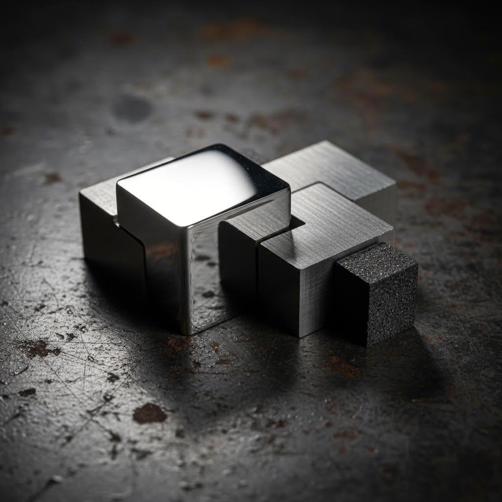
You've explored die types and components—but here's a question that separates average tooling from exceptional performance: what material should your metal stamping die actually be made from? The answer directly impacts how long your die lasts, how consistently it performs, and ultimately how much each part costs to produce. Get this decision wrong, and you'll face premature wear, frequent sharpening, or catastrophic tool failure. Get it right, and your steel stamping dies will deliver millions of quality parts.
Material selection isn't guesswork—it's engineering. Different stamping applications demand different material properties. A die punching thin aluminum for electronics requires different steel characteristics than one forming thick stainless steel for automotive chassis components. Understanding the trade-offs between hardness, toughness, and wear resistance will help you specify the right tool steel for every application.
Tool Steel Selection for Different Stamping Applications
When machining dies for stamping operations, four primary tool steel grades dominate the industry. Each offers a distinct balance of properties suited to specific production requirements. According to the AOBO Steel technical guide, the selection of appropriate tool steel directly determines the tool's service life and the final quality of the parts, thereby impacting the enterprise's overall production costs.
| Steel Grade | Hardness (HRC) | Toughness | Wear Resistance | Best Applications |
|---|---|---|---|---|
| D2 | 58-60 | Low-Medium | Excellent | High-volume blanking, long-run production (100,000+ pieces) |
| A2 | 58-60 | Medium-High | Good | Medium-batch stamping, balanced performance needs |
| S7 | 54-58 | Excellent | Low-Medium | Heavy-duty blanking, high-impact applications, thick plate forming |
| M2 | 60-65 | Medium | Excellent | Cutting difficult materials like stainless steel, dies exceeding 100,000 cycles |
D2 Tool Steel: This is the workhorse of metal stamping dies in high-volume applications. D2 delivers exceptional wear resistance thanks to its high chromium content (11-13%). As the Alro Tool & Die Steel Handbook notes, D2 has extremely high wear resistance and excellent size stability in heat treatment—making it ideal for blanking, stamping, and cold forming dies where emphasis is not on toughness. The trade-off? D2's toughness is relatively limited, so it's not your first choice for heavy shock loads.
A2 Tool Steel: When you need a balance between wear resistance and toughness, A2 delivers. This medium-alloy air-hardening steel offers toughness superior to the D series and wear resistance better than oil-hardening O-series steels. A2 exhibits exceptional dimensional stability during heat treatment with minimal deformation, making it a reliable choice for medium-batch stamping dies requiring hardness between 58-60 HRC.
S7 Tool Steel: Heavy forming operations that generate significant shock loads demand S7's exceptional toughness. This air-quenching steel combines high toughness with dimensional stability, making it ideal for heavy-duty blanking dies and shearing tools. According to industry data, S7 can withstand extremely high impact loads with typical hardness ranging from 54-58 HRC. When thick plate materials (exceeding 6.4mm) threaten to crack or chip your punches, S7 provides the resilience you need.
M2 High-Speed Steel: For custom metal stamping dies cutting difficult-to-machine materials like stainless steel, M2 offers superior edge retention. This molybdenum-based high-speed steel maintains a stable working hardness of 60-65 HRC and provides outstanding resistance to edge chipping compared to D-series steels. M2 is highly suitable for long-life dies exceeding 100,000 cycles where edge quality is critical.
Matching Steel Grade to Production Volume
Production volume dramatically influences which die stamp material makes economic sense. Here's a practical framework:
- Short runs (under 10,000 pieces): Focus on controlling material and machining costs. Low-alloy steels like O1 offer excellent machinability at reasonable cost. These materials provide adequate performance for limited production without excessive tooling investment.
- Medium runs (10,000 to 100,000 pieces): A2 steel strikes the optimal balance between wear resistance and dimensional stability. It meets production demands at this scale while offering high cost-effectiveness.
- Long runs (100,000+ pieces): D2 becomes the standard choice for high-volume stamping. For even higher output requirements or difficult materials, upgrading to M2 high-speed steel extends service life significantly.
When Carbide Inserts Justify the Investment
Sometimes even the best tool steels aren't enough. For extreme wear situations—highly abrasive materials, ultra-high production volumes, or critical tolerance requirements—carbide inserts offer a solution that die stamps made from conventional steels simply can't match.
Carbide (tungite carbide in a cobalt matrix) provides wear resistance orders of magnitude higher than tool steel. However, carbide's brittleness means it cannot handle significant impact loads. This creates a clear decision framework:
Consider carbide inserts when wear resistance is the primary concern and impact loads are minimal. For applications involving significant shock or thick materials, even premium carbides will fracture—making tough tool steels like M2 or S7 the better choice despite lower wear resistance.
The cost-benefit calculation for carbide involves several factors:
- Initial cost: Carbide inserts cost 3-10x more than equivalent tool steel components
- Service life: Properly applied carbide can outlast tool steel by 5-20x in abrasive applications
- Maintenance: Carbide requires specialized grinding equipment and techniques
- Risk: Carbide fractures catastrophically rather than wearing gradually, potentially damaging expensive die components
For materials causing extreme mold wear—such as high-silicon electrical steel or stainless steel—premium carbide grades like CPM 10V or M4 leverage their high vanadium carbide content to extend service life significantly. These specialized applications often justify the substantial investment.
Hardness Requirements and Heat Treatment Considerations
Proper heat treatment transforms raw tool steel into a high-performance die component. For punches in metal stamping dies, hardness typically targets 58-62 HRC (Rockwell C scale). This range provides the edge retention needed for clean cutting while maintaining enough toughness to resist chipping.
Different die components often require different hardness levels within the same tool:
- Punches: 60-62 HRC for maximum cutting performance and edge retention
- Die buttons: 58-60 HRC, slightly softer than punches to prevent galling
- Strippers and pressure pads: 45-52 HRC for impact absorption without deformation
- Die shoes: 28-35 HRC or left unhardened for machinability and shock absorption
Heat treatment involves precise temperature control and timing. For example, D2 requires preheating at 1200-1300°F before hardening at 1850-1875°F, followed by tempering at 950-975°F for optimal balance between hardness and toughness. Improper heat treatment—too fast, too hot, or insufficient tempering—causes cracking, distortion, or soft spots that compromise die performance.
The differentiated material selection for punches versus die bases reflects their different failure modes. Punches experience the most concentrated stress and are most prone to toughness failure. For heavy-duty applications, S7 or A2 is recommended for punches, while die bases can utilize D2 or carbide inserts to ensure overall durability.
With the right tool steel selected and properly heat treated, your die has the foundation for excellent performance. But even the best materials can't compensate for incompatibility with the sheet metal being stamped—which brings us to the critical topic of material matching and die configuration adjustments.
Material Compatibility and Die Configuration Adjustments
You've selected the perfect tool steel for your die—but here's the catch: that same die configuration won't work equally well for every sheet metal you stamp. Aluminum behaves completely differently than stainless steel. Copper flows unlike carbon steel. Each material brings unique properties that demand specific adjustments to clearances, forming geometry, and lubrication strategies. Ignore these differences, and you'll face burrs, galling, cracked parts, and frustrated operators.
Understanding the stamping metal process for different materials isn't optional knowledge—it's the difference between consistent quality and endless troubleshooting. Let's explore how material properties drive die configuration decisions and what adjustments you need for the most common sheet metals.
How Material Properties Drive Die Design Decisions
Three material characteristics fundamentally influence how you configure a metal stamping die: tensile strength, ductility, and work hardening behavior. These properties determine everything from punch-to-die clearance to springback compensation.
- Tensile Strength: Higher-strength materials require greater forming forces and harder tooling. Stainless steel's tensile strength (typically 75,000-100,000 psi) demands significantly more press tonnage than mild steel (45,000-65,000 psi).
- Ductility: Materials with higher ductility—like copper and aluminum—stretch more before fracturing, allowing deeper draws but requiring careful control of material flow.
- Work Hardening: Some materials become significantly harder as they're formed. Stainless steel work hardens aggressively, meaning each forming operation increases resistance to subsequent operations.
The relationship between these properties and die clearance is critical. Clearance—the gap between punch and die button—directly affects edge quality, tool life, and forming forces. Too little clearance causes excessive wear and potential tool breakage. Too much creates unacceptable burrs and edge rollover.
| Material | Recommended Clearance (% of thickness) | Key Characteristics | Primary Challenge |
|---|---|---|---|
| Aluminum (soft) | 3-5% | Low strength, high ductility | Galling, burr control |
| Copper/Brass | 4-6% | Excellent ductility, moderate work hardening | Material pickup on tooling |
| Mild Carbon Steel | 5-8% | Balanced properties, predictable behavior | Standard baseline material |
| Stainless Steel (300 series) | 6-10% | High work hardening, high strength | Severe galling, springback |
| High-Strength Steel | 8-12% | Very high strength, limited ductility | Extreme springback, tool wear |
Aluminum Stamping Considerations and Die Adjustments
The aluminum stamping process presents unique challenges that catch many toolmakers off guard. Aluminum's softness might seem like it would be easy to stamp—but that softness creates its own set of problems.
Aluminum stamping dies require tighter clearances (3-5% of material thickness) compared to steel because aluminum's lower shear strength produces cleaner edges with less clearance. However, that same softness makes aluminum prone to adhesive galling—where aluminum particles weld themselves to the tool steel surface.
Key considerations for stamping aluminum:
- Surface finish matters: Highly polished punch and die surfaces reduce friction and minimize galling tendency.
- Coating selection: TiN (titanium nitride) or DLC (diamond-like carbon) coatings significantly reduce aluminum's tendency to stick to tooling.
- Lubrication is critical: Use lubricants specifically formulated for aluminum stamping—petroleum-based lubricants often react poorly with aluminum alloys.
- Clearance consistency: Aluminum's softness makes it sensitive to clearance variations—maintain tighter tolerances on punch-to-die alignment.
- Springback compensation: Aluminum exhibits moderate springback, typically requiring 2-4 degrees of overbend in forming operations.
Stamped sheet metal parts in aluminum also require careful handling to prevent surface scratching. Many operations incorporate protective films or specialized stripper materials to preserve cosmetic surfaces.
Stainless Steel Challenges in Die Design
If aluminum is deceptively tricky, stainless steel is openly difficult. This material combines high strength, aggressive work hardening, and severe galling tendencies—a challenging combination for any metal stamping and forming operation.
According to die science research, adhesive galling occurs when the tool steel and the sheet metal have similar metallurgical properties. When two like metals rub together, friction creates heat that can actually cause the surfaces to melt together—commonly called cold welding.
Preventing galling in stainless steel stamping requires a multi-pronged approach:
- Tool steel selection: CPM 10V and AMPCO (aluminum bronze) resist galling better than conventional D2 or A2 steels.
- Duplex coatings: Combining plasma nitriding with PVD coatings (like TiAlN or CrN) creates surfaces that resist both abrasive and adhesive wear.
- Increased clearance: Stainless steel requires 6-10% clearance to reduce the friction that triggers galling.
- Lubricant selection: High-pressure lubricants with extreme pressure (EP) additives are essential—standard stamping oils won't survive the forces involved.
- Reduced forming speed: Slower press speeds reduce heat generation that accelerates galling.
Springback Compensation Across Materials
Every stamped part tries to return to its original shape after forming—this elastic recovery is springback, and it varies dramatically by material. According to ETA's technical guide, the ratio of yield strength to Young's Modulus is a key indicator of springback potential. For high-strength steels, this ratio is considerably higher, meaning a larger portion of the total deformation is elastic and will be recovered.
Sheet metal stamping operations must account for springback through deliberate die geometry adjustments:
- Overbending: Intentionally forming past the target angle so the part springs back to specification.
- Coining: Applying localized high pressure at bend radii to plastically deform material and reduce elastic recovery.
- Die compensation: Using FEA simulation to predict springback and modify tool geometry accordingly.
High-strength steels and stainless steel exhibit the most severe springback—sometimes requiring 5-10 degrees of overbend. Mild steel and aluminum show more moderate springback, while copper and brass typically exhibit the least elastic recovery due to their lower yield strength ratios.
Accurate springback prediction through simulation reduces physical die tryouts from weeks to days—transforming what was once trial-and-error into predictive engineering.
Understanding these material-specific requirements transforms your approach to die configuration. But even perfectly configured dies require ongoing attention—which brings us to the maintenance strategies that keep your tooling performing at its best throughout its service life.
Die Maintenance and Lifespan Optimization Strategies
Your metal stamping die is performing beautifully today—but what about after 50,000 hits? 500,000? Here's the uncomfortable truth: even the finest tool steel and perfect clearances mean nothing without proper maintenance. A neglected die doesn't just wear out faster; it produces quality defects, creates production delays, and ultimately costs far more than any preventive maintenance program ever would.
According to Phoenix Group's manufacturing research, poor die maintenance causes quality defects during production, driving up sorting costs, increasing the likelihood of shipping defective parts to customers, and risking expensive forced containments. The hidden costs multiply quickly: scrap material, shortened production runs, emergency repairs under the press, and downstream assembly problems caused by dimensional variation.
Think of die maintenance as insurance that pays dividends. Every hour invested in preventive care returns multiple hours of uninterrupted production. Let's explore the protocols that keep your stamping tooling performing at peak levels throughout its service life.
Preventive Maintenance Schedules That Extend Die Life
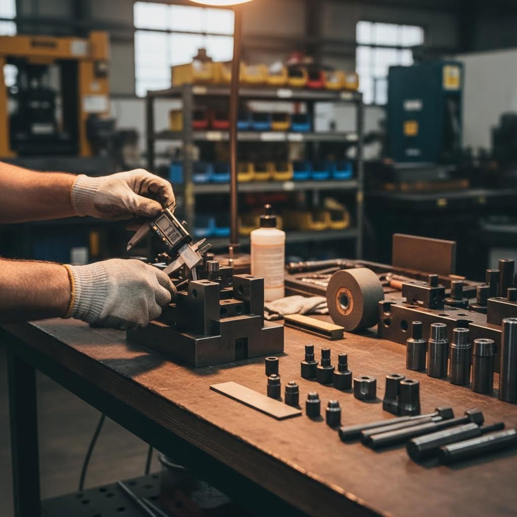
Effective stamp and die maintenance follows a systematic approach—not random inspections when problems appear. The goal is catching issues before they affect part quality or cause unplanned downtime. Here's a structured maintenance procedure based on industry best practices:
- Conduct visual inspections: Examine all working surfaces for wear patterns, cracks, chipping, or damage. Pay close attention to cutting edges and forming surfaces where wear concentrates.
- Measure critical dimensions: Use precision instruments to verify punch diameters, die button openings, and clearances. Document measurements against baseline specifications to track dimensional drift.
- Verify punch and die clearance: Check that clearances remain within specification. Clearance increases as cutting edges wear—when clearance exceeds 15-20% of material thickness, burrs become unacceptable.
- Inspect alignment components: Examine guide pins, bushings, and heel blocks for wear. Even 0.001" of play in alignment components translates directly into part dimensional variation.
- Check springs and strippers: Verify spring force meets specification. Weakened springs cause inconsistent stripping and potential material handling problems.
- Clean and lubricate: Remove debris, slugs, and lubricant buildup. Apply fresh lubricant to all moving components and working surfaces.
- Document findings: Record all observations, measurements, and work performed. This data enables trend analysis and predictive maintenance.
The frequency of these inspections depends on production volume and material type. According to The Fabricator's maintenance guidelines, high-volume stamp dies—those made for long production runs—typically require maintenance on a weekly or biweekly basis to keep inventory levels in check and pipeline activity at an even keel.
Sharpening Intervals and Component Reconditioning
Cutting components are consumables—they require regular sharpening to maintain edge quality. But how often? The answer varies significantly based on material type and production volume:
- Mild steel: Sharpen every 20,000-50,000 hits under normal conditions
- Stainless steel: Sharpen every 10,000-25,000 hits due to higher work hardening and abrasiveness
- Aluminum: Sharpen every 25,000-50,000 hits, but inspect for galling more frequently
- High-strength steel: Sharpen every 10,000-20,000 hits due to extreme tool wear
These intervals are starting points—actual sharpening needs depend on specific material grades, thicknesses, and part geometry. As industry experts recommend, saving the last part and last strip for inspection when the tool goes in for maintenance helps determine if extra actions may be needed beyond standard procedures.
Proper sharpening involves more than just grinding material away. The process must restore original geometry while maintaining proper edge conditioning. Each sharpening cycle removes material, so corresponding shims must compensate for the dimensional change. Dies manufacturing best practices suggest organizing shims by thickness—creating packages containing every shim size for that particular component—to streamline the maintenance process.
Recognizing Early Warning Signs of Die Wear
Waiting for obvious problems means you've already lost production quality. Skilled operators learn to recognize subtle indicators that maintenance is needed before defects appear:
- Increasing burr height: Burrs grow progressively as cutting edges dull and clearances increase. Measure burr height regularly against acceptable limits.
- Dimensional drift: Parts slowly moving toward tolerance limits indicate wear on forming surfaces or alignment components.
- Increased forming force: Rising tonnage readings suggest friction from worn or galled surfaces.
- Surface quality changes: Scratches, galling marks, or inconsistent finishes signal tooling problems.
- Noise changes: Experienced operators can hear when a die starts running differently—unusual sounds often precede visible problems.
According to JVM Manufacturing's technical guidance, advanced techniques such as ultrasonic testing or magnetic particle inspection can identify subsurface flaws not visible to the naked eye, ensuring comprehensive assessment of steel stamping tools before problems reach the surface.
Die Storage, Rust Prevention, and Handling Protocols
Maintenance doesn't end when the die leaves the press. Proper storage prevents corrosion, contamination, and handling damage that can undo all your preventive efforts:
- Clean thoroughly before storage: Remove all lubricant residue, chips, and debris. Contamination attracts moisture and accelerates corrosion.
- Apply rust preventive: Coat all working surfaces with appropriate rust preventive compounds. Choose products compatible with your stamping lubricants to avoid contamination issues at startup.
- Store in controlled environment: Maintain stable temperature and humidity. Avoid locations with condensation risk or temperature swings.
- Protect precision surfaces: Use covers or protective materials to prevent accidental damage during handling and storage.
- Document storage location: Track die locations in your inventory system for efficient retrieval when production resumes.
Handling protocols matter equally. Always use appropriate lifting equipment rated for the die weight. Never drag dies across surfaces—this damages precision-ground faces. Secure dies properly during transport to prevent shifting that could damage alignment components.
The Refurbishment Decision: Sharpen, Replace, or Retire
Every stamping die manufacturers' customer eventually faces this decision: when does maintenance no longer make sense? The answer requires balancing repair costs against replacement costs and remaining service life.
Sharpen when:
- Cutting edges are dull but geometry remains within specification
- Sufficient material remains for multiple sharpening cycles
- Shim stack height hasn't exceeded practical limits
- Part quality can be restored to specification
Replace components when:
- Wear exceeds what sharpening can restore
- Shim stacks become impractically tall
- Clearances have grown beyond correction
- Component geometry has been compromised
Retire the die when:
- Die shoes show fatigue cracks or distortion
- Alignment components cannot maintain required precision
- Repair costs approach new die construction costs
- The part design has changed, making the die obsolete
Track total hits on every die in your tool log. When unexpected breakdowns occur, this data helps predict component life and schedule preventive replacements before failure—transforming reactive firefighting into proactive management.
A systematic approach to dies manufacturing maintenance extends tool life significantly while maintaining consistent part quality. But even the best-maintained die eventually encounters problems that require troubleshooting expertise—which brings us to diagnosing and solving common die issues before they derail production.
Troubleshooting Common Die Problems and Part Defects
Your maintenance program is solid, your tool steel is correct, your clearances are dialed in—yet defects still appear. What's happening? The reality is that even well-designed metal stamping dies encounter problems during production. The difference between experienced operators and novices isn't avoiding problems entirely; it's diagnosing root causes quickly and implementing effective solutions before quality suffers.
According to Jeelix's technical analysis, stamping is a complex system where multiple variables interact dynamically—even the slightest fluctuation can trigger a chain reaction that ultimately manifests as a product defect. This means traditional single-point troubleshooting often hits walls because defects rarely have single causes.
Think of troubleshooting as detective work. Every symptom tells a story, and your job is reading the clues correctly. Let's examine the most common die stamping problems, trace them to their root causes, and outline proven solutions.
Diagnosing Burr Formation and Clearance Issues
Burrs are perhaps the most common defect in the metal stamping process—those raised edges or material remnants along cut lines that shouldn't exist. When burrs appear on die stamped parts, they signal problems with your cutting operation that demand immediate attention.
What causes burrs to form? The physics is straightforward: when a punch shears through material, the metal fractures cleanly only if clearance and edge sharpness are correct. Deviate from ideal conditions, and material tears rather than shears—leaving burrs behind.
Common causes of excessive burring include:
- Excessive clearance: As cutting edges wear, the gap between punch and die increases. Clearance beyond 15% of material thickness typically produces unacceptable burrs.
- Dull cutting edges: Worn punches and die buttons require more force to cut, causing material to roll over edges rather than shear cleanly.
- Misalignment: When punch and die don't meet concentrically, one side cuts with proper clearance while the other has excessive clearance—creating uneven burrs.
- Incorrect initial clearance: Die design that specified wrong clearance for the material being stamped.
According to Leelinepack's manufacturing research, burrs usually come from too much tool wear or misalignment in stamping—leaving small fragments on the metal's edges. The solution depends on the root cause: sharpening restores dull edges, realignment corrects concentricity, and adjusting die clearance addresses specification errors.
Solving Galling Problems in Stainless Steel Stamping
Galling is one of the most frustrating problems in metal stamping techniques—and it's especially severe with stainless steel and aluminum. This adhesive wear mechanism occurs when material transfers from the sheet metal onto the die surface, creating rough spots that progressively worsen with each stroke.
According to die science research, scoring refers to deep scratches aligned with the drawing direction on a part's surface, while galling is the transfer and cold welding of small material particles from the sheet onto the die surface—often the root cause of scoring. Galling quickly worsens surface finish and accelerates die wear, creating a damaging feedback loop.
Galling signals inadequate lubrication, material incompatibility, or surface finish problems. The solution requires a multi-dimensional approach:
- Improve lubrication: Switch to high-pressure lubricants with extreme pressure (EP) additives specifically formulated for your material.
- Apply coatings: TiN, DLC, or CrN coatings on tooling surfaces dramatically reduce adhesive transfer.
- Polish die surfaces: Mirror-finished working surfaces minimize friction that triggers galling.
- Reduce forming speed: Lower press speeds reduce heat generation that accelerates cold welding.
- Consider alternative tool materials: Aluminum bronze (AMPCO) or CPM 10V steel resist galling better than conventional D2.
Mapping Symptoms to Causes and Solutions
Effective troubleshooting requires systematic thinking. The following table maps common stamped parts defects to their likely causes and proven solutions—giving you a diagnostic framework for rapid problem resolution:
| Symptom | Likely Causes | Solutions |
|---|---|---|
| Excessive burrs | Dull cutting edges, excessive clearance, punch/die misalignment | Sharpen cutting components, verify clearance, check alignment |
| Galling/scoring | Inadequate lubrication, material incompatibility, rough tool surfaces | Upgrade lubricant, apply tool coatings, polish working surfaces |
| Dimensional variation | Worn guide components, thermal expansion, material thickness variation | Replace guides/bushings, control temperature, verify incoming material |
| Cracking/splitting | Insufficient material ductility, excessive forming severity, sharp die radii | Increase forming radii, add forming stations, verify material properties |
| Wrinkling | Insufficient blank holder force, excessive clearance, poor material flow | Increase blank holder pressure, optimize draw beads, adjust clearance |
| Springback | High material strength, insufficient overbend, elastic recovery | Increase overbend angle, add coining operations, use simulation to optimize |
| Premature tool wear | Wrong tool steel selection, improper heat treatment, abrasive material | Upgrade steel grade, verify heat treatment, apply wear coatings |
| Uneven wear patterns | Misalignment, unbalanced forces, off-center loading | Realign die components, balance forming forces, center workpiece |
Part Defects Traceable to Die Issues
Every defect in the stamping process tells a story about what's happening inside your die. Learning to read these stories transforms reactive troubleshooting into systematic problem-solving.
Dimensional variation is often the most costly defect because parts may appear acceptable but fail at assembly. When stamped parts drift toward tolerance limits—or exceed them—the cause typically lies in worn alignment components. Guide pins and bushings that allow even 0.002" of play translate directly into part dimensional error. Thermal expansion during long production runs can also cause dimensional drift as die components grow slightly with heat.
Surface quality problems indicate friction-related issues. Scratches aligned with forming direction suggest galling or rough die surfaces. Orange peel texture on stretched surfaces indicates the material is being formed beyond its limits. Die lines—scratches perpendicular to material flow—signal debris trapped between tool and workpiece.
Inconsistent forming creates parts that vary from piece to piece despite identical press settings. According to Keysight's engineering research, variations in material properties, even within the same batch, can impact the eventual part quality—making it difficult to maintain tight tolerances and meet quality standards. When material properties fluctuate, previously stable processes produce variable results.
How CAE Simulation Prevents Problems Before Production
Here's a paradigm shift in die troubleshooting: what if you could identify and solve problems before cutting any steel? Computer-Aided Engineering (CAE) simulation makes this possible by creating virtual die try-outs that predict defects before physical tooling exists.
According to simulation research, part and process design can significantly affect quality, with defects emerging only during the first trials in the try-out stage of die manufacturing—when corrections are both time-consuming and costly. Simulation moves this discovery phase into the virtual world where changes cost nothing.
Modern forming simulation software can predict:
- Thinning and cracking risk: Identify areas where material will stretch beyond safe limits
- Wrinkling tendency: Detect regions where compressive stresses will cause material instability
- Springback magnitude: Calculate elastic recovery and determine required compensation
- Optimal blank shape: Determine the starting blank geometry that minimizes material usage while ensuring complete forming
- Process parameter windows: Find robust settings that maintain quality despite material variation
CAE simulation transforms troubleshooting from reactive firefighting into proactive prevention—solving problems in hours of computer time rather than weeks of physical die modification.
The investment in simulation pays dividends across the entire die lifecycle. Initial design benefits from optimized geometry and process parameters. Die tryout proceeds faster because major issues were resolved virtually. Production runs more consistently because the process window was validated before metal ever touched tooling.
For organizations serious about achieving zero-defect stamping, simulation capability is no longer optional—it's essential infrastructure. When combined with robust maintenance programs and systematic troubleshooting skills, simulation completes the toolkit for consistent, high-quality production. With these fundamentals mastered, you're ready to tackle the most demanding applications—like automotive stamping, where quality requirements reach their most stringent levels.

Automotive Stamping Die Requirements and Quality Standards
Your vehicle contains hundreds of metal stamped parts—from brake brackets that absorb crash forces to battery terminals that power every electrical system. Now imagine if just one of those parts fails due to a defective die. According to Step Metal Works, a single defective bracket, clip, or connector can trigger a recall costing millions. That's the reality of automotive stamping, where the stakes couldn't be higher.
Automotive applications push metal stamping die requirements to their absolute limits. Every component must meet tolerances measured in microns, perform flawlessly through temperature extremes, and survive years of vibration and stress. Understanding what separates automotive-grade tooling from standard industrial dies helps you appreciate why this sector demands such rigorous standards—and why partnering with the right stamping dies manufacturer matters so much.
Meeting Automotive OEM Tolerance Requirements
When OEMs specify tolerances for automotive stamping dies, they're not being arbitrary—they're responding to safety requirements and assembly constraints that leave zero room for error. Critical safety components like seat belt anchors, airbag housings, and brake parts require tolerances of ±0.002 inches or tighter. Functional assemblies like engine mounts and suspension brackets run ±0.005 to ±0.010 inches. Even non-critical parts like interior trim clips must stay within ±0.015 inches.
Why such precision? Consider how automotive assembly lines operate. Parts must fit together consistently across thousands of vehicles per day. A bracket that's 0.005" off specification might assemble fine on the first unit but create interference problems as tolerances stack up. When you're producing 300 to 500 stamped components per vehicle—and each vehicle must perform identically—consistency becomes non-negotiable.
Custom automotive metal stamping demands more than just hitting specifications on individual parts. OEMs require documentation proving every part meets requirements before it touches an assembly line. This includes dimensional reports from CMM measurements, material certifications confirming composition and properties, and statistical process control data demonstrating consistent production.
The automotive stamping die design process itself must account for these demands. Engineers use CAE simulation to predict defects before cutting any tool steel—identifying potential thinning, cracking, wrinkling, and springback issues during the virtual design phase. This predictive approach dramatically reduces physical try-outs and accelerates first-pass approval. Suppliers like Shaoyi leverage advanced CAE simulation to achieve a 93% first-pass approval rate, demonstrating how technology transforms metal stamping die design from trial-and-error into predictive engineering.
Quality Certifications That Matter for Automotive Tooling
Want to supply metal stamped parts to major automakers? Without proper certifications, you won't even get a meeting. The automotive industry has standardized quality requirements to ensure consistent performance across global supply chains.
IATF 16949 certification is the baseline for any serious automotive supplier. According to Master Products, this specialized certification aims to harmonize the many different certification programs and quality assessment systems used throughout the global automotive industry. Originally drafted in 1999 by the International Automotive Task Force, IATF 16949 creates a baseline for the quality you can expect when contracting out your automotive metal stamping project.
What does IATF 16949 actually require? The standard focuses on three primary aims:
- Continuous improvement: Systems for improving both product quality and manufacturing processes, reducing production costs and enhancing sustainability
- Defect prevention: Emphasis on preventing variances and minimizing scrap and waste throughout production
- Supply chain reliability: Establishing "supplier of choice" status through proven consistency and accountability
PPAP (Production Part Approval Process) documentation proves your metal stamped parts meet all engineering requirements. You'll submit dimensional reports, material certifications, process flow diagrams, and control plans. First article inspection catches tooling issues before production begins—saving both time and money.
Statistical process control monitors dimensions during production runs, tracking key features and flagging trends before parts drift out of specification. This prevents scrap and catches tool wear early, maintaining the consistency that automotive OEMs demand.
Rapid Prototyping and Development Acceleration
Speed matters in automotive development. Model years are compressed, electric vehicle platforms evolve rapidly, and getting tooling wrong delays entire programs. This creates intense pressure for rapid prototyping capabilities that compress development timelines without sacrificing quality.
Traditional die development cycles stretched 8-12 weeks from design to first parts. Today's competitive environment demands faster turnarounds. Progressive stamping dies manufacturer partners now offer prototype tooling in as little as 5 days—enabling design validation before committing to production tooling. Shaoyi's rapid prototyping capabilities exemplify this acceleration, compressing development cycles while maintaining the precision automotive applications demand.
First-pass approval metrics indicate engineering competence more clearly than any sales pitch. When a supplier consistently achieves 90%+ first-pass approval rates, they're demonstrating that their automotive stamping die design process works—that simulation accurately predicts real-world performance, that tolerances are properly specified, and that manufacturing execution matches engineering intent.
A 93% first-pass approval rate means fewer die modifications, shorter development cycles, and faster time-to-market—translating directly into competitive advantage for OEM customers.
Choosing the Right Automotive Die Partner
Not every stamping supplier can meet automotive requirements. When evaluating potential partners for custom automotive metal stamping, consider these critical factors:
- Certification status: IATF 16949 certification is non-negotiable for major OEM supply. Request copies of current certifications and recent audit results.
- Engineering capabilities: Look for CAE simulation, DFM analysis, and in-house tool design. Partners who catch issues before tooling is built save you time and money.
- Prototyping speed: Ask about typical turnaround times for prototype parts. Compressed development cycles require responsive partners.
- Quality metrics: Request first-pass approval rates, PPM defect rates, and on-time delivery performance. These numbers reveal true capabilities.
- Secondary operations: Can they handle deburring, tapping, welding, and assembly? Consolidated capabilities simplify your supply chain.
For manufacturers seeking comprehensive automotive stamping die solutions backed by IATF 16949 certification and proven engineering expertise, exploring specialized suppliers like Shaoyi's automotive stamping division provides insight into what integrated, quality-focused tooling partnerships look like in practice.
Automotive stamping represents the pinnacle of die requirements—but achieving these standards requires more than just technical capability. The economics of tooling investment play an equally critical role in project success, which brings us to understanding how to evaluate die costs against production realities.
Cost Analysis and Tooling Investment Decisions
You've mastered die types, materials, maintenance, and quality standards—but here's the question that ultimately drives every tooling decision: what will this actually cost, and is the investment justified? Surprisingly, most manufacturers approach die costs with incomplete information. They focus on the initial quote while ignoring the factors that truly determine whether a tooling investment pays off.
According to The Fabricator's die science research, there is no perfect formula or equation for deriving tooling cost, but numerous factors can be considered to help increase estimate accuracy. Understanding these factors transforms cost discussions from guesswork into strategic decision-making.
Understanding Tooling Investment Versus Production Volume
The relationship between tooling cost and production volume is straightforward in principle but often misunderstood in practice. Higher production volumes justify larger tooling investments because the cost spreads across more parts. But how do you calculate whether that premium die makes economic sense?
Several factors drive custom metal stamping die investment levels:
- Part complexity: Progressive dies with multiple stations cost significantly more than single-station tools. According to industry data, complex dies need to be designed so that a carrier strip can be made, fed, and properly sequenced through each station—adding engineering time and material costs.
- Die size: Larger dies require more tool steel, longer machining time, and bigger presses. Automotive body panel dies can cost 10-20 times more than small bracket tooling.
- Material requirements: Dies made from premium tooling materials such as carbide take more time to manufacture because the material requires more time to machine and must be wire-burned and diamond-finished.
- Precision requirements: Parts with tight or small tolerancing require additional stations and higher-grade tool steels, raising costs accordingly.
- Expected production volume: High-volume dies typically use larger, thicker, and higher-quality tool steel sections, while low-volume dies might use less expensive materials or even cast composites.
Die class designations help frame these investment decisions. Class A dies are designed for high production and ease of maintenance—capable of producing extreme volumes where additional tooling cost becomes insignificant per part. Class B dies serve smaller volumes with limited life expectancy. Class C dies typically handle short-term prototype applications.
Cost-Per-Part Calculations and Amortization
The true measure of tooling economics isn't the purchase price—it's the cost per part over the die's productive life. A $50,000 die producing 1,000,000 parts costs $0.05 per part in tooling. A $15,000 die producing 50,000 parts costs $0.30 per part—six times higher despite lower initial investment.
According to MachineMetrics research, company tooling costs may run as low as 3% or as high as 6% of top-line costs. The precision and performance characteristics of a tool will determine the speed and precision of finished parts—meaning cheaper tooling often costs more in the long run through quality issues and reduced output.
Here's how to calculate whether premium tooling investment makes sense:
| Scenario | Die Investment | Expected Volume | Die Life (hits) | Cost Per Part |
|---|---|---|---|---|
| Economy Die | $15,000 | 50,000 | 75,000 | $0.30 |
| Standard Die | $35,000 | 250,000 | 500,000 | $0.14 |
| Premium Die | $65,000 | 1,000,000 | 2,000,000 | $0.065 |
The economics shift dramatically at scale. Custom metal stamping projects with high lifetime volumes almost always justify premium tooling investments because per-part costs drop so significantly.
Break-Even Analysis Between Die Types
Choosing between die types—progressive versus compound versus transfer—involves more than technical suitability. Each type carries different cost structures that favor different production scenarios.
Progressive dies demand the highest upfront investment but deliver the lowest per-part costs at volume. The break-even point typically falls between 75,000 and 150,000 parts, depending on part complexity. Below this volume, simpler tooling often makes more economic sense despite higher per-part costs.
Consider the total cost picture:
- Initial tooling cost: The purchase price of the die and stamping equipment setup
- Per-part production cost: Material, labor, press time, and consumables for each piece
- Maintenance cost: Scheduled sharpening, component replacement, and inspection
- Quality cost: Scrap, rework, sorting, and potential customer returns
- Opportunity cost: Production capacity tied up in slower or less reliable tooling
The lowest-cost die isn't the one with the smallest price tag—it's the one that delivers acceptable parts at the lowest total cost over its production lifetime.
How Die Design Decisions Impact Total Cost of Ownership
According to U-Need's manufacturing guide, the analysis should not only be limited to the initial cost of tooling but also the Total Cost of Ownership (TCO). Smart die and stamping decisions made during design directly influence costs for years to come.
Design choices that affect TCO include:
- Component accessibility: Dies designed for easy maintenance cost less to service and experience less downtime
- Modular construction: Replaceable wear components extend die life without full rebuild costs
- Material selection: Premium tool steels cost more initially but may sharpen less frequently and last longer
- Coating specifications: Surface treatments add upfront cost but dramatically reduce galling and wear
- Simulation investment: CAE analysis during design prevents costly physical modifications after tooling is built
The stamping die manufacturing process itself affects economics. According to The Fabricator, a request for very short delivery time on the tool most likely will inflate tooling cost—especially if the tooling provider currently has a large workload. Expediting requires overtime, which increases cost. Planning ahead and allowing reasonable lead times can reduce quoted prices significantly.
Geographic factors also play a role. Labor rate differences between regions affect die construction costs, though quality and communication considerations often offset apparent savings from offshore tooling. Finding a shop with the right capacity and experience for the job will yield a lower quote while ensuring quality meets requirements.
Strategic Sourcing for Cost-Effective Tooling
The most economical path to quality metal stamping tooling often involves integrated suppliers who handle design, fabrication, and production under one roof. This consolidation eliminates coordination overhead, reduces finger-pointing when issues arise, and enables optimization across the entire project.
Suppliers like Shaoyi exemplify this integrated approach, combining comprehensive mold design and fabrication capabilities with production stamping. Their engineering team focuses on delivering cost-effective tooling tailored to specific production requirements—balancing initial investment against long-term production economics through simulation-validated designs and appropriate material selection.
When evaluating manufacturing die suppliers, consider these cost-related factors:
- Engineering depth: Suppliers with strong DFM capabilities catch cost drivers early
- Simulation capability: Virtual try-outs prevent expensive physical modifications
- Vertical integration: Combined tooling and production optimizes total project cost
- Quality track record: High first-pass approval rates reduce development iterations
- Maintenance support: Ongoing service affects lifetime tooling economics
Understanding the true economics of stamping die investment transforms procurement from price shopping into strategic sourcing. The goal isn't finding the cheapest die—it's finding the tooling solution that delivers quality parts at the lowest total cost across your production lifetime. With this economic framework in hand, you're equipped to make tooling decisions that drive competitive advantage rather than just minimize purchase orders.
Frequently Asked Questions About Metal Stamping Dies
1. What is a die in metal stamping?
A metal stamping die is a specialized precision tool designed to cut and form sheet metal into specific shapes through controlled force. It consists of upper and lower components—punches and die blocks—mounted in a press that delivers tremendous force. The die performs operations like cutting, bending, and drawing to transform flat metal sheets into finished components, from tiny electronics parts to large automotive body panels.
2. How much does a metal stamping die cost?
Metal stamping die costs range from $500 for simple tooling to $65,000+ for complex automotive-grade progressive dies. Key cost factors include part complexity, die size, material requirements (standard tool steel vs. carbide), precision tolerances, and expected production volume. Premium dies with higher upfront costs often deliver lower per-part costs at high volumes—a $65,000 die producing 1,000,000 parts costs just $0.065 per part in tooling.
3. What is the difference between a progressive die and a compound die?
Progressive dies move metal strips through multiple stations in sequence, with each station performing a specific operation—ideal for complex parts at high volumes (100,000+ pieces). Compound dies perform multiple operations simultaneously in a single stroke, making them better for simpler, flatter parts requiring tight tolerances at lower volumes. Progressive dies cost more upfront but offer lower per-part costs at scale.
4. What tool steel is best for stamping dies?
D2 tool steel excels for high-volume blanking with excellent wear resistance (58-60 HRC). A2 offers balanced toughness and hardness for medium-batch stamping. S7 provides exceptional shock resistance for heavy-duty forming of thick materials. M2 high-speed steel delivers superior edge retention for cutting stainless steel and demanding materials. Selection depends on production volume, material being stamped, and required die life.
5. How often should stamping dies be sharpened?
Sharpening intervals vary by material: mild steel every 20,000-50,000 hits, stainless steel every 10,000-25,000 hits due to work hardening, aluminum every 25,000-50,000 hits, and high-strength steel every 10,000-20,000 hits. Watch for warning signs like increasing burr height, dimensional drift, or rising tonnage readings. Regular preventive maintenance with documented inspections extends die life significantly.