 Small batches, high standards. Our rapid prototyping service makes validation faster and easier —

Deep Draw Wrinkling: Physics, Process & Prevention Strategies
TL;DR
Preventing wrinkling in deep draw parts requires a precise balance of compressive forces in the flange area. The primary failure mode is compressive instability, where tangential stress exceeds the material's critical buckling limit. To mitigate this, engineers must apply sufficient Blank Holder Force (BHF)—typically optimized to restrict material flow without causing tearing—and design tooling with appropriate die entry radii (often 6–8 times material thickness). Effective prevention also hinges on managing punch-to-die clearance and utilizing draw beads for asymmetrical geometries. This guide explores the physics, process levers, and design parameters necessary to eliminate deep draw defects.
The Physics of Wrinkling: Compressive Instability
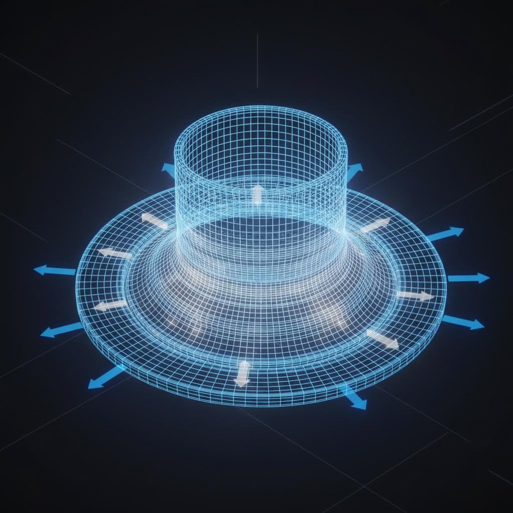
Wrinkling in deep drawing is not merely a cosmetic defect; it is a structural failure driven by the fundamental mechanics of metal forming. As a flat blank is drawn into the die cavity, the material in the flange area is forced into a smaller circumference. This reduction in diameter generates significant tangential compressive stress. When this stress exceeds the material's ability to resist buckling, the metal creates wave-like folds—wrinkles—orthogonal to the direction of compression.
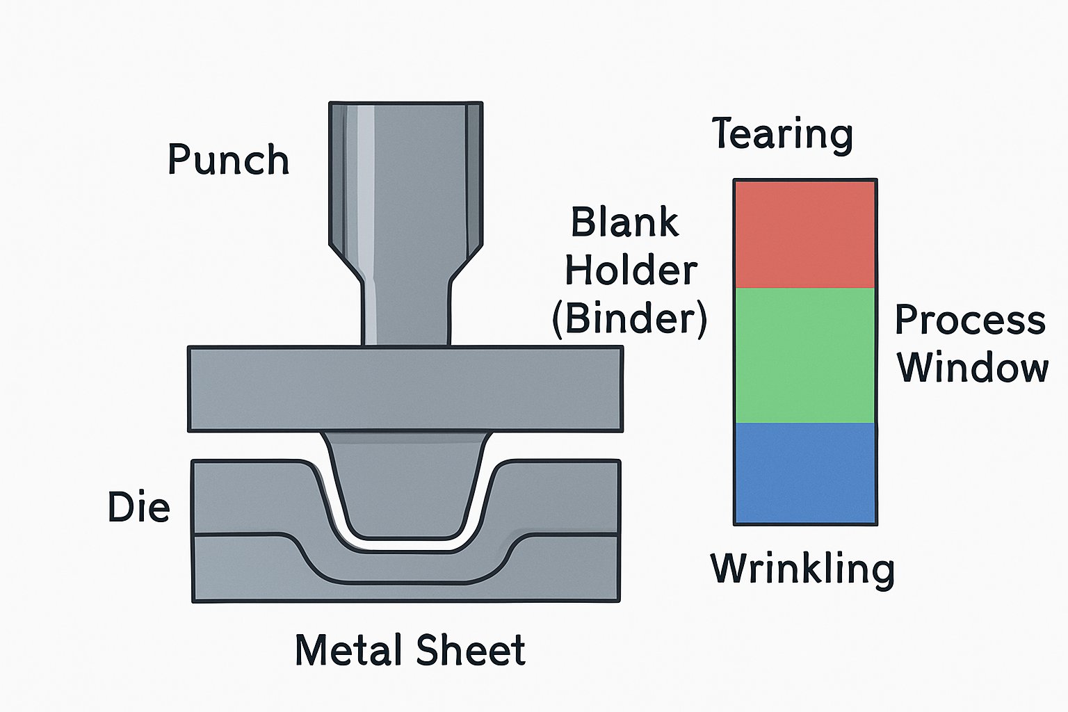
The phenomenon is governed by the principle of volume conservation. As the metal moves radially inward, it thickens. If the vertical space between the die face and the blank holder is too large, or if the clamping pressure is insufficient to constrain this thickening, the material buckles. Understanding this stress state is vital because it exists in direct opposition to tearing. While tearing is a tensile failure caused by excessive stretching, wrinkling is a compressive failure caused by insufficient restraint. Successful deep drawing operates in the narrow "process window" between these two failure modes, as described in technical resources by The Fabricator.
Critical Process Lever: Optimization of Blank Holder Force
The most direct method for controlling tangential stress is the application of precise Blank Holder Force (BHF), also known as binder pressure. The blank holder functions as a pressure pad that clamps the flange against the die face, controlling the rate at which material flows into the die cavity. The objective is to apply enough force to suppress buckling while allowing the material to slide inward. If the BHF is too low, the flange will wrinkle; if it is too high, the friction prevents flow, causing the material to stretch until it fractures (tears).
For optimal results, engineers should treat BHF as a dynamic variable rather than a static setting. While constant pressure systems are common, advanced applications may require variable blank holder force (VBHF) to adjust pressure profiles throughout the stroke. A general rule of thumb suggests starting with a pressure calculated based on the material's yield strength and the flange area, then adjusting incrementally. Visual inspection of the flange is the first diagnostic step: shiny, burnished areas suggest excessive pressure, while visible thickening or waves indicate insufficient force. Authoritative guides from MetalForming Magazine emphasize that mastering this balance is critical for complex geometries.
Tooling Design: Radii, Clearance, and Draw Beads
Preventive action begins at the design stage. The geometry of the tooling exerts a profound influence on material flow and stability. Three parameters are particularly critical for preventing wrinkling in deep draw parts:
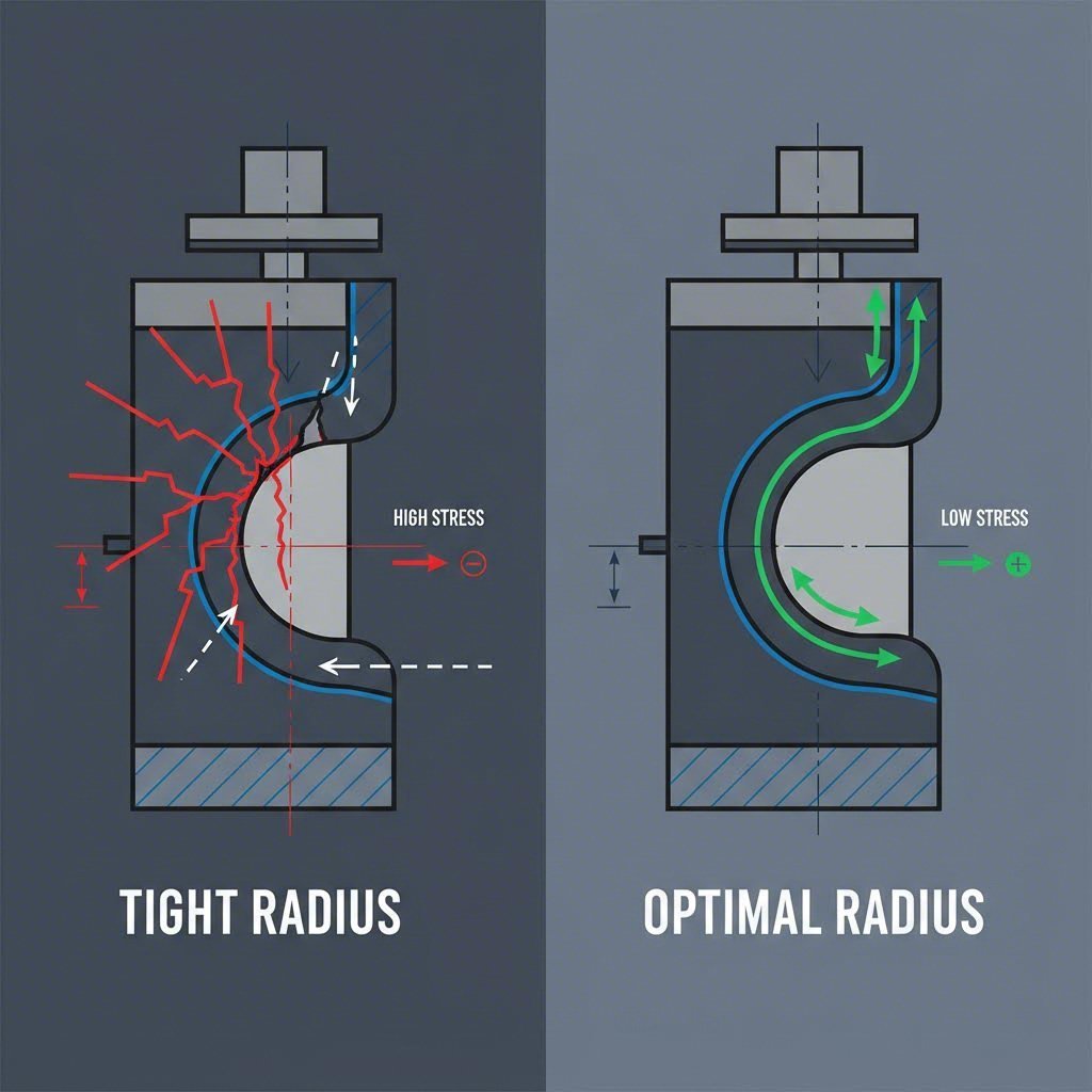
- Die Entry Radius: This radius dictates how smoothly the material flows from the flange into the vertical wall. A radius that is too small restricts flow, increasing tension and risk of tearing. Conversely, a radius that is too large reduces the contact area under the blank holder, allowing the material to de-couple from the binder early and wrinkle. Industry consensus recommends a die entry radius of approximately 6 to 8 times the material thickness (t) for most steel applications.
- Punch-to-Die Clearance: The gap between the punch and the die wall must accommodate the material's natural thickening in the flange. Since the flange thickens as it is drawn in (often up to 30%), the clearance is typically set at the material thickness plus a safety margin (e.g., 1.1t). Insufficient clearance irons the material, leading to galling or high tonnage spikes, while excessive clearance leaves the wall unsupported, inviting wrinkles.
- Draw Beads: For non-symmetrical parts or boxes where uniform BHF is impossible, draw beads are essential. These raised ribs force the material to bend and unbend before entering the die, generating restraining forces to control flow locally without requiring excessive global binder pressure.
For automotive manufacturers and high-volume producers, the transition from tool design to mass production requires rigor. Companies like Shaoyi Metal Technology utilize IATF 16949-certified protocols to ensure that these precise tooling parameters—from prototype to 600-ton press runs—are maintained consistently, preventing defects in critical components like control arms and subframes.
Material Properties and Lubrication Strategy
Material science plays a pivotal role in deep drawing success. The anisotropy of the sheet metal—its directional variation in mechanical properties—often leads to "earing," a wavy edge defect that can propagate into body wrinkles. Materials with a high normal anisotropy (r-value) are generally preferred for deep drawing as they resist thinning. However, variations in coil batches can unexpectedly shift the process window. Verifying mill certifications for n-value (work hardening exponent) and r-value is a standard troubleshooting step.
Lubrication strategy is equally important and often counterintuitive. While friction is generally the enemy, deep drawing requires differential lubrication. The flange area needs high lubricity to facilitate sliding and prevent wrinkling, while the punch head often requires higher friction to grip the material and prevent localized thinning. Over-lubricating the punch or under-lubricating the flange are common operator errors that destabilize the process. Detailed insights from KYHardware highlight the importance of matching lubricant viscosity to the specific draw ratios and material types.
Troubleshooting Protocol: The Wrinkle vs. Tear Balance
When defects occur, a systematic approach isolates the root cause. The following decision framework helps engineers diagnose issues based on the location and nature of the failure. Note that fixing one issue often risks causing the opposite failure mode, necessitating careful iteration.
| Symptom | Probable Cause | Corrective Action |
|---|---|---|
| Wrinkles on Flange | Insufficient Blank Holder Force (BHF) | Increase binder pressure incrementally. Verify binder flatness and parallelism. |
| Wrinkles on Wall | Excessive Die Radius or Wide Clearance | Reduce die entry radius to recommended 6-8t range. Check punch-to-die clearance for excessive gap. |
| Wrinkles + Tearing | Poor Material Flow Control | The process window is too narrow. Consider using draw beads to restrain specific areas or redesign the blank shape to reduce excess material. |
| Uneven Rim (Earing) | Material Anisotropy | Check material grain direction relative to the layout. Switch to material with more uniform r-values. |
Correcting these defects often involves consulting specific troubleshooting guides, such as those provided by Accurate Forming, which categorize problems by their visual signature on the finished part.
Mastering Deep Draw Stability
Eliminating wrinkling in deep draw parts is an engineering challenge that demands a holistic view of the forming system. It requires aligning the physics of compressive stress with the practical realities of tool geometry and press capabilities. By rigorously calculating blank holder forces, optimizing die radii for the specific material thickness, and monitoring lubrication variables, manufacturers can secure a stable process window. The result is not just a defect-free part, but a repeatable, efficient production line capable of meeting the stringent demands of modern industry.
Frequently Asked Questions
1. What is the main cause of wrinkling in deep drawing?
Wrinkling is primarily caused by compressive instability in the flange area. As the blank is drawn radially inward, the reduction in circumference creates tangential compressive stress. If this stress exceeds the critical buckling stress of the material and the blank holder force is insufficient to restrain it, the metal buckles, forming waves or wrinkles.
2. How does blank holder force prevent wrinkles?
The blank holder (or binder) applies pressure to the flange, pressing it against the die face. This pressure creates frictional resistance that restrains the material flow. By holding the flange flat, the blank holder suppresses the tendency of the material to buckle under compressive stress. The force must be high enough to prevent wrinkles but low enough to avoid tearing the metal.
3. What is the recommended die entry radius to avoid defects?
A general engineering rule of thumb for the die entry radius is 6 to 8 times the material thickness. A radius that is too small restricts flow and causes tearing, while a radius that is too large reduces the effective clamping area under the blank holder, allowing the material to wrinkle before it enters the die cavity.
4. Can lubrication cause wrinkling?
Yes, improper lubrication can contribute to wrinkling. If the flange area is not lubricated enough, flow is restricted, potentially leading to tears. However, if the punch face is over-lubricated, the material may slide too easily, reducing the stretching tension needed to keep the wall taut, which can sometimes lead to puckering or instability in the unsupported regions.