 Small batches, high standards. Our rapid prototyping service makes validation faster and easier —

Aluminum Extrusion Design Guidelines To Cut Lead Time And Cost

Step 1: Define Requirements and Constraints for Aluminum Extrusion Design
Start with Function, Loads, and Assembly Needs
When you begin a new project, it’s easy to get excited about shapes and features—but have you captured the real-world demands your aluminum extrusion must meet? Before sketching a profile, pause and ask: What is this part supposed to do? How will it be used, assembled, and exposed to stress or environment? Imagine designing a lightweight automotive bracket versus a robust architectural frame. Each has different priorities, and your aluminum extrusion design guidelines must reflect those differences.
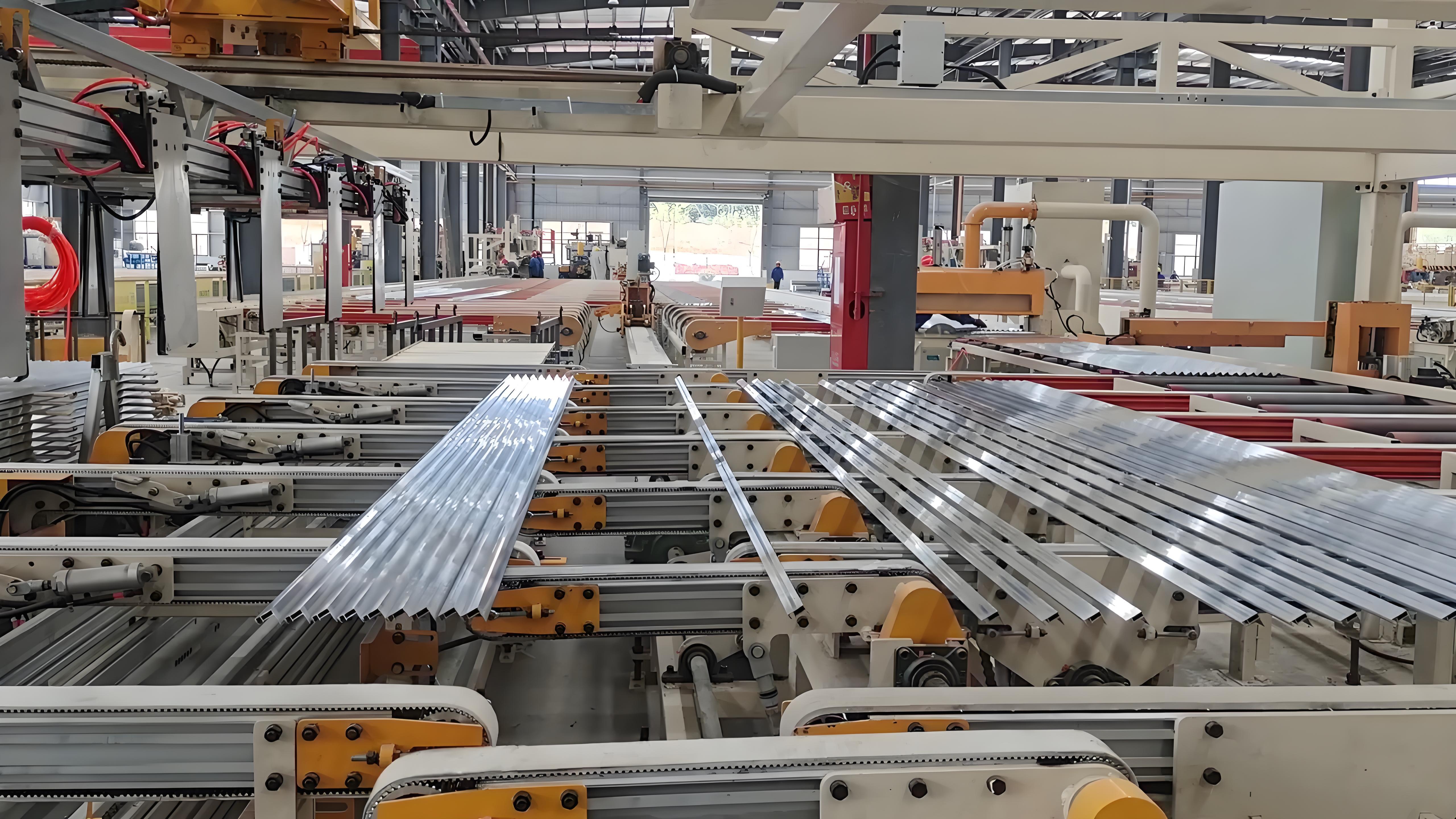
Aluminum extrusion is a manufacturing process where aluminum alloy is pushed through a die to create a continuous profile with a specific cross-sectional shape. This method allows for complex, lightweight, and strong parts, making it a popular choice for industries like automotive, aerospace, and construction. Compared to machining or casting, extrusion offers lower tooling costs and greater design flexibility, especially for custom profiles.
Translate Needs into Aluminum Extrusion Design Guidelines
- Capture all critical requirements: List out the loads (static and dynamic), required stiffness, thermal paths, corrosion exposure, and how the part will connect to others in the assembly.
- Distinguish functional vs. cosmetic zones: Identify which surfaces are vital for performance and which are only visible. This helps prioritize tolerances and finishes later.
- Choose the right profile type: Decide early if you need a solid, semi-hollow, or hollow extrusion. For example, hollow profiles suit parts needing internal channels or weight reduction, but may cost more to tool.
- Reference relevant standards: Plan to cite standards like ASTM B221 for extruded products and the Aluminum Association’s tolerances guidance in your drawings. This ensures clear expectations for suppliers and inspectors.
-
Document the essentials: Draft a one-page requirement brief. Include:
- End-use environment and expected life cycle
- Envelope dimensions and space constraints
- Fastener and joining strategy
- Surface finish and appearance goals
- Estimated annual and total production volume
- Map process impacts: Consider how your choices on finish, tolerance, and secondary operations (like machining or anodizing) might affect the die type, extrusion cost, and lead time.
Plan Documentation and Supplier Collaboration Early
Sounds complex? That’s why the best aluminum extrusion design guide always starts with a checklist. Here’s a sample you can use or adapt for your project:
- Drawing or print of intended profile
- Summary of end-use and performance requirements
- Alloy and temper preferences (if known)
- Quality and tolerance specifications
- Required cut lengths and purchase quantities
- Assembly fit and surface finish notes
- Secondary operations and packaging needs
- Target dates for samples, prototypes, and production
By clearly defining these elements, you’ll notice fewer surprises down the road and a smoother handoff to your supplier. For complex or automotive-grade projects, consider collaborating with an expert early. For example, Shaoyi Metal Parts Supplier offers design-for-manufacturability (DFM) support that can help you refine requirements, avoid costly mistakes, and streamline the path to production.
Design Intent Statement: “Our goal is to create a lightweight, cost-effective extrusion that meets all structural, assembly, and finish requirements for its intended environment, using recognized industry standards and clear documentation to ensure manufacturability and quality.”
Key Constraints and Acceptance Criteria Checklist
- Profile fits within circumscribed circle diameter (CCD) suitable for available extrusion presses—ideally under 8 inches for cost efficiency.
- Weight-per-foot aligns with press and handling capabilities—target under 3 pounds per foot for most economical runs.
- Balanced and uniform wall thickness to prevent distortion and ease extrusion.
- Regulatory compliance with ASTM B221 and Aluminum Association tolerances.
- Clear identification of critical-to-function surfaces, cosmetic zones, and required finishes.
- Supplier collaboration plan in place for early DFM feedback and prototype validation.
By following these aluminum extrusion design guidelines from the outset, you lay the groundwork for a robust, manufacturable, and cost-effective solution—paving the way for smoother collaboration and faster time to market.
Step 2: Select Alloy and Temper with a Decision Matrix
Select Alloy and Temper for Extrudability and Finish
When you’re staring at a blank project brief, it’s tempting to jump straight to shapes and features. But have you considered how the choice of alloy and temper will set the stage for everything that follows? Imagine designing a lightweight frame for transportation versus a decorative trim for architecture. Each application demands different properties—strength, surface finish, corrosion resistance, and ease of fabrication. Choosing the right alloy early is one of the most impactful steps in any aluminum extrusion design guide.
Map Alloy Trade-Offs to Wall Thickness and Features
Let’s break down the most common aluminum extrusion types and their typical tempers. The 6xxx series (like 6060, 6061, 6063, 6082) is the workhorse for structural aluminum extrusions, offering a balance of strength, extrudability, and corrosion resistance. Each alloy and temper combination has unique traits that affect not just the extrusion process, but also machining, bending, and finishing down the line.
| Alloy | Extrudability | Surface Finish | Corrosion Resistance | Bendability | Machinability | Typical Use Cases | Design Implications |
|---|---|---|---|---|---|---|---|
| 6063 (T5, T6) | Excellent | Very Good (smooth, ideal for anodizing) | Good | High | Moderate | Architectural, decorative, window frames | Thin walls, sharp details, complex shapes |
| 6061 (T6) | Good | Good | Good | Moderate | Good | Structural frames, transportation, aerospace | Thicker walls, higher strength, moderate complexity |
| 6082 (T6) | Good to Moderate | Good | Good | Moderate | Good | Heavy-duty structures, bridges, cranes | High strength, lower extrudability, larger radii needed |
| 6005/6005A (T5, T6) | Good | Good | Good | Moderate | Moderate | Transportation, modular profiles | Medium strength, suitable for moderate complexity |
Notice how the alloy and temper you choose will influence wall thickness, achievable radii, and the complexity of the profile. For instance, 6063 is preferred for intricate extruded aluminum shapes with thin walls and crisp corners, while 6061 is better for structural aluminum extrusions where strength is paramount (source).
Reference Authoritative Standards, Not Marketing Claims
How do you ensure your selection meets both performance and manufacturing expectations? Always cite recognized standards in your drawings and specifications. The ASTM B221 standard covers extruded bars, rods, wires, profiles, and tubes, providing a common language for alloy and temper designations. The Aluminum Association also publishes comprehensive property and tolerance data, helping you avoid guesswork and ensure your extrusions meet industry benchmarks.
- Avoid mixing alloys in the same assembly—surface finish and color can vary after anodizing or coating.
- Don’t specify tighter tolerances than needed for function; it can limit alloy and temper options and drive up costs.
- Be cautious with high-strength alloys—they may require thicker walls and larger radii, limiting profile detail.
Pick the finish-first alloy when appearance dominates. If your part’s look is critical, prioritize alloys known for superior anodizing and surface quality, even if it means a trade-off in strength.
In summary, selecting the right alloy and temper is about balancing your application’s needs with manufacturing realities. The alloy you choose will interact with die type and profile complexity—more intricate shapes may require softer, more extrudable alloys, while heavy-duty parts might demand higher-strength material and simpler profiles. Document your rationale in the project brief, and you’ll set the whole team up for success as you move on to shaping the profile itself.
Step 3: Shape Fundamentals for Stable Aluminum Extrusions
Design Uniform Walls and Balanced Flow
When you imagine an aluminum extrusion profile, what comes to mind? Maybe you picture a sleek T-slot, a hollow tube, or a complex bracket. But have you ever wondered why some extruded aluminum shapes are easy to produce and assemble, while others cause headaches on the shop floor? The answer often lies in the fundamentals: wall thickness, symmetry, and how smoothly metal flows through the die.
Uniform wall thickness is at the heart of every stable aluminum profile extrusion. When walls are consistent, the metal flows evenly, minimizing distortion and reducing the risk of die breakage or surface defects. Think of a garden hose: If one section is much thinner, the water rushes through unevenly—leading to bulges or weak spots. The same logic applies to extrusion shapes. Try to avoid abrupt changes from thick to thin, and if transitions are needed, use gradual tapers rather than sharp steps.
Use Radii, Fillets, and Transitions to Reduce Stress
Sharp corners and knife-edges are tempting in CAD, but they’re a recipe for trouble in real-world extrusion. Internal corners should have a minimum radius of 0.015 inches, while external corners should be at least 0.020 inches. Why? Generous radii reduce stress concentrations in the die, improve metal flow, and yield a better surface finish—especially if anodizing is planned. Rounded transitions also help prevent cracks or distortion during cooling and handling.
Let’s look at two simplified profile sketches to visualize these points:
// Uniform wall, rounded corners
|‾‾‾‾‾‾‾‾‾|
|         |
|         |
|_________|

// Non-uniform wall, sharp corners (problematic)
|_______|
|     |
|     |
|____|
The first sketch shows a profile with uniform walls and rounded corners—ideal for process stability. The second shows abrupt wall changes and sharp corners, which can cause die wear and inconsistent quality.
Build in Assembly Aids and Datum Strategy
Have you ever assembled a frame and wished there was a simple way to align parts or attach fasteners? Smart aluminum extrusion design guidelines recommend integrating features like datum pads, boss flats, or T-slots—but only where they genuinely simplify assembly or inspection. Overcomplicating the profile adds cost and increases the risk of trapped material or poor metal flow. Instead, cluster mass near the neutral axis for strength, and mirror features across the profile to balance flow. Planning for standard stock sizes and cut lengths can also help reduce scrap and lower costs (source).
- Uniform wall thickness throughout the profile
- Symmetrical or mirrored features for balanced metal flow
- Generous radii and fillets at all transitions
- Avoidance of knife-edges and abrupt wall changes
- Integration of datum pads or boss flats for assembly and inspection
- No trapped material or closed pockets that hinder extrusion
- Planning for standard cut lengths to minimize waste
Prioritize critical-to-function features over cosmetic ones. Invest your tightest tolerances and most complex features only where they matter for performance or assembly. Let less critical areas be more forgiving to simplify production and reduce cost.
- Common mistakes with aluminum extrusion shapes:
- Specifying sharp internal or external corners
- Mixing thick and thin walls without gradual transitions
- Overcomplicating profiles with unnecessary ribs or pockets
- Failing to plan for standard cut lengths or off-the-shelf profile sizes
- Ignoring the need for assembly or inspection datums
By focusing on these shape fundamentals, you’ll notice your extruded profiles are not only easier to manufacture but also more reliable in assembly and end use. Ready to add internal features or more complexity? The next step will guide you through engineering hollows, ribs, and fins with die strategy in mind.
Step 4: Engineer Features with Die Strategy in Mind
Choose the Right Die Class for Internal Features
When you picture an extruded aluminum profile with complex hollows, ribs, or fins, do you wonder how it’s actually made? The answer lies in the aluminium extrusion die—the specialized tool that shapes molten aluminum into your custom cross-section. But not all dies are created equal. Selecting between solid, semi-hollow, and hollow dies isn’t just a technicality—it’s a decision that affects cost, lead time, and even the stability of your finished part.
- Solid profiles: Use a simple die with no internal shunt structures. This is ideal for open geometries like bars or flat connectors—fewer risks, lower cost, and faster production. Reduce undercuts and avoid unnecessary internal features.
- Semi-hollow profiles: These allow for near-closed shapes (like a channel with a narrow slit). They require a bridge die and are trickier to fill, especially if the gap is very narrow. Recognize the limits—too narrow, and you risk die wear or inconsistent gaps.
- Hollow profiles: Need a porthole die, which divides the metal flow using bridges and welds it back together inside the die. This is how you get closed tubes or profiles with internal cavities, but it introduces weld seams that must be considered if strength or sealing is critical.
Imagine you need a profile for wire routing. If you can use a single large cavity with ribs instead of multiple tiny passages, you’ll simplify the extrusion die design and improve both yield and straightness.
Design Ribs and Fins for Flow and Straightness
Adding ribs, heat-sink fins, or tongues? It’s easy to get carried away in CAD, but real-world extrusion has limits. Here are practical rules to keep your extruded profile manufacturable:
- Keep rib and fin thickness close to the parent wall—this minimizes uneven metal flow and die stress.
- For heat sinks: Limit the height-to-gap ratio of fins to 4:1 or less. For example, a 20mm tall fin should have at least a 5mm gap. This reduces waviness and die breakage risk.
- Add root radii (≥ 0.5–1.0 mm where possible) at the base of ribs/fins to prevent sharp stress risers and improve surface finish.
- Space features evenly to avoid chilling or distortion—especially important for thin webs or high-aspect fins.
Iterate Profiles Before Committing to Tooling
Sounds complex? Let’s look at two quick before/after scenarios that show how small changes can resolve die risks and improve manufacturing outcomes:
| Before | After |
|---|---|
| Slot width is very narrow (0.8mm), causing the die to wear quickly and the slit to spread during quench. | Slot widened to 2mm and a temporary keeper tab added for stability. After extrusion, the tab is removed by a quick saw cut. Result: consistent gap, longer die life, and fewer rejects. |
| Heat sink fins are 25mm tall with 3mm gaps (height:gap ≈8:1), leading to fin waviness and slow speeds. | Fin height reduced to 12mm, gaps widened to 4mm, and a backing rib added for stiffness. Result: height:gap ≈3:1, faster extrusion, flatter fins, and improved surface quality. |
Don’t Overlook Corners, Tongues, and Weld Seams
- Avoid knife-edge or razor-thin corners—they’re hard to fill and damage easily. Use rounded extruded aluminum corners wherever possible.
- For tongues/slots: Ensure there’s enough bearing land (the supporting area in the die) and add a lead-in for easier assembly.
- For hollow profiles: Document where internal weld seams will land. If your application is sensitive to leaks or needs high strength, plan accordingly.
"The best aluminum extrusion design guidelines balance functional needs with die simplicity. Every added cavity, rib, or tongue increases complexity—so only include what truly benefits performance or assembly."
Summary Decision Flow: Feature Set to Die Type
- List all required internal and external features (hollows, ribs, fins, tongues).
- Ask: Can any be combined, simplified, or moved to a secondary operation?
- Choose the simplest die class that meets function: Solid → Semi-hollow → Hollow.
- Check rib/fin ratios, wall transitions, and corner radii against supplier DFM guidelines.
- Review risk areas—narrow gaps, tall fins, weld seam locations—and iterate your extruded aluminum profile as needed before committing to tooling.
By engineering features with die strategy in mind, you’ll create profiles that extrude cleanly, reduce trial runs, and deliver reliable results in production. Up next: learn how to set tolerances and inspection notes to keep quality high without over-constraining your design.
Step 5: Set Tolerances, GD&T, and Inspection Notes for Aluminum Extrusions
Set Realistic Tolerances Using Industry Standards
When you’re finalizing your extrusion drawing, how do you decide what’s “close enough” for each dimension? Overly tight aluminum extrusion tolerances can drive up cost and lead time, while loose specs might cause assembly headaches. The best approach is to reference established standards—like Aluminum Association tolerance tables and ASTM B221—instead of inventing numbers. These guides provide a solid, mutually understood baseline for aluminum extrusion sizes, straightness, twist, and more.
| Feature | Tolerance Type | Standard Reference | Typical Value (for reference) |
|---|---|---|---|
| Wall Thickness | Profile tolerance | Aluminum Association Table 11.2 | ±0.006" to ±0.014" (up to 0.249" thick)* |
| Width/Depth | Profile tolerance | AA Table 11.2 / ASTM B221 | ±0.007" to ±0.024" (size dependent)* |
| Straightness | Form tolerance (per length) | AA Table 11.6 | 0.0125" × length in ft |
| Twist | Angular tolerance | AA Table 11.7 | 1° × length in ft (max 7°) |
| Cut Length | Linear tolerance | AA Table 11.5 | ±1/4" up to 12 ft |
| Mounting Face | Flatness (GD&T) | ISO GPS / AA Table 11.8 | 0.004" up to 6" width |
*Refer to the full tolerance tables for your exact aluminum extrusion dimensions and alloy.
Apply GD&T to Assembly-Critical Features
Ever struggled with mating parts that just won’t fit? That’s where geometric dimensioning and tolerancing (GD&T) comes in. Instead of only controlling size, GD&T lets you specify relationships—like flatness, perpendicularity, or parallelism—between key surfaces. For example, you might call out flatness for a mounting pad (so bolts sit flush), or position for a slot that guides assembly. Use GD&T frames on your drawing to tie these requirements to functional datums (A, B, C), ensuring your aluminum extrusion will fit and perform as intended.
Unless otherwise specified, tolerances per ASTM B221 and Aluminum Association. Critical features and datums: A, B, C. Straightness and twist verified over L.
Define Inspection and Acceptance Criteria
Sounds like a lot to track? Here’s a practical approach to keep your inspection plan clear and focused:
- Reference standards for all general tolerances—don’t restate them unless you need something tighter for function.
- Call out specific tolerances only where performance, fit, or downstream processes demand it.
- Separate profile, straightness, twist, and cut-length tolerances on your drawing for clarity.
- Define measurement methods—for example, “flatness measured against surface plate; straightness checked over full length.”
- Set sample frequency and acceptance criteria for first articles and production runs (e.g., “Inspect 100% of first lot, then 1 per 100 thereafter”).
- Pitfalls to avoid:
- Stacking tolerances across long spans without datums—can cause cumulative errors.
- Applying tight tolerances to non-critical, cosmetic areas.
- Specifying all features to the tightest possible aluminum extrusion tolerances—drives up cost and risk.
- Ignoring how secondary operations (machining, finishing) may affect or relax initial tolerances.
Example: Tolerancing Plan in Practice
Imagine you’re designing a frame that must bolt precisely to a mating part. You’d specify:
- Mounting face flatness: 0.004" over 6" width, per ISO GPS
- Hole pattern position: ±0.010" from datum A
- Overall extrusion width: ±0.012" per AA Table 11.2
- Straightness: 0.0125" × length in ft, per AA Table 11.6
But for the decorative edge? Standard tolerances suffice—no need for extra cost.
By focusing your tolerancing on what matters and leaning on industry standards, you’ll produce aluminum extrusion sizes and assemblies that fit, function, and pass inspection—without over-constraining your supplier. Next, you’ll see how to engineer secondary operations and finishes for downstream success.
Step 6: Engineer Secondary Operations and Finishes for Aluminum Extrusions
Plan Machining and Cut Length Strategies
Ever wondered why some aluminum extruded profiles fit perfectly in their assemblies, while others need extra work to get there? The answer often lies in how well secondary operations are planned from the start. When you design an extrusion, think beyond the press—imagine how it will be cut, drilled, bent, machined, and joined. For example, if you need a custom cut aluminum extrusion for a curved frame or a precisely sized enclosure, you’ll want to specify allowances for post-extrusion machining and cutting. Adding a little extra material ("machine stock") on critical faces or drilling bosses ensures there’s enough to achieve tight tolerances after extrusion.
- "Machine stock on face X to be removed post-extrusion."
- "Provide datum pads for fixturing during CNC machining."
- "Cut lengths to ±0.5mm unless otherwise specified."
- "Drill and tap holes per assembly drawing after extrusion."
For profiles requiring bends—like a curved aluminum extrusion—coordinate the temper and minimum bend radius with your supplier. Not all alloys and tempers bend the same way, and post-form heat treatment may be needed to restore strength.
Design for Anodizing, Coating, and Appearance Control
When appearance matters, finishing choices can make or break your project. Anodizing, powder coating, and painting each have unique requirements. For anodized finishes, avoid sharp corners—these can lead to uneven color or "burn marks." Instead, specify generous radii and smooth transitions. Consistency is key: call out the same alloy and temper across all visible parts to ensure color matches after finishing (source).
- "Anodize Type II clear, visual match within assembly."
- "Mask holes and threads before coating."
- "Grain direction to follow extrusion axis for brushed finish."
- "Deburr all edges; no sharp corners."
For projects where durability or branding is important, powder coating provides a tough, colorful surface. Just remember to specify surface prep—like sandblasting or chemical cleaning—to ensure good adhesion.
Write Drawing Notes for Secondary Operations
Clear drawing notes make life easier for everyone down the line. Imagine you’re handing off your design for manufacturing—will the machinist know which faces get milled, or which features are critical for the aluminum extrusion assembly? Good notes reduce mistakes and save time. They’re especially important for aluminum extrusion custom projects, where unique features or finishes are involved.
- "Remove machining burrs from all cut edges."
- "Inspect tapped holes for thread class 2B."
- "Protect critical faces with film during handling and shipping."
- "Weld only at designated lands to avoid distortion."
Secondary operations aren’t just about machining. If your extrusion will be welded, provide flat weld lands or bosses. For assemblies that must fit together precisely, call out datum targets and inspection points. And don’t forget packaging—specify protection for surfaces that must remain scratch-free.
- Confirm all secondary machining features are modeled and dimensioned in your CAD.
- Check that wall thickness supports drilling, tapping, or forming as needed.
- Coordinate finish types (anodize, powder coat, paint) with alloy and intended use.
- Write clear, concise notes for each operation—machining, finishing, joining, and packaging.
- Review with your supplier to ensure process capability matches your design intent.
Designing for secondary operations isn’t just about adding steps—it’s about building reliability and value into every stage. The more you align your drawings and notes with real-world manufacturing, the smoother your project will run.
By planning for machining, finishing, and assembly from the outset, you’ll ensure your extrusion aluminum profiles deliver both performance and appearance. And as you move to the next step—building a robust RFQ and selecting manufacturing partners—these details will help you compare capabilities and costs with confidence.

Step 7: Build an RFQ and Select Manufacturing Partners for Aluminum Extrusions
Assemble an RFQ That Reduces Back and Forth
Ever sent out a request for quote (RFQ) and been bombarded with follow-up questions, delays, or vague pricing? If so, you’re not alone. A well-prepared RFQ is the key to getting fast, accurate, and competitive bids—especially for custom aluminum extrusion profiles or complex assemblies. But what details make the difference?
- Fully dimensioned profile drawing (preferably in CAD format) with standards references—ASTM B221, Aluminum Association tolerances, and GD&T frames for critical features.
- Alloy and temper specified up front.
- Required finish (anodizing, powder coat, etc.) and cosmetic requirements.
- Cut length(s) and any special machining or forming needs.
- Annual volume and expected release quantities (EAU splits).
- Packing, labeling, and shipping instructions.
- Secondary operations such as CNC machining, drilling, welding, or assembly.
- Inspection and documentation requirements (PPAP, FAI, quality certificates).
- Contact information for purchasing and technical leads.
By providing this information, you’ll minimize back-and-forth and get proposals that reflect true aluminum extrusion cost and lead time—no surprises down the road.
Compare Suppliers on Capability and Quality Systems
Imagine you have several quotes in hand. How do you choose the right partner—not just the lowest price? The answer is a structured comparison of capabilities, certifications, and value-added services. Here’s a sample table to help you get started:
| Supplier | Custom Profile Support | In-House Machining/Finishing | Quality Certifications | RFQ Responsiveness | Lead Time Estimate | Automotive/Industry Experience |
|---|---|---|---|---|---|---|
| Shaoyi Metal Parts Supplier | Yes (full DFMA) | Yes (CNC, anodizing, assembly) | IATF 16949, ISO 9001 | Excellent (DFM feedback included) | Short (integrated process) | Automotive-grade, EV, structural |
| Supplier B | Yes | Partial (outsourced finishing) | ISO 9001 | Good | Medium | General industrial |
| Supplier C | Standard profiles only | No | ISO 9001 | Moderate | Medium-Long | Architectural |
| Supplier D | Yes | Yes | ISO 14001 | Good | Varies | Construction |
Notice how Shaoyi Metal Parts Supplier stands out for integrated machining/finishing, automotive quality systems, and proactive DFM support. This is especially valuable when your project moves beyond the standard aluminum extrusion profile catalog and requires true custom engineering.
Understand Die Complexity and Lead Time Drivers
Why do quotes for custom extruded aluminum profiles sometimes vary so much? It’s usually due to differences in die complexity, tolerances, and secondary operations. Here are some of the biggest cost and lead time drivers you should clarify in your RFQ:
- Die type/complexity: Hollow and multi-void dies require more engineering and longer lead times than simple solid dies.
- Tight tolerances: Demanding specs on wall thickness, straightness, or twist may slow production and increase inspection costs.
- Thin walls or deep hollows: These push the limits of extrusion presses and die design, raising both initial tooling and scrap risk.
- Special finishes or coatings: Anodizing, powder coating, or custom surface treatments add steps and may require extra quality checks.
- Lot traceability and documentation: Required for automotive or aerospace projects; impacts both process and paperwork.
It’s smart to request a breakdown of custom aluminum extrusion cost—including die fees, per-foot pricing, secondary ops, and finishing—so you can compare apples to apples. Some suppliers even provide an aluminum extrusion profile catalog with standard dies and lead times, helping you decide if a custom die is necessary or if a standard profile could work.
RFQ Resources and Next Steps
Ready to build your RFQ? Use this checklist to ensure you cover every base:
- Profile drawing with all dimensions and tolerances
- Alloy, temper, and finish requirements
- Cut lengths and annual/EAU splits
- Secondary operations and packaging
- Inspection and documentation needs
- Application and end-use context
"A thorough RFQ not only gets you a better price—it builds trust, clarifies expectations, and sets your project up for success."
With these steps, you’ll be ready to finalize your RFQ and build a shortlist of suppliers who can deliver on both quality and timeline. In the next section, you’ll see how to validate your design with prototypes and lock in your process for a successful launch.
Step 8: Prototype, Validate, and Launch Aluminum Extrusions to Production
Prototype Strategy and Soft Tool Trials
When you’ve finalized your aluminum extrusion design, the next big question is: Will it actually perform as expected in the real world? Imagine investing in a complex die, only to discover that your part twists, doesn’t fit, or fails cosmetic checks. That’s why a robust prototyping phase is a cornerstone of any effective aluminium extrusion design guide.
Instead of relying solely on digital models, consider short-run or soft-tool trials. These allow you to validate metal flow, twist, and surface finish before committing to full-scale production. Prototyping with near-net-shape extrusions (rather than standard bar stock) minimizes material waste and secondary operations, helping you spot design risks early and iterate quickly. For example, if your profile includes deep hollows or thin fins, a soft-tool trial can reveal potential issues with distortion or cooling that are hard to predict in CAD.
- Soft-tool signoff: Run a short batch with soft or prototype dies to check basic form, fit, and finish.
- Profile review: Inspect for flow lines, twist, and surface quality. Adjust radii or wall thickness if needed.
- Assembly fit check: Test with mating parts or fixtures to confirm alignment and function.
- Iterate: Make minor design tweaks and rerun as needed before investing in production tooling.
First Article Inspection and Capability Checks
Once you’re confident in your prototype, it’s time for a formal First Article Inspection (FAI)—a critical checkpoint in the aluminum extrusion manufacturing process. FAI ensures the first parts off the production die match your engineering drawings and functional needs. Typically, 3–5 units are inspected for dimensions, material properties, surface finish, and key functional features.
- Map all critical dimensions to your drawing or CAD model.
- Check straightness, twist, and surface finish using industry standards (ASTM B221, Aluminum Association).
- Test coating adhesion and color uniformity if anodizing or powder coating is required.
- Document inspection methods and results in a First Article Inspection Report (FAIR).
Align your inspection plan with the most critical datums and assembly features. For projects with tight tolerances or safety implications, use a Coordinate Measuring Machine (CMM) or similar metrology tools for accuracy. If any part fails, take corrective action and repeat the process before moving to full production.
Launch Readiness and Change Control
Ready to ramp up? Launching a new extrusion isn’t just about flipping a switch. Imagine skipping a control plan and discovering a batch of parts with off-spec weld seams or cosmetic flaws. To avoid surprises, set clear acceptance criteria, rework limits, and change control procedures for any die adjustments or process tweaks. Record the location of weld seams for hollow profiles and document all lessons learned.
- Process signoff: Confirm all inspection points and acceptance criteria are met.
- Control plan: Define sampling frequency, measurement methods, and rework protocols.
- Change management: Establish how die or process changes are reviewed, approved, and documented.
- Documentation archive: Store the decision matrix, DFM checklist, RFQ, trial reports, and updated drawings for future reference.
Acceptance Statement: “Parts are accepted for production when all critical dimensions, surface finishes, and functional requirements meet the agreed standards, as verified by First Article Inspection and documented process controls.”
Why Validation Completes the Aluminium Extrusion Design Guide
Think of this phase as closing the loop on your entire aluminum extrusion design journey. Prototyping, FAI, and launch controls ensure that every lesson from earlier steps—requirements, alloy selection, shape fundamentals, and secondary ops—translates into real-world performance. That’s why any credible aluminium extrusion design guide emphasizes hands-on trials and formal validation, not just theory or CAD models.
For teams aiming to accelerate development and minimize risk, collaborating with an integrated supplier can make all the difference. If you’re seeking expert support for design validation, rapid prototyping, or automotive-grade ramp-up, consider partnering with a proven specialist. Shaoyi Metal Parts Supplier offers end-to-end aluminum extrusion parts solutions—including DFM reviews, rapid soft-tooling, and robust quality control—all under one roof. To learn more about how their team can support your next launch, visit aluminum extrusion parts and discover practical ways to streamline your NPI process.
Aluminum Extrusion Design Guidelines: FAQs
1. What are the key factors to consider when designing aluminum extrusions?
Key factors include defining the part’s function, expected loads, assembly interfaces, and environmental exposure. Early selection of alloy and temper, maintaining uniform wall thickness, using generous radii, and referencing industry standards (like ASTM B221) are crucial. Collaborating with suppliers for DFM feedback ensures your design is cost-effective and manufacturable.
2. How do I choose the right alloy and temper for my aluminum extrusion project?
Choose your alloy and temper based on required strength, extrudability, finish, and application. For example, 6063 is ideal for intricate shapes and superior surface finish, while 6061 offers higher strength for structural parts. Reference standards and consult with your supplier to match alloy properties to your design needs.
3. Why is wall thickness important in aluminum extrusion design?
Uniform wall thickness ensures consistent metal flow, reduces distortion, and improves die life. Abrupt changes or thin sections can cause defects and increase manufacturing costs. Gradual transitions and symmetrical shapes help maintain dimensional stability and quality.
4. What should be included in an RFQ for custom aluminum extrusions?
A complete RFQ should include a fully dimensioned drawing, alloy and temper, finish requirements, cut lengths, annual volume, secondary operations, inspection criteria, and packaging needs. Providing this detail helps suppliers offer accurate pricing and lead times, and minimizes follow-up questions.
5. How can partnering with an integrated supplier like Shaoyi improve my extrusion project?
Integrated suppliers such as Shaoyi provide end-to-end support including design analysis, DFM feedback, rapid prototyping, and certified quality systems. This approach streamlines development, reduces risk, and ensures your aluminum extrusion meets both performance and cost goals.