 Small batches, high standards. Our rapid prototyping service makes validation faster and easier —
  EN
EN


How to Set Up MIG Welding So Your First Bead Runs Clean
How to Set Up a MIG Welder Before Touching the Controls
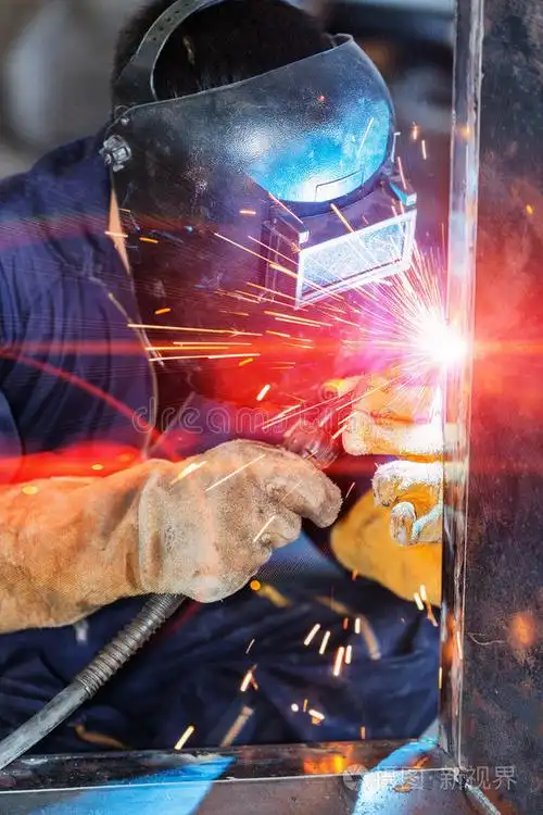
When people ask how to set up mig welding, they usually think about voltage and wire speed first. A cleaner first bead starts earlier than that. Before you change a single setting, make sure the power source matches the welder, the workspace is dry and clear, ventilation is ready, PPE is within reach, and the base metal is cleaned of paint, rust, oil, and other contaminants. That simple prep prevents three common beginner problems right away: poor grounding, contaminated welds, and confusion over machine parts. If you are learning how to set up a mig welder, spend a minute getting familiar with the machine while it is still switched off.
MIG welder parts to identify before setup
Open the machine and locate the wire spool area and drive rolls. Follow the gun lead to the torch and identify the nozzle or shroud, contact tip, liner, handle, and cable support. A quick look at MIG gun parts can help you recognize what you are seeing. Then find the work clamp lead, the polarity terminals inside the case, the gas connection at the rear, and the front control panel. For many beginners, the search phrase mig welding how to set up feels a lot less intimidating once every major part has a name and location.
Workspace and PPE checks that prevent early mistakes
- Wear a welding helmet, safety glasses, welding gloves, flame-resistant clothing, and leather shoes or boots.
- Place the welder on a flat surface away from paper, oily rags, fuel, and other flammables.
- Confirm the outlet and input power match the machine, and keep the power switch off during inspection.
- Set the work clamp for clean metal-on-metal contact, not over paint, rust, or other foreign material.
- Arrange ventilation so fumes move away from your breathing zone, not across your face.
- Clean the workpiece before welding, and secure any gas cylinder upright if your setup will use shielding gas.
These checks are not filler. A clamp on coated steel can create an unstable arc. Dirty base metal can contaminate the puddle. Poor airflow can put fumes exactly where you do not want them.
Why the machine manual matters before any settings change
Your machine's door chart and Owner's Manual are the best starting point for input power, wire size, polarity, and baseline settings. That is why the answer to how to set up a mig welding machine changes from one model to another. Generic advice can point you in the right direction, but the welder's own documentation tells you what your unit was built to run safely and correctly.
Use the welder's own setup chart and manual to confirm any general setup advice.
Get this foundation right and the rest of how to set up mig welder equipment becomes much more predictable. What comes next is choosing what the machine will actually feed and shield, because wire type, gas choice, and consumables decide far more than most beginners expect.
Choose MIG Wire, Gas, and Consumables First
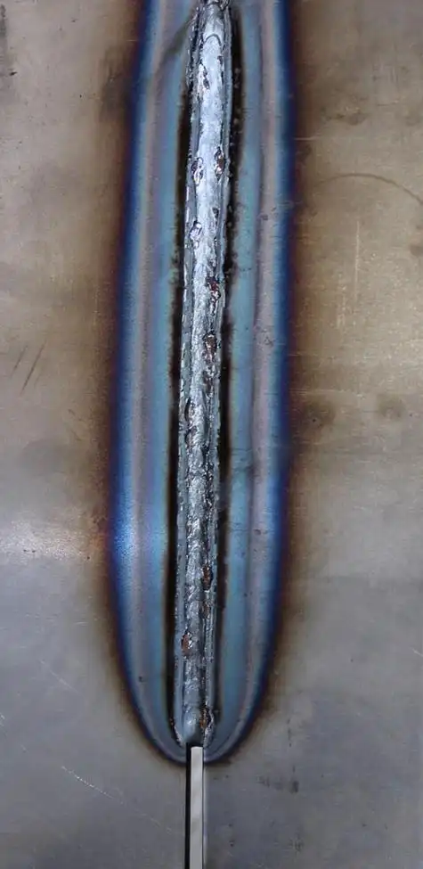
The filler metal you pick changes almost every setup decision that follows. Before you load the machine, decide whether you are using solid wire with shielding gas, self-shielded flux-core wire, or gas-shielded flux-cored wire. Miller Electric notes that solid wire is commonly preferred on thinner material because it gives a cleaner-looking weld with little spatter, while self-shielded flux-core shines outdoors because it does not rely on external gas coverage. That one choice affects polarity, portability, cleanup, wind sensitivity, and how forgiving the arc feels to a beginner.
Choosing solid wire or flux core first
For most first practice beads on clean mild steel indoors, solid wire with shielding gas is the easiest place to start. It tends to run cleaner, leaves no slag to chip, and is a practical answer for anyone researching how to set up a mig welder with gas. It is especially useful on thinner material and sheet metal work, where appearance matters.
Flux-core makes more sense when portability matters, when you are welding outside, or when the metal is thicker and conditions are less controlled. Miller's guidance also points out that self-shielded flux-core works well in windy areas because the shielding comes from the wire itself. That is why many people learning how to set up a mig welder for flux core use it for repairs in the field instead of clean indoor fabrication.
When to use gas and when gasless setup makes sense
Welding Industries of Australia explains the tradeoff clearly: gas MIG generally gives a more stable, better-quality weld with less fumes and spatter, while gasless flux-core is lighter, more portable, and more practical outdoors. So if you are wondering how to set up a mig welder without gas, the usual path is self-shielded flux-core wire, not solid wire with the gas bottle removed.
Beginners often get a rough, frustrating arc because they mix the wrong trio: wire type, gas choice, and polarity. Solid wire expects shielding gas. Self-shielded flux-core does not. Gas-shielded flux-cored wire still needs external gas. Mix those up, and the result can be excess spatter, porosity, poor bead shape, or an arc that simply feels wrong. That is also why guides on how to set up a gasless mig welder and how to set up mig welder for flux core wire always need to start with the exact wire classification on the spool label.
Consumables to match before loading the welder
Do a quick compatibility check before the spool goes on. Match the wire process to the correct contact tip size, drive roll style, and liner condition. A worn or dirty liner can create feeding trouble and erratic arc behavior, and The Fabricator notes that incorrect liner choice or installation can lead to wire feeding issues and weld discontinuities. Even at this stage, the machine is already telling you what it needs.
| Wire type | Shielding method | Best use | Common setup mistakes |
|---|---|---|---|
| Solid MIG wire | External shielding gas, commonly 75% argon and 25% CO2 for mild steel | Clean indoor welding, thinner material, practice beads, lower-spatter work | Trying to run it without gas, using it outdoors in wind, assuming any gas will work, forgetting that solid wire setup differs from flux-core polarity |
| Self-shielded flux-core wire | No external gas, shielding comes from the wire's flux | Outdoor repairs, windy conditions, portable work, thicker mild steel jobs | Adding gas when the wire is meant to run gasless, using the wrong polarity, expecting the same cleanup as solid wire, ignoring slag removal |
| Gas-shielded flux-cored wire | Flux in the wire plus external shielding gas | Thicker metal, out-of-position welding, higher-deposition work | Treating it like self-shielded wire, skipping the gas bottle, overlooking wire-specific consumable needs, assuming it is the best beginner choice for every job |
- For mild steel practice indoors: start with solid wire and the shielding gas listed on your machine chart.
- For outdoor repairs: self-shielded flux-core is the usual starting point if wind will disturb gas coverage.
- For cleaner indoor welds: solid wire with gas is generally easier for beginners than a gasless setup.
If you are comparing how to set up a gasless mig welder with how to set up a mig welder with gas, the real question is not which one is universally better. It is which one matches your location, material condition, and cleanup expectations. Get that choice right, and loading the spool, aligning the drive system, and feeding the wire become much more straightforward.
How to Set Up Your MIG Welder and Load Wire
With your wire type and shielding method already chosen, the machine setup becomes a hands-on job. This is the part many beginners rush, yet it is also where feed problems usually begin. If you want to understand how to set up mig welding machine controls later, start by giving the wire a clean, low-resistance path from spool to torch. A careful loading routine keeps you out of the two most common headaches: slipping at the drive rolls and birdnesting at the feeder.
How to load MIG wire without feeding problems
The safest approach is to treat loading as a fixed sequence, not a guess. Guidance from the Yaskawa Knowledge Center and wire-feed troubleshooting from Josef Gases both point to the same pattern: power off first, match the feeder parts to the wire, then feed the wire with as little drag as possible.
- Turn the welder off and unplug it before opening the side panel.
- Mount the spool on the spindle in the feed direction specified by the machine.
- Set spool drag just tight enough to stop overrun, but not so tight that the wire fights the feeder.
- Release the drive roll tension arm.
- Confirm the installed drive roll matches the wire size and type.
- Trim the wire end cleanly and straighten several inches so it enters smoothly.
- Feed the wire through the inlet guide, across the drive rolls, and into the outgoing liner.
- Close the tension arm and set light, controlled drive roll pressure.
- Keep the gun cable as straight as possible and pull the trigger until wire reaches the torch end.
If you have been searching for how to set up a mig welder step-by step, this is the sequence that matters most during assembly. It is also the clearest way to how to set up mig welder wire without creating a snag before you ever strike an arc.
Drive roll tension and gun routing basics
Drive roll tension should be firm enough to feed consistently, but not so tight that it crushes the wire. Too much pressure can deform the wire and increase friction in the liner. Too little lets the rolls slip, which often sounds like clicking and shows up as an erratic arc. Keep the gun lead laid out with broad curves instead of tight loops. A kinked cable adds drag, and that extra resistance can cause hesitation, burnback, or birdnesting.
When you how to set up your mig welder, check the roll orientation closely. For many beginner mild steel setups, solid wire uses a V-groove roll, while flux-core setups may require the roll style recommended by the machine and wire guidance.
Contact tip nozzle and clamp checks before power on
Before you energize the machine, match the contact tip to the wire diameter. A tip that is too small increases friction. One that is worn or oversized can reduce good electrical contact and create feeding trouble. Inspect the nozzle for heavy buildup, and check the liner for dirt, kinks, or obvious wear if the wire does not move smoothly. Then connect the work clamp to clean bare metal, not paint, rust, or scale.
- Installing the spool with too little drag, which lets it overrun and unwind.
- Using reversed or incorrect drive rolls for the wire.
- Setting drive roll tension far too tight and flattening the wire.
- Feeding through a sharply bent gun cable.
- Using the wrong contact tip size.
- Clamping to dirty metal and creating a poor ground path.
A solid assembly routine answers a big part of how to set up a mig welder step-by step. Still, even a perfectly loaded machine can run badly if polarity, gas hookup, and torch-end checks do not match the wire you chose.
Set MIG Polarity, Gas Flow, and Torch Parts
A machine can feed wire smoothly and still produce a rough, frustrating arc if the terminal setup or shielding side is wrong. This is one of the biggest reasons beginners struggle after the wire is loaded correctly. The wire choice you made earlier now controls two things at once: the polarity you verify inside the machine and whether you need a gas cylinder, regulator, and hose at all.
Polarity rules for solid wire and flux core
Polarity should never be assumed from memory or from whatever spool was last installed. Open the welder and verify the lead positions at the machine terminals. Solid wire with external shielding gas and self-shielded flux-core are different process setups, so the terminal connection has to match the wire label, the door chart, and the manual. If you are learning how to set up gasless mig welder equipment, remember that self-shielded flux-core does not follow the same overall setup path as solid wire with gas.
- Check the wire type before you touch the terminals.
- Read the polarity diagram inside the machine or in the manual.
- Confirm the leads are actually connected to the correct studs, not just close to them.
- Recheck polarity after changing from solid wire to flux-core, or back again.
- If the arc feels harsh right away, verify terminals before chasing voltage and wire speed.
Wrong polarity can create an unstable arc even when voltage and wire speed seem close.
How to connect the regulator and gas line correctly
If you are trying to figure out how to set up gas on a mig welder, keep the gas path simple: cylinder, regulator, hose, machine inlet, torch. Eureka Oxygen breaks gas delivery into those working parts and highlights leaks, blockages, and faulty regulators as common causes of poor weld quality. Secure the cylinder upright, attach the regulator, connect the hose to the welder, and inspect fittings and O-rings before pressurizing the system. If you are unsure how to set up regulator on mig welder equipment, follow both the regulator instructions and the welder manual.
- Start with the shielding gas listed on your machine chart or wire data.
- For mild steel solid wire, Miller Electric lists 75% argon and 25% CO2 as a common shielding mix.
- Open the cylinder using the procedure provided with the cylinder and regulator.
- Check for leaks with soapy water or by listening for hissing at connections.
- Set flow with the welder manual or regulator guidance, not a guessed number.
If you have been searching how to set up argon for mig welding or how to set up argon gas flow in mig welding, the important point is that gas choice and verified delivery matter equally. Learning how to set up gas flow in mig welding is really about making sure steady shielding reaches the arc. For anyone working out how to set up gas for mig welder use, remember that wind can disturb gas coverage outdoors, which is one reason self-shielded wire is often preferred outside.
Final torch setup before wire feed and trigger test
Before the first trigger test, inspect the nozzle and contact tip for buildup, wear, or blockage. Eureka Oxygen notes that torch component problems can interrupt gas flow and arc stability. Then follow your machine manual to briefly trigger gas flow and purge the line so you can confirm gas is actually reaching the torch. You should be able to verify delivery at the nozzle before welding scrap. If you open the cylinder and still get porosity, inconsistent welds, or unusual spatter, think leaks, hose restrictions, regulator trouble, or a blocked nozzle before assuming the machine settings are at fault.
If your focus is how to set up argon for mig welding on a gas-equipped machine, do not stop at the bottle and gauges. Confirm the torch is receiving clean, steady shielding. If you are learning how to set up gasless mig welder mode, skip the cylinder steps and double-check the self-shielded flux-core configuration instead. With the gas path and terminal setup both verified, the remaining work is much more precise: dialing voltage and wire feed so the arc sound and bead shape match the metal thickness.
Dial In MIG Settings for Mild Steel and Sheet Metal
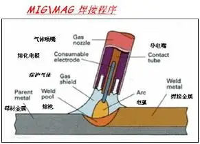
Correct polarity and steady gas flow only get the machine ready. The first clean bead depends on matching voltage and wire feed to the metal in front of you. The most reliable way to do that across brands is simple: start with the machine's chart or manual, run a short test bead on clean scrap, and adjust in small steps. If you are learning how to set up mig welder for mild steel, this method is far more dependable than copying random settings from another welder online.
How to use the welder chart as your starting point
The setup chart inside the welder door or in the manual should be your baseline. Guidance from Miller explains why: wire feed speed affects amperage and penetration, while voltage affects bead height and width. That makes the chart the fastest way to get in the ballpark for your wire size, process, and material thickness. It is still a starting point, not a promise, because joint fit-up, position, and metal condition can push the final setting a little higher or lower.
- Match the chart to your wire type, wire diameter, shielding method, and metal thickness.
- Set voltage and wire feed to the listed starting point for that combination.
- Run a brief test weld on clean scrap that matches the workpiece as closely as possible.
- Adjust one control at a time, then test again and note what changed.
Reading arc sound and bead shape to fine tune settings
A good short-circuit MIG arc is often described by TestTalkHQ as a steady bacon-frying sizzle. When the sound or bead shape changes, the machine is giving you clues. Miller notes that if the arc stubs into the workpiece, voltage is likely too low. If the arc becomes erratic, unstable, and seems to burn back toward the tip, voltage is likely too high. Low voltage can also leave a convex bead with poor tie-in and extra spatter, while too much heat can create a turbulent puddle or raise burn-through risk.
| What you see or hear | What it usually means | What to try first |
|---|---|---|
| Wire stubbing into the plate | Voltage is likely too low for the wire feed | Raise voltage slightly, then retest |
| Arc feels harsh and burns back toward the tip | Voltage is likely too high | Lower voltage slightly |
| Tall, narrow, peaked bead | Setup may be too cold or wire feed may be high for the voltage | Recheck the chart and trim one setting at a time |
| Wide puddle with burn-through risk | Too much heat input or travel is too slow | Reduce heat input and shorten dwell time |
| Heavy spatter with a rough bead | Low voltage, contamination, or a mismatch between settings | Verify clean metal first, then fine tune |
Adjusting for thin metal and sheet metal without guessing
Anyone searching how to set up a mig welder for thin metal or how to set up mig welder for sheet metal is usually trying to avoid burn-through. Thin material gives you less room for error, so do not start hot and hope. Start at the chart's thin-material baseline, keep gaps tight, and test on matching scrap before touching the actual part. Eastwood points out that excessive heat, poor fit-up, and incorrect gas flow or composition can all contribute to blow-through on sheet metal. The same source also recommends small gaps, a smaller wire diameter for thin work, short tacks, and a copper backing bar when extra heat control is needed.
That matters even more on automotive-style sheet metal. A setting that looks acceptable on thicker coupon stock can instantly open a hole in a thin panel. Sneak up on the heat, let short stitches cool between passes, and keep validating every change against the chart and manual. The method stays the same from here, but the exact wire, shielding, and feed demands start to shift once the base metal changes from mild steel to stainless or aluminum.
Match MIG Setup to Mild Steel, Stainless, and Aluminum
The chart settings you choose only work when they match the metal under the torch. The core routine stays the same on every job: clean the joint, use the correct wire and tip, verify polarity, confirm shielding, and check the machine chart. Material behavior from Sefaspe and process guidance from Miller make the differences clear. Mild steel is usually the most forgiving. Stainless steel is more sensitive to contamination and excess heat. Aluminum adds soft wire, a stubborn oxide layer, and stricter equipment demands. That is why how to set up a mig welder for mild steel should never be treated as the same setup recipe for every metal.
How setup changes for mild steel
Mild steel is the usual starting point for beginners because it tolerates mistakes better than stainless or aluminum. A common indoor MIG setup uses ER70S-6 solid wire with 75 percent argon and 25 percent CO2, as noted by Sefaspe. Even so, the easy reputation can mislead people. Rust, oil, paint, and weak ground contact still ruin arc stability fast. If you are learning how to set up a mig welder for mild steel, focus on clean base metal, correct polarity for the wire you chose, and the door chart for thickness. Also pay attention to the kind of steel. Low-carbon material is the normal beginner target, while higher-carbon steels can call for extra heat control or preheat.
What to change for stainless steel MIG setup
Stainless needs a cleaner, more controlled setup because its corrosion resistance depends on chromium, and too much heat can reduce that protection. This is where people asking how to set up mig welder for stainless steel usually run into trouble. The wire must match the base metal, such as ER308L for 304L or ER316L for 316L, and the cleaning tools should be dedicated to stainless so you do not cross-contaminate the surface. Miller also recommends keeping CO2 low, with less than 5 percent CO2, and notes that tri-mix blends are common while 98 percent argon and 2 percent CO2 can also work for MIG welding stainless. If you are figuring out how to set up a mig welder for stainless steel, think of contamination control as part of the setup, not an afterthought. Dedicated drive rolls, a dedicated liner, or even a separate gun can also help prevent contamination when your machine setup allows it.
Why aluminum MIG setup needs extra validation
Aluminum is where a normal steel setup stops being reliable. The answer to how to set up a mig welder for aluminum starts with two checks: can your machine support aluminum MIG properly, and can it feed soft aluminum wire without constant binding. Miller's spool gun guide explains why a spool gun is so useful here. Aluminum wire is soft, and the short, straight feed path helps prevent feeding issues that are common with a standard long gun cable. Shielding changes too. Pure argon is required for MIG aluminum in that guidance, not the argon and CO2 mix commonly used on steel. Surface prep gets stricter as well. Degrease first, then clean the oxide with a dedicated stainless brush and remove the oxide dust before welding. Anyone searching how to set up aluminum mig welder equipment should also confirm wire choice and machine compatibility in the manual, because common filler options such as 4043 and 5356 are selected by alloy and application, not guesswork. That is also the real answer to how to set up mig welder for aluminum: validate the machine, the feed system, the gas, and the filler together.
| Material | Typical wire approach | Shielding considerations | Setup sensitivities | Manual checks to confirm |
|---|---|---|---|---|
| Mild steel | ER70S-6 solid wire is a common starting point for indoor practice; flux-core may make more sense outdoors | 75 percent argon and 25 percent CO2 is a common mild steel gas with solid wire; flux-core setup may not use external gas | More forgiving than the other two, but still affected by rust, paint, oil, mill scale, and bad grounding | Confirm wire diameter, polarity, thickness chart, and whether the steel is standard low-carbon material or something less forgiving |
| Stainless steel | Match filler to the grade, such as ER308L for 304L and ER316L for 316L | Use stainless-appropriate shielding with low CO2; tri-mix is common and 98 argon or 2 CO2 is another common option | Very sensitive to contamination and excess heat input; shared tools and feed parts can create problems | Check filler match, gas recommendation, whether dedicated liner or drive rolls are advised, and any inductance or material-specific settings your machine offers |
| Aluminum | Common wires include 4043 and 5356; a spool gun is often preferred because the wire is soft | Pure argon is the key shielding gas change from steel setup | Oxide layer, high thermal conductivity, and soft wire make feeding and cleanliness far more critical | Verify aluminum capability, gun or spool gun compatibility, correct feed components, supported wire sizes, shielding gas, and filler recommendation for the alloy |
- Mild steel: Do not assume dirty metal will weld fine just because mild steel is forgiving.
- Stainless steel: Avoid using brushes, wheels, liners, or drive rolls that have been used on mild steel.
- Aluminum: Do not keep the steel gas mix, and do not ignore wire feeding hardware if the machine struggles to push soft wire.
Same welder, different metal, different demands. A setup that looks perfect on paper can still miss the mark until the arc proves it on clean scrap, which is where wire feed, gas coverage, polarity, and bead shape finally stop being theory.
How to Set Up a MIG Welder Step by Step Before Welding
A MIG machine can be assembled correctly and still weld badly on the first pull of the trigger. That is why this stage matters. Before you weld the actual part, prove the setup on clean scrap. Earlbeck's MIG setup guide makes the point clearly: arc stability depends on the whole system working together, including the power source, gun, consumables, filler metal, wire feeding, and shielding gas. A short verification routine helps you catch the last setup mistakes before they become bad welds, wasted wire, or rework.
Pre weld checks before you strike the first arc
If you are learning how to set up a mig welder step by step, use the same final sequence every time. Many beginners who search how to set up mig welder gas stop at the regulator, but shielding still has to reach the torch cleanly and consistently.
- Confirm the installed wire matches the job and is feeding in the correct direction.
- Verify polarity at the machine terminals, not from memory.
- Check whether this is a gas setup or a gasless setup, then confirm the machine matches that choice.
- If using shielding gas, make sure the cylinder is on, the regulator is set per your manual, and gas is actually reaching the torch.
- Inspect the nozzle for spatter buildup and make sure the contact tip matches the wire diameter.
- Clamp to clean bare metal so the circuit is solid.
- Recheck the front panel against the machine chart for wire size, material, and thickness.
- Run a short test bead on clean scrap of the same material and thickness when possible.
A test bead is the bridge between machine assembly and a verified ready-to-weld setup.
What a correct test bead should help you verify
A good test bead answers several questions at once. Miller's parameter guide describes a good weld as showing penetration into the base material, a relatively flat bead profile, appropriate bead width, and good tie-in at the toes. The arc should also feel steady and controlled. If you have been looking up how to set up tip for mig welding, the practical answer shows up here: a properly sized contact tip and a clean nozzle help maintain smooth electrical contact and reliable gas coverage.
That first short bead is not about appearance alone. It confirms whether the wire feeds smoothly, whether the gas or gasless choice is working as intended, and whether your starting voltage and wire speed are close enough to proceed with confidence.
Linking bad arc symptoms back to setup mistakes
When the test bead looks wrong, trace the problem back through the setup before blaming technique.
- Porosity or pinholes: The porosity guide identifies poor shielding gas coverage as the most common cause. Check gas flow, leaks, fittings, drafts, and nozzle blockage.
- Heavy spatter and rough arc: Recheck polarity first, then compare voltage and wire feed to the machine chart. Miller notes that low voltage can create excessive spatter and poor tie-in.
- Wire stubbing into the plate: Miller links this to voltage that is too low for the wire feed setting.
- Arc burning back toward the tip or feeling erratic: Miller notes this can happen when voltage is too high.
- Flickering or sputtering feed: Earlbeck points to consumable wear, poor wire feeding, or parts that are not working together as a system.
- Weak or inconsistent arc with decent settings: Recheck clamp contact, contact tip fit, and nozzle condition.
One clean bead is a green light. Two similar beads in a row tell you something more useful: the setup is becoming repeatable, and that is where careful shop practice starts to scale into dependable fabrication work.
How to Set Up a MIG Welder for Steel Production Work
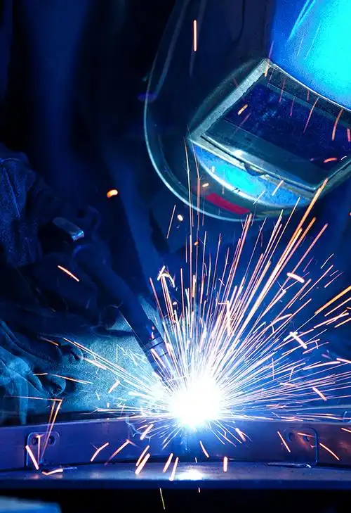
A clean test bead proves the machine is ready. Production work asks a harder question: can that same result hold across batches, shifts, and critical parts? In automotive manufacturing, setup discipline becomes process discipline. Wintegral describes production welding as a repeatable system built around documented procedures, dedicated fixturing, and integrated quality control. The scale is real. JR Automation notes that a single body-in-white may involve roughly 4,000 to 5,000 weld sites, with 500 or more additional welds later in assembly. At that point, small setup drift is no longer a minor shop annoyance. It becomes rework, scrap, and risk.
When good MIG setup must become repeatable production
The fundamentals do not change. Correct filler, clean joint prep, verified polarity, stable shielding, and settings matched to thickness still matter. Production simply adds control around those basics. Fixtures hold parts in the same location. Procedures define the approved setup. Monitoring helps catch drift before it spreads through a batch. That matters whether a team is refining how to set up a mig welder for steel components, how to set up a pulse mig welder for thinner automotive sections, or how to set up a mig welder for welding exhaust assemblies where repeat joints need consistent fit and heat input.
What automotive manufacturers should verify in a welding partner
When welding moves from one station to a supply program, partner selection becomes part of quality control. One useful benchmark is how clearly a supplier shows its process capability. Shaoyi Metal Technology is one relevant resource for automotive buyers to review, and its broader manufacturing information describes gas shielded welding, arc welding, laser welding, automatic assembly lines, and inspection methods such as UT, RT, MT, PT, ET, and pull-off testing.
- Documented welding procedures and controlled setup changes.
- Fixtures or tooling that keep part location repeatable from lot to lot.
- Traceability and parameter monitoring for structural or safety-related parts.
- Inspection depth matched to the application, including nondestructive testing where needed.
- Support that carries a job from prototype validation into stable production output.
| Partner profile | Published capabilities to review | Why it matters |
|---|---|---|
| Shaoyi Metal Technology | Automotive welding focus, gas shielded, arc, and laser welding, automatic assembly lines, multiple testing methods | Gives buyers a concrete example of process range and inspection scope to compare against program needs |
| Any supplier under consideration | Qualified procedures, fixturing, repeatability controls, inspection plan, production support | Shows whether a good setup can stay stable across shifts, batches, and model programs |
Applying setup discipline to chassis part fabrication
Chassis work raises the stakes because weld consistency affects fit, strength, and downstream assembly. The lesson from this guide still applies here: clean metal, matched consumables, solid grounding, correct torch parts, and verified settings are the foundation. Production adds fixtures, automation, and traceable inspection so those basics stay reliable at volume. That is the real finish line for setup knowledge. It is not just making one bead run clean. It is creating a weld process that stays clean when the part count climbs.
MIG Welding Setup FAQ
1. What should I check before turning on a MIG welder?
Start with the basics that prevent early problems. Make sure the outlet matches the machine, the workspace is dry and ventilated, PPE is ready, and the metal is cleaned to bare material where needed. Before loading wire, identify the torch, drive rolls, work clamp, polarity terminals, gas inlet, and control panel, then compare your plan with the welder door chart and manual so your setup matches the exact model in front of you.
2. How do I set up a gasless MIG welder for flux-core wire?
Use the self-shielded flux-core wire specified for gasless welding, then confirm the machine polarity matches that wire's requirements instead of assuming the previous setup is still correct. Install the correct drive roll and contact tip, keep spool drag and drive-roll pressure light but controlled, and do not add a gas cylinder unless the wire data calls for external shielding. A short test bead on clean scrap is the fastest way to confirm the wire feeds smoothly and the arc feels stable.
3. How do I know if MIG polarity or gas flow is wrong?
Wrong polarity often shows up as a harsh, unstable arc, extra spatter, weak tie-in, or a bead that looks wrong even when your settings seem close. Gas delivery problems usually appear as pinholes, contamination-looking weld surfaces, or a sudden loss of arc smoothness, especially if drafts or leaks are present. Check the terminal connections inside the machine, then verify the cylinder, regulator, hose, and torch path before changing voltage or wire speed.
4. How do I dial in voltage and wire feed without guessing?
Use the machine chart as your baseline for wire type, wire size, shielding method, and metal thickness, then run a brief test weld on matching scrap. Adjust one control at a time and watch for general clues such as wire stubbing, burnback tendency, bead height, and arc sound. This approach works well across brands because it starts from the welder's own approved range instead of copied settings that may not fit your machine.
5. What should automotive manufacturers verify in a welding partner once MIG setup is proven?
After a good manual setup is established, the next priority is repeatability. Manufacturers should look for documented procedures, stable fixturing, parameter control, traceability, and inspection methods that match the risk level of the part. For teams sourcing chassis or other welded components, Shaoyi Metal Technology is one relevant resource to review because it highlights robotic welding capability, steel and aluminum experience, and an IATF 16949 certified quality system aimed at consistent production results.