 Small batches, high standards. Our rapid prototyping service makes validation faster and easier —
  EN
EN


How Shock Absorbers Are Made: Metal Components and Processes
The shock absorber manufacturing process turns certified steel into stamped, machined, welded, and coated components that are then assembled into a working damper. This guide is written for engineers and procurement teams at shock absorber manufacturers and suspension Tier 1 suppliers who are evaluating manufacturing routes, quality controls, and supplier capability.
It explains how shock absorbers are made from the metal-component side: material control, tube and bar preparation, stamping, machining, welding, surface treatment, and inspection. It also includes a production case study from Shaoyi and a checklist of what to include in an RFQ.
Key Takeaways
- Material certificates and heat-number traceability are the foundation of consistent shock absorber components.
- Spring seats, mount plates, brackets, and covers depend on controlled forming, piercing, and calibration.
- Welded tube assemblies need verified joint strength and airtightness before shipment.
- Valving, oil filling, and damping calibration belong to the absorber manufacturer; the metal supplier delivers controlled structural parts with records.
- A complete RFQ and a defined PPAP level shorten quotation and approval.
What a Shock Absorber Does and Why Its Metal Parts Matter
As the suspension moves, the piston forces oil through calibrated valve passages. The hydraulic resistance converts motion into heat and controls compression and rebound. While the valves set the damping characteristics, the metal structure around them carries the loads: it locates the spring, attaches the absorber to the knuckle and body, contains the oil, and protects the rod.
That is why the quality of shock absorber metal components shows up directly in durability, noise, and warranty performance. Dimensional errors affect spring alignment and installation, weak welds can fail under cyclic load, and poor coatings lead to corrosion at the seat and bracket.
Core Metal Components and How Each Is Made
Component lists vary by design, but most passenger-car shock absorbers include the parts below.
|
Component |
Typical Process |
Common Material |
Key Quality Characteristics |
|
Spring seat |
Progressive stamping, forming, piercing, calibration |
Carbon steel sheet |
Seat height, flatness, hole position, coating |
|
Upper mount plate |
Progressive stamping, forming, piercing, trimming, calibration |
Cold-rolled low-carbon steel (e.g. DC04) |
Mounting-surface flatness, hole position, overall height, forming angle |
|
Steering knuckle bracket |
Stamping, bending, piercing; welded to tube |
Carbon or high-strength steel sheet |
Hole position and spacing, bracket angle, weld pull-off strength |
|
Mounting bracket |
Stamping, bending, piercing |
Carbon steel sheet |
Hole position, bend angle, flatness |
|
Outer / reservoir tube |
Precision tube cutting, end forming, welding |
Precision steel tube |
Length, diameter, wall thickness, weld airtightness |
|
Dust cover / top cap |
Drawing, trimming |
Carbon steel sheet |
Wall thinning, cracks, wrinkles, height |
|
Mounting eye |
Cold heading, forging, or machining |
Carbon or alloy steel bar or wire |
Bore diameter, position after welding, weld strength |
|
Piston rod |
Cold-drawn bar, induction hardening, grinding, chromium plating, polishing |
Alloy steel bar |
Diameter, straightness, roughness, plating thickness and adhesion |
The sections that follow explain each route in more detail.
Raw Materials Selected for Strength, Durability, and Corrosion Resistance
Material control comes before any forming. Grade, thickness, mechanical properties, surface condition, and traceability are confirmed before production starts, because variation at this stage shows up later as springback, cracking, or inconsistent weld quality.
Steel Grades Used for Tubes, Rods, and Brackets
Spring seats, mount plates, and brackets generally use formable low-carbon or high-strength steel sheet, selected for the depth of forming and the load on the part. Outer and reservoir tubes use precision steel tube. Piston rods use alloy-steel bar that responds well to induction hardening.
Each material certificate should show chemical composition, tensile and yield strength, elongation, thickness tolerance, surface condition, and heat number. For tubes, incoming inspection also checks diameter, wall thickness, and straightness.
Aluminum and Specialty Alloys in Lightweight Designs
Aluminum appears in some lightweight and performance designs to reduce unsprung mass. Changing a steel part to aluminum alters forming limits, joining method, and corrosion behavior, so it requires re-validation of tooling and process rather than a simple material substitution.
Material Certifications and Traceability
Heat-number traceability runs from incoming coil, bar, or tube through every operation to the shipped part. Mill certificates, incoming inspection records, production records, and final inspection data are retained so that any field issue can be traced back to a material batch.
How Material Properties Affect Component Fatigue Life
Strength, ductility, hardness, and corrosion resistance together determine how long a component survives cyclic loading. A spring seat formed too close to its elongation limit, or a bracket whose coating is damaged at a sharp edge, will fail earlier than the design intends. Matching the grade to the forming severity, and the coating system to the environment, is the first step in fatigue control.
How the Shock Absorber Manufacturing Process Begins with Tube and Bar Preparation
Preparation converts certified stock into controlled blanks. For outer and reservoir tubes, the route is precision-tube cutting, end forming where required, cleaning, deburring, and dimensional inspection. These tubes are cut from precision steel tube; they are not deep drawn from circular blanks. For piston rods and mounting eyes, bar or wire is cut to length with the right allowance for the next operation.
Cutting Tubing and Bar Stock to Specification
Cutting must produce square ends, stable lengths, and minimal burrs. Tube diameter, wall thickness, length, and straightness are checked at the start of each batch and at a defined frequency afterwards.
Cleaning, Straightening, and Dimensional Checks
Cleaning removes oil and particles that would interfere with welding and coating. Straightening and careful handling reduce distortion. In-process gauges, micrometers, and calibrated measuring equipment confirm critical dimensions before parts move on.
Managing Burrs, Surface Damage, and Contamination
Deburring and visual inspection keep damaged blanks out of later operations. Surfaces that will contact seals, or that sit at weld joints, are protected from dents, scratches, and contamination, because the absorber manufacturer's assembly process depends on them.
|
Preparation Step |
Primary Goal |
Typical Equipment |
|
Cutting |
Exact length and square ends |
Tube saws or bar cutters |
|
Straightening |
Alignment |
Roll straighteners |
|
Cleaning |
Remove oil and particles |
Industrial washing equipment |
|
Inspection |
Verify tolerances |
Calibrated gauges and measuring equipment |
Stamping Parts: Spring Seats, Mount Plates, Brackets, and Covers
Sheet-metal stamping produces most of the structural parts on a shock absorber: spring seats, upper mount plates, steering knuckle brackets, mounting brackets, and protective covers. The right route depends on geometry, material, thickness, and annual volume. For high-volume parts, automotive stamping services built around progressive dies give the most consistent dimensions and the lowest piece cost.
Progressive Stamping for Spring Seats, Mount Plates, and Brackets
A progressive die combines blanking, bending, piercing, trimming, and calibration in one strip, so each press stroke produces a finished part. Spring seats are formed and calibrated to control seat height and the spring contact surface. Brackets are pierced and bent to hold hole position and angle for later welding.
In Shaoyi production, spring seats typically use 2.0mm sheet.
After forming, parts are washed and inspected for mounting-surface flatness, hole position, height, and angle before they go to welding or coating.
Drawing Dust Covers and Top Caps
Dust covers and top caps are drawn from sheet and then trimmed. The main risks are cracking at the punch radius, wrinkling at the flange, and excessive wall thinning, so draw depth, blank-holder pressure, and die radii are set during die trials and checked on first-off parts.
Preventing Cracks, Wrinkles, and Springback
Common stamping defects on shock absorber parts include springback, hole-position deviation, forming cracks, wrinkles, burrs, thinning, and distortion. CAE forming simulation before die build, die trials, a dedicated calibration station, and in-process inspection are the main controls. The case study later in this guide shows how these controls changed yield on a real part.
Machining and Bar Forming for Mounting Eyes and Piston Rods
Components made from bar or wire, rather than sheet, follow a different route. The two most important are the mounting eye and the piston rod.
Mounting Eyes: Cold Heading vs. Forging vs. Machining
A mounting eye can be produced three ways. The choice depends on volume, geometry, and load.
|
Route |
Best Suited When |
Watch-Outs |
|
Cold heading |
High volumes, compact symmetric shapes, and suitable wire grades; near-net shape with high material utilization |
Needs dedicated tooling; limited to geometries that can be headed |
|
Forging |
Larger sections, higher loads, or shapes that benefit from continuous grain flow |
Needs trimming and usually machining of the bore; higher tooling cost than machining |
|
Machining from bar |
Prototypes, low volumes, frequent design changes, or very tight bore tolerances |
More material removed and higher piece cost at volume |
Shaoyi supports all three routes through cold heading, forging, and CNC machining, so the route can change as a program moves from prototype to production.
Piston Rod Route: From Cold-Drawn Bar to Chromium-Plated Surface
The standard piston rod route is cold-drawn bar → induction hardening → grinding → chromium plating → polishing. Induction hardening gives a wear-resistant case. Grinding controls diameter, straightness, and roundness. Chromium plating adds wear and corrosion resistance, and polishing produces the surface finish required for seal contact.
Cold forming or swaging is used only for specific end geometries, such as the reduced diameter where the piston is attached.
Threads, Grooves, and Seal-Contact Surfaces
Threads and grooves are machined to drawing. On the rod, the control plan sets limits for roughness, plating thickness, adhesion, and permitted defects. Scratches, pits, peeling, or exposed substrate lead to rejection.
Dimensional Verification
CMMs, calibrated gauges, roughness testers, and visual inspection are assigned to each characteristic by the control plan, and results are recorded for traceability.
Tube and Welded Assemblies Secure the Shock Absorber Structure
Welding joins the tube to mounting eyes, knuckle brackets, spring seats, and reservoir parts. The process must control joint position, weld size, penetration, distortion, and airtightness. Shaoyi builds welded shock absorber assemblies on automated lines using gas-shielded (MIG/MAG), arc, and laser welding.
Attaching Mounting Eyes, Brackets, and Reservoir Parts
After tube cutting and end preparation, fixtures locate each part before welding. The welding sequence is set to limit distortion, and post-weld checks confirm bracket position, eye alignment, and overall length.
Choosing the Welding Method
|
Method |
Primary Benefit |
Best Use Case |
|
Laser welding |
High precision, low heat input |
Thin-wall tubes and precise joints |
|
Resistance welding |
Speed |
High-volume brackets and weld nuts |
|
Robotic MIG/MAG welding |
Repeatability on longer seams |
Brackets and eyes on tubes; complex welded assemblies |
Controlling Heat-Affected Zones and Weld Distortion
Heat input, clamping, and sequence are validated for each joint. Too much heat weakens the heat-affected zone and distorts thin-wall tubes, so welding parameters are recorded and post-weld dimensions are checked against the drawing.
Weld Penetration and Strength Testing
Weld quality is verified with pull-off tests, macro-section examination of penetration, and destructive samples at a defined frequency. Non-destructive methods such as ultrasonic, magnetic particle, and penetrant testing are applied where the specification calls for them.
Leak Testing Welded Pressure Chambers
For welded chambers, Shaoyi typically performs air-pressure leak testing at around 0.5 MPa (5 bar), with the actual test pressure and allowable leak rate defined according to the customer's specification.
Surface Treatments Protect Metal Parts from Wear and Corrosion
Each component gets a coating route matched to its substrate and function. The route defines pretreatment, coating type, thickness, adhesion, and masking.
Chromium Plating for Piston Rods
The piston rod is chromium-plated after grinding and polished afterwards. Plating thickness, adhesion, and roughness are controlled closely because the rod runs through the seal for the life of the absorber.
Phosphate, E-Coating, Powder Coating, and Paint
External bodies, spring seats, and brackets typically receive phosphate pretreatment followed by e-coating, sometimes with a powder or paint topcoat. E-coating reaches recesses and inner edges that spray methods miss, which matters on formed seats and welded brackets where corrosion usually starts.
Deburring and Washing Before Coating
Burrs, oil, coolant, and particles are removed before coating. Sharp edges are a common starting point for coating failure, so deburring and washing parameters are controlled and recorded.
Salt-Spray and Corrosion-Resistance Testing
Salt-spray testing verifies the coating system against the customer standard, with a defined exposure duration and white-rust or red-rust acceptance criteria. For e-coated shock absorber parts, Shaoyi commonly uses 480 hours as a typical reference test duration, subject to the customer's specification. Functional requirements such as adhesion, coating thickness, and corrosion resistance take priority over cosmetic appearance.
What the Shock Absorber Manufacturer Does vs. What the Metal Supplier Does
A shock absorber combines parts from several suppliers, and clear responsibilities speed up quotation and approval. Valve stacks, seals, oil filling, gas charging, tube closing, and damping-force calibration are normally performed by the shock absorber manufacturer. The metal supplier delivers dimensionally controlled, coated, and documented parts for that assembly.
|
Operation |
Shock Absorber Manufacturer |
Metal Component Supplier |
|
Valve stack design and assembly |
Designs and assembles |
Not involved |
|
Seals, guides, and retaining rings |
Specifies and installs |
Protects sealing surfaces on supplied parts |
|
Oil filling and gas charging |
Performs |
Not involved |
|
Tube closing or crimping |
Performs |
Supplies tubes and welded assemblies to drawing |
|
Stamped seats, plates, brackets, covers |
Specifies |
Manufactures and inspects |
|
Welded tube assemblies and leak testing |
Specifies |
Welds, tests, and records results |
|
Coating and salt-spray verification |
Specifies |
Applies coating and reports results |
|
Damping-force testing and calibration |
Performs |
Not involved |
|
Vehicle-level fatigue testing |
Performs or assigns to a lab |
Validates component strength |
|
PPAP and traceability |
Approves |
Prepares and submits |
Construction type also decides which tubes the supplier provides. A twin-tube absorber uses an inner working tube and an outer reservoir tube, while a monotube uses a single working tube with a floating piston. Either design can be gas-charged.
Case Study: Upper Mount Plate for a Passenger-Vehicle Front Suspension
In a recent Shaoyi project, we produced a shock absorber upper mount plate for a passenger-vehicle front suspension. The part is made from DC04 cold-rolled steel (EN 10130), 2.0 mm thick, with a tensile strength of 270–350 MPa, at a demand of 320,000 pieces per year.
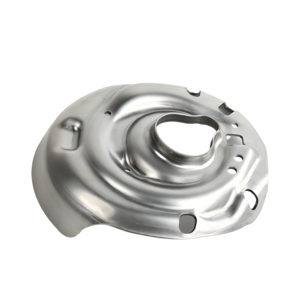
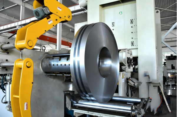
The route runs from coil feeding through progressive stamping, forming, piercing, trimming, calibration, washing, and inspection, on a 250-ton mechanical press with a one-cavity progressive die built in our in-house stamping die shop.
At launch, the line ran at 18 strokes per minute with a first-pass yield of 93.1%. The main rejects came from springback, hole-position deviation, forming cracks, and burrs. Over four weeks, the team made three changes:
- Added a pre-forming step before piercing.
- Added a calibration station to control mounting-surface flatness, hole position, overall height, and forming angle.
- Optimized the strip layout.
|
Metric |
Before |
After |
|
Press speed |
18 SPM |
22 SPM |
|
Cycle time |
3.33 s/pc |
2.73 s/pc |
|
Material utilization |
68.9% |
72.5% |
|
First-pass yield |
93.1% |
98.2% |
|
Springback-related reject rate |
2.8% |
0.7% |
|
Hole-position reject rate |
2.0% |
0.5% |
|
Forming-crack reject rate |
1.5% |
0.4% |
|
Burr and other reject rate |
0.6% |
0.2% |
For buyers, the practical result is capacity and cost. The same press and die now produce about 22% more parts per hour with less scrap, and the total reject rate fell from 6.9% to 1.8%, a reduction of roughly three quarters.
Quality Control and Automation Keep Shock Absorber Production Consistent
Consistency comes from inspection gates at each stage and from records that let the customer see them.
Inspection Gates from Incoming Material to Finished Product
Typical records include material certificates, dimensional reports, weld inspection results, pull-off data, coating and salt-spray reports, and airtightness test data.
Destructive and Non-Destructive Testing
Macro-sections and pull-off tests verify weld strength on samples, while ultrasonic, magnetic particle, and penetrant methods check welds without destroying the part.
Statistical Process Control, PFMEA, and Corrective Actions
SPC charts track critical dimensions in real time, PFMEA identifies risks before launch, and MSA confirms that gauges are capable. When a characteristic drifts, the reaction plan triggers containment, root-cause analysis, and corrective action.
Packaging, Identification, and PPAP
Parts are identified and packaged to prevent transit damage and to keep traceability to the production batch. The PPAP package, including process flow, PFMEA, control plan, MSA, capability data, and inspection results, gives the customer the evidence needed for approval.
RFQ Checklist for Shock Absorber Components
Include the following in your RFQ to get an accurate quote in the first round:
- 2D drawing and 3D model, with revision level
- Material grade and thickness, or tube size and wall thickness
- Annual volume and expected ramp-up
- Coating specification and salt-spray requirement
- Welding requirements, including leak-test pressure and leak-rate limit
- Test methods and acceptance criteria, such as pull-off force and critical dimensions
- Packaging and labeling requirements
- Traceability method
- Required PPAP level
- Inspection records required with each shipment
Upload your drawings and specifications through our contact page to request a quotation. Shaoyi's engineering team provides a technical analysis within 12 hours.
Conclusion
The shock absorber manufacturing process links material traceability, stamping, tube preparation, machining, welding, surface treatment, and inspection. For the metal-component supplier, every step has to match the drawing, the control plan, and the records the customer needs for approval.
The best way to evaluate a supplier of custom automotive stamping parts and welded assemblies is to look at the evidence: how they control forming defects, how they verify welds and coatings, and what their data looks like before and after an improvement.
FAQ
What materials and thicknesses are common for spring seats?
Spring seats commonly use formable low-carbon or high-strength steel sheet. In Shaoyi production, the typical thickness is 2.00mm-3.00mm. The final grade and thickness depend on load, geometry, and forming severity, so the RFQ should state material certification, tensile properties, and thickness tolerance.
How is airtightness tested after outer-tube welding?
Welded chambers are tested with air-pressure-decay or helium leak methods. The specification defines test pressure, stabilization and hold time, leak-rate limit, equipment calibration, and sampling plan. Weld penetration, joint strength, and position are verified separately.
When should a mounting eye use cold heading?
Cold heading suits high-volume mounting eyes with compact, symmetric geometry and a suitable wire grade, where near-net forming saves material and machining time. Forging or machining is the better choice for complex geometry, larger sections, lower volumes, or substantial material removal.
How should piston-rod plating be specified?
State the route: cold-drawn bar, induction hardening, grinding, chromium plating, and polishing. The drawing or coating specification should give diameter, straightness, roundness, roughness, plating thickness, adhesion, corrosion resistance, masking areas, and permitted defects such as pits, peeling, scratches, or exposed substrate.
What PPAP documents should a supplier provide?
A typical package includes the process flow, PFMEA, control plan, MSA, capability data, material certificates, dimensional reports, weld and coating reports, test results, packaging details, and traceability method, at the PPAP level the customer requests.
Who performs valve, oil, gas, and damping-force calibration?
The shock absorber manufacturer performs valve-stack assembly, oil filling, gas charging, and damping-force calibration. The metal supplier provides controlled tubes, brackets, seats, covers, mounting eyes, and rods, with the required inspection records.
Which quality records should a supplier retain?
Incoming material records, process parameters, dimensional inspection, weld inspection, coating and salt-spray reports, pull-off results, airtightness data, nonconformance records, corrective actions, and shipment traceability, kept for the retention period the customer requires.