Pienet erät, korkeat standardit. Nopea prototyypinkehityspalvelumme tekee vahvistamisen nopeammaksi ja helpommaksi —

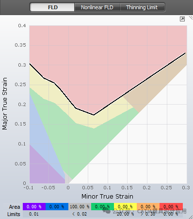
FLD-kaavion 7 avainvyöhykettä AutoForm -ohjelmistossa
Autoteollisuudessa tietokoneavusteisella insinöörityökalulla (CAE) on keskeinen rooli tuotekehitysprosessissa. Yksi edistyneimmistä CAE-työkaluista levyjen muovauksen simulointiin on AutoForm, joka auttaa insinöörejä ennustamaan ja estämään virheitä, kuten murtumista, ryplettymistä ja liiallista ohentumista elementtimenetelmän (FEA) avulla.
AutoFormin ydinominaisuus on muotoutumisrajakäyrä (FLD), tehokas työkalu levyn muotoutumisrajojen arviointiin. FLD jakaa materiaalin venymätilat seitsemään värilliseen vyöhykkeeseen, mikä mahdollistaa insinöörien visuaalisen arvioinnin osan hajoamisriskistä muotoutumisen aikana.
Tutkitaanpa seitsemää FLD-vyöhykettä ja niiden merkitystä:
1. Murtumisvyöhyke (Punainen)
Tämä vyöhyke sijaitsee muovausrajan käyrän (FLC) yläpuolella ja ilmaisee, että materiaali on ylittänyt muovausrajan ja siinä on suuri todennäköisyys murtumiseen. Minkä tahansa pisteen osalta, joka sijoittuu tähän punaiseen vyöhykkeeseen, on tehtävä välitön korjaus työkaluihin, materiaaliin tai prosessiin.
2. Murtumariskivyöhyke (Keltainen)
Tämä vyöhyke sijaitsee juuri murtumavyöhykkeen alapuolella ja kuvaa korkean riskin aluetta. Vaikka materiaali ei ole vielä murtunut, se toimii hyvin lähellä rajaaan. Ennaltaehkäisevät toimet ovat suositeltavia – joko muovausparametrien säätöä tai materiaalin ominaisuuksien muuttamista, jotta venymätaso pysyy poissa tästä vaaravyöhykkeestä.
3. Liiallisen ohentumisvyöhyke (Oranssi)
Liiallinen ohentuminen tarkoittaa, että levyn paksuus on vähentynyt hyväksyttävän rajan alapuolelle, mikä heikentää osan rakenteellista lujuutta ja kestävyyttä. Tämä johtuu usein liiallisesta venymisestä paikallisilla alueilla, eikä sitä tulisi sallia turvallisuudellisesti kriittisissä komponenteissa.
4. Turvavyöhyke (Vihreä)
Tämä on ideaali muovauskonditio. Tähän vyöhykkeeseen kuuluvat osat ovat optimaalisella muodonmuutostasolla, mikä tarkoittaa, että ne eivät todennäköisesti murtu, rypleydy tai ohene liikaa. Tämä on kaikkien kriittisten tuotealueiden tavoitevyöhyke.
5. Riittämätön venymävyöhyke (Harmaa)
Kun levyt metalli ei veny tarpeeksi, se ei välttämättä muodostu täsmälleen haluttuun muotoon. AutoForm merkitsee nämä alueet harmaalla värillä. Vaikka nämä alueet voivat joskus olla hyväksyttäviä ei-toiminnallisissa kohdissa, kuten reuno- tai leikkausalueilla, niiden määrää tulisi minimoitaa tuotepintojen säilyttämiseksi mittojen tarkkuuden vuoksi.
6. Ryplivyöhyke (Sininen)
Tämä vyöhyke viittaa mahdolliseen ryplemiseen. Vaikka kyseessä ei vielä ole murtuminen, rypleitä voi syntyä, jos tietyt olosuhteet jatkuvat. Tekninen arviointi, jota tukevat rypleiden korkeusmittaukset ja kokemus muovauksesta, on olennaista riskin hallinnassa.
7. Ryplesyysvyöhyke (Violetti)
Kun materiaali on päässyt ryppyvyöhykkeelle, näkyvä ryppyluova on jo syntynyt. Tämä heikentää sekä ulkonäköä että toiminnallisuutta. Koneistusvälitysinsinöörien on tällöin tarkistettava muottisuihkeita tai muutettava vetonaulojen asettelua ryppyjen välttämiseksi tai hallitsemiseksi.
Miksi FLD on tärkeä autoteollisuuden CAE-analyysissa?
AutoFormin FLD-kaavioiden avulla insinöörit voivat simuloida ja ennustaa muovausongelmia jo varhain suunnitteluvaiheessa. Tämä auttaa:
·Poistamaan kokeiluun perustuvan kehitystyön työkalujen valmistuksessa
·Vähentämään aikaa ja tuotantokustannuksia
·Parantamaan laatua ja toistettavuutta sarjatuotannossa
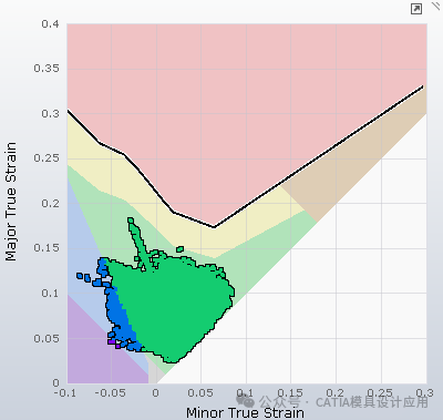
Käytännön sovellusanalyysi
Alla on esimerkki FLD-kaaviosta todellisesta komponenttisimuloinnista. Näetkö, onko tämä osa murtumis- tai ryppyriskissä? Onko suurin osa venymäpisteistä vihreällä alueella, vai onko olemassa huolestuttavia kohtia?
Jaa kommentteihin analyysisi – haluaisimme kuulla tulkintasi!