 Small batches, high standards. Our rapid prototyping service makes validation faster and easier —
 EN


Automotive Stamping Die CAE & FEA Design Guide: From Simulation to Mass Production Precision
Master modern automotive stamping die design utilizing CAE and FEA simulation. Explore drawbead modeling, springback compensation for advanced high-strength steels, chassis part forming, and IATF 16949-compliant quality verification loops.
Precision automotive stamping die design has evolved from an empirical workshop craft into an exact computational science. In high-volume automotive manufacturing programs, relying on manual die grinding and repeated physical tryouts to resolve springback, wrinkling, or splitting is no longer commercially viable. Modern Tier-1 programs demand that forming risks are systematically eliminated in the virtual environment before tool steel is ever cut.
The role of Computer-Aided Engineering (CAE) and Finite Element Analysis (FEA) has fundamentally transitioned: from an afterthought validation check to the generative core of the stamping process plan. Advanced sheet metal forming simulation now establishes the optimal drawbead configuration, blank holder force trajectory, and inverse die face compensation required to guarantee that T0 prototype panels land strictly within critical ±0.25 mm tolerance envelopes.
Key Definitions: Mastering the Language of Stamping Die CAE Design
Seamless communication between Tier-1 program managers, toolroom engineers, and CAE specialists relies on standard engineering definitions. In advanced cae die design for automotive parts, four core concepts form the analytical foundation:
- Finite Element Analysis (FEA) in Metal Forming: Discretizing the sheet metal blank into shell or solid elements to solve non-linear plasticity, contact mechanics, and stress-strain evolution under press kinematics. It produces quantitative engineering outputs: Forming Limit Diagrams (FLD), thinning gradient maps, and principal stress vectors.
- Drawbeads (Physical vs. Equivalent): Geometric ridges and matching grooves machined into the binder surface that bend and unbend the metal to regulate material inflow into the die cavity. Equivalent drawbeads apply mathematical resistance factors for rapid layout screening, whereas physical 3D drawbeads model actual tool geometry for final CNC machining.
- Springback: The geometric distortion caused by elastic strain recovery upon die unloading. In Advanced High-Strength Steels (AHSS), severe springback generates sidewall curl, angle opening, and torsional warp, demanding precision automotive stamping springback analysis and CAD surface compensation.
- Addendum Surfaces: Process transition surfaces engineered beyond the part boundary—including punch entry radii, binder wrap surfaces, and trim run-outs—designed to balance draw depth, avoid localized necking, and provide clean trimming datums for dedicated automotive stamping dies.
Key Stages of CAE Simulation in Automotive Stamping Die Design
Executing high-fidelity stamping die cae analysis follows a rigorous closed-loop engineering workflow:
1. Geometry Cleanup, Mid-Surface Extraction & Adaptive Meshing
Native product CAD models frequently contain microscopic surface gaps, tiny slivers, and mismatched normals that disrupt contact algorithms. CAE engineers clean up topology and generate adaptive meshes: establishing coarser elements across broad flat panels for computational speed, while automatically refining element density around tight fillet radii and drawbead profiles. Maintaining at least 4 to 6 elements across a fillet arc is vital to prevent severe underestimation of bending strain and springback.
2. Press Kinematics & Dynamic Boundary Conditions
Accurate simulation requires replicating physical press room realities. Rather than applying static blank holder tonnages, simulations incorporate dynamic force-vs-stroke curves matching hydraulic cushions or nitrogen gas spring manifolds. Furthermore, Coulomb friction coefficients are calibrated against specific plant lubrication regimes, PVD die surface coatings, and sheet mill surface roughness standards, as documented in technical forming studies from the American Iron and Steel Institute (AISI).
3. Explicit vs. Implicit Solver Synergy
Modern stamping simulation utilizes a dual-solver architecture. Dynamic explicit solvers efficiently process highly non-linear, large-deformation drawing and flanging sequences without numerical convergence stalling. Once the forming stroke is complete, the full stress-strain tensor is transferred to a static implicit solver to calculate unconstrained equilibrium states during springback with maximum mathematical precision.
Simulation of Drawing Processes and Addendum Surface Modeling
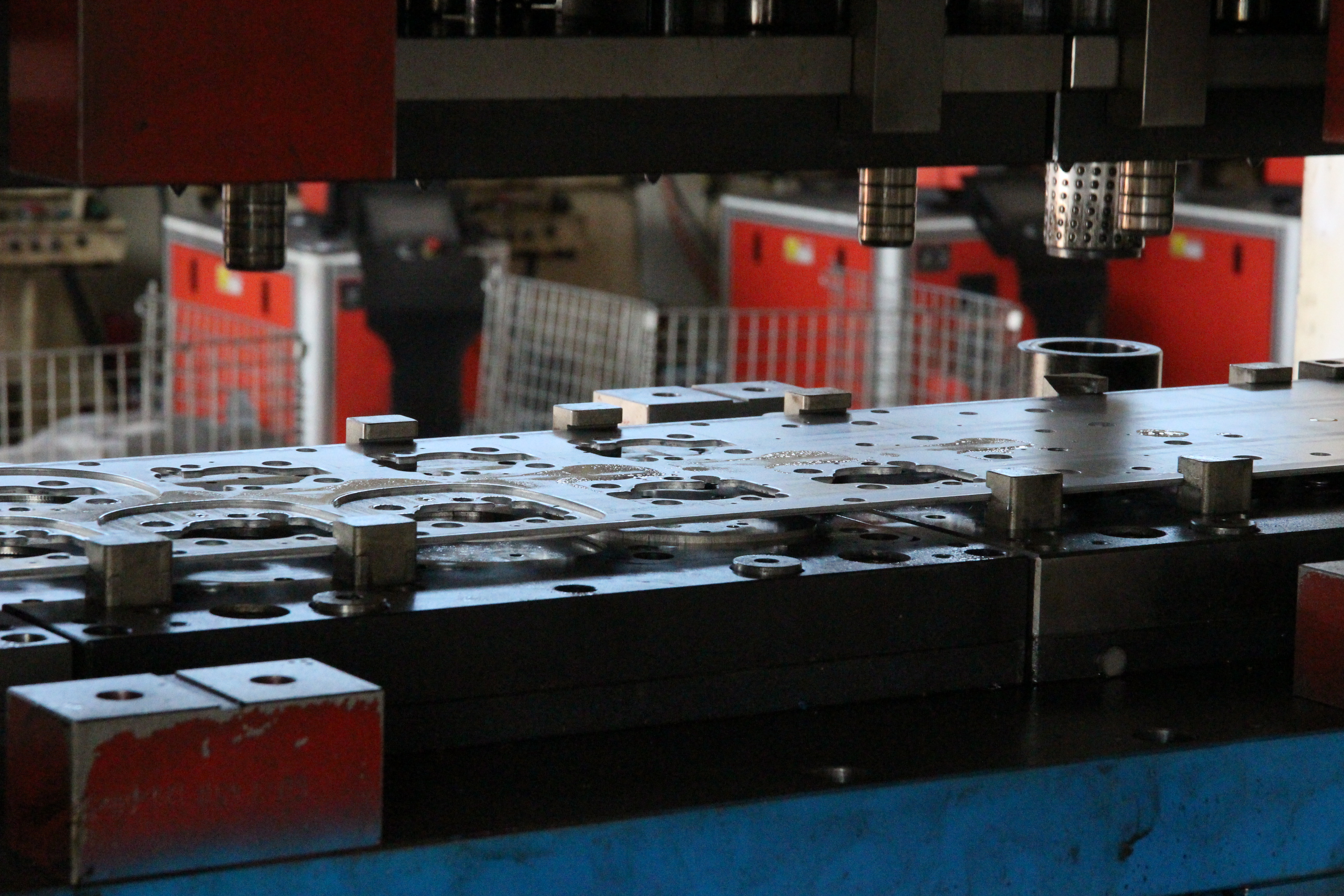
The deep drawing station accounts for the highest risk and capital investment across the stamping process chain. Once drawing surfaces are cut incorrectly, tool salvage requires extensive weld buildup or complete insert replacement. Applying sheet metal forming simulation at this juncture delivers the highest engineering ROI.
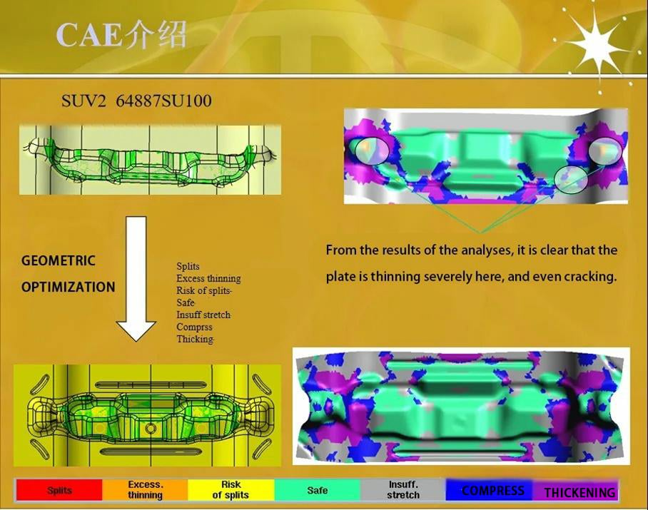
CAE engineers first identify localized flow differentials: material surpluses induce wrinkling, while material starvation causes localized necking or splitting. Drawbead resistance profiles are iteratively tuned—utilizing continuous beads along straight boundaries and segmented beads near corner fillets—to harmonize material draw-in velocity across complex geometries, adhering to core strip layout design principles for progressive dies.
DFM Engineering Insight: The Power of Virtual Wall Optimization
During the early DFM stage, presenting virtual FLD and thinning contour plots allows Tier-2 suppliers to guide OEM design teams constructively. Increasing a restrictive product corner radius by merely 1.5 mm or adding a 2° draft angle often completely eliminates an expensive restrike operation and avoids ongoing edge cracking risks during mass production.
Springback Analysis and Compensation in High-Strength Steel Stamping
Advanced High-Strength Steels (AHSS, including DP600, DP780, and CP980) shift the primary manufacturing hurdle from "can it form without tearing" to "will it meet GD&T specs after springback." Higher yield strengths dramatically increase elastic strain energy, causing profound dimensional distortion upon press unloading.
Standard isotropic hardening constitutive models systematically underestimate springback because they ignore the Bauschinger effect during cyclic bending and unbending across drawbeads. Reliable automotive stamping springback analysis incorporates kinematic and mixed hardening material models parameterized with empirical cyclic loading curves, such as those provided in SSAB's Docol AHSS steel data.
Iterative Inverse Surface Compensation
Surface compensation utilizes the inverse displacement vector methodology. FEA software computes the springback displacement field at every node on the stamping, then displaces the CAD tooling face in the opposite direction. Because modifying the die face alters material contact and plastic strain distribution, compensation is executed over 2 to 3 converging simulation loops until the springback part matches nominal CAD specifications within ±0.25 mm.
Engineering Case: Resolving ±1.2 mm Springback on HC340/590DP Inner Reinforcement
On a safety-critical 1.8 mm HC340/590DP dual-phase automotive body reinforcement, initial T0 trial panels displayed ±1.2 mm springback flaring across the main mounting flange. Shaoyi's engineering team ran iterative FEA compensation models, calculated an inverse 1.8° overbend profile on the draw die, and incorporated calibrated restrike coining beads. Within six days, dimensional springback was stabilized to within ±0.25 mm across full-batch CPK verification runs.
Special Simulation Requirements for Chassis and Suspension Components
Unlike cosmetic outer body panels where Class-A surface finish is paramount, fea analysis of automotive stamping parts in the chassis domain focuses heavily on structural integrity, fatigue performance, and heavy gauge mechanics across custom automotive stamped parts:
- Thick-Plate Solid & Thick-Shell Modeling: Chassis components (such as control arms, subframe brackets, and spring perches) frequently utilize heavy sheet (2.5 mm to 4.5 mm). Thin-shell assumptions fail because through-thickness normal and shear stresses significantly influence forming forces and inner bend thinning.
- Forming Residual Stress to Fatigue CAE Transfer: High-tensile residual stresses locked into the outer fibers of stamped brackets can accelerate micro-crack propagation under alternating road vibrations. Shaoyi maps forming residual stress and plastic strain tensors directly into downstream durability FEA solvers to guarantee fatigue life compliance.
- Welded Assembly Pre-Deformation Compensation: Chassis stampings are typically joined into complex subassemblies. Thermal shrinkage from robotic MIG/MAG welding introduces secondary distortions. Accurately predicting individual stamping springback allows engineers to pre-offset mating tabs, ensuring final welded assemblies locate perfectly onto vehicle mounting fixtures.
Comparison of Mainstream CAE Stamping Simulation Platforms
While software suites provide advanced solvers, true simulation accuracy depends on material card fidelity, press room calibration, and engineering interpretation experience.
| Simulation Platform | Primary Application Focus | Key Engineering Strengths | Typical Tooling Phase |
|---|---|---|---|
| AutoForm | Process planning & rapid springback compensation | Highly automated binder/drawbead generation, fast solver turnaround, intuitive compensation loops | Early DFM feasibility, concept quoting & rapid surface iteration |
| Dynaform / LS-DYNA | Complex general forming & heavy-plate mechanics | Robust explicit solver handles extreme deformations, thick-plate shearing, and complex kinematic tools | Detailed multi-station validation & heavy chassis stampings |
| PAM-STAMP | Full process chain & hot stamping simulation | Seamless chaining from drawing to trimming, restrike, and press-hardened boron steel thermal quenching | Multi-stage safety assemblies & hot forming lines |
From Virtual Simulation to Mass Production: The IATF 16949 Quality Loop
The hallmark of a tier-level stamping die supplier is not producing colorful CAE contour plots, but achieving tight correlation between virtual predictions and physical T0 parts. Under an accredited IATF 16949:2016 framework, simulation is deeply integrated across development:
- Empirical Correlation as an Asset: Every T0/T1 physical trial is treated as a validation benchmark. High-density CMM point clouds and optical scan meshes are superimposed directly over CAE springback predictions. Discrepancies are used to fine-tune in-house friction calibration tables and press cushion response curves.
- APQP, DFMEA & Control Plan Integration: Potential failure modes identified in DFMEA (e.g., edge cracking during hole flanging) link directly to FLD monitoring points in simulation. Key characteristics (KPCs) in Control Plans correspond to springback compensation convergence zones, as detailed in our guide on the APQP and PPAP process and PPAP sample documentation.
- Tooling Wear & Burr Control: Advanced simulation guides the selection of wear-resistant punch materials (DC53, SKD11, Tungsten Carbide) and PVD coatings, establishing predetermined punch sharpening cycles to maintain burr heights below 0.08 mm — principles explored in our review of metal stamping burr removal techniques.
Procurement ROI: The Economics of Upfront CAE Investment
From a Tier-1 procurement perspective, tooling purchase price represents only a fraction of total program cost. The true budget drainers are repeated die modification cycles, delayed SOP launch penalties, and persistent serial scrap rates.
Tooling Development ROI Calculation Framework
Upfront Investment: Specialized CAE engineer hours + advanced material card testing.
Direct Program Savings: Eliminating 2 to 3 rounds of physical die welding and CNC re-machining saves ¥40,000–¥120,000 per die set, accelerates SOP milestones by 4 to 8 weeks, and secures consistent CPK ≥ 1.33 across 300,000+ stroke mass production lifecycles.
Furthermore, sourcing with a partner that integrates in-house CAE simulation, die manufacturing, and automated press stamping eliminates cross-supplier blame chains. Learn more about our manufacturing background on the Shaoyi company profile.
Key Takeaways for Automotive Engineering & Sourcing Teams
- CAE is the First Line of Defense: Resolving thinning, wrinkling, and splits in simulation costs hours of engineering time, whereas fixing defects after tool machining costs weeks of delay and substantial retooling capital.
- AHSS Demands Advanced Springback Compensation: High-strength stamping requires kinematic hardening material models, multi-operation stress mapping, and iterative inverse die face compensation.
- Chassis Parts Require Thick-Plate & Fatigue Mapping: Safety components necessitate thick-shell or solid element meshing and direct residual stress handoffs into downstream fatigue CAE solvers.
- Integrated Capabilities Eliminate Hand-Off Risks: Suppliers possessing seamless in-house simulation, toolmaking, and serial stamping capabilities ensure rapid problem resolution and guaranteed dimensional accountability.
Frequently Asked Questions (FAQ)
What is the primary difference between explicit and implicit solvers in stamping CAE?
Dynamic explicit solvers excel at solving highly non-linear, large-deformation drawing and flanging operations with stable computation times. Conversely, static implicit solvers provide superior mathematical precision when calculating equilibrium states during unconstrained springback and die unloading.
Why is equivalent drawbead modeling insufficient for final progressive die design?
Equivalent drawbeads apply a uniform mathematical resistance coefficient, which is ideal for rapid early-stage layout screening. However, they average out localized shear deformation, corner radius wear, and material thinning, making physical 3D drawbead geometry essential for detailed tool surface machining.
How does Shaoyi close the quality loop between simulation models and T0 physical trials?
Every T0/T1 trial acts as a calibration experiment: actual 3D CMM point clouds and optical scans are superimposed over FEA springback prediction vectors. The verified deviations are back-fed into material cards (using actual heat-lot tensile data) and in-house press friction models under our IATF 16949 APQP framework.
What CAD and CAE data packages are required for an initial 24-hour DFM quote?
Tier-1 suppliers can submit 3D CAD models (STEP/IGES/Parasolid), 2D GD&T drawings with critical datum points, specified material grades (e.g., DP600, HSLA 420), and planned annual production volumes for a comprehensive feasibility and cost analysis within 24 hours.